
User Manual
Page 3
... 5 1.1 Package Contents 5 1.2 Specifications 6 1.3 Supported AGP VGA Cards Lists for AGI Slot 9 1.4 Supported PCI Express VGA Cards Lists for AGI Express Slot (PCI Express x 4 11 1.5 Motherboard Layout 12 1.6 ASRock 8CH I/O 13 2 Installation 14 2.1 Screw Holes 14 2.2 Pre-installation Precautions 14 2.3 CPU Installation 15 2.4 Installation of Heatsink and CPU fan 17 2.5 Installation of Memory...
... 5 1.1 Package Contents 5 1.2 Specifications 6 1.3 Supported AGP VGA Cards Lists for AGI Slot 9 1.4 Supported PCI Express VGA Cards Lists for AGI Express Slot (PCI Express x 4 11 1.5 Motherboard Layout 12 1.6 ASRock 8CH I/O 13 2 Installation 14 2.1 Screw Holes 14 2.2 Pre-installation Precautions 14 2.3 CPU Installation 15 2.4 Installation of Heatsink and CPU fan 17 2.5 Installation of Memory...

User Manual
Page 5
... information of the Support CD. Chapter 3 and 4 contain the configuration guide to quality and endurance. ASRock website http://www.asrock.com 1.1 Package Contents ASRock 775Dual-915GV Motherboard (Micro ATX Form Factor: 9.6-in x 9.6-in, 24.4 cm x 24.4 cm) ASRock 775Dual-915GV Quick Installation Guide ASRock 775Dual-915GV Support CD (including LGA 775 CPU Installation Live Demo) One 80-conductor Ultra ATA 66/100...
... information of the Support CD. Chapter 3 and 4 contain the configuration guide to quality and endurance. ASRock website http://www.asrock.com 1.1 Package Contents ASRock 775Dual-915GV Motherboard (Micro ATX Form Factor: 9.6-in x 9.6-in, 24.4 cm x 24.4 cm) ASRock 775Dual-915GV Quick Installation Guide ASRock 775Dual-915GV Support CD (including LGA 775 CPU Installation Live Demo) One 80-conductor Ultra ATA 66/100...

User Manual
Page 8
.... 2. Power Management for AGI Express Slot (PCI Express x 4)" on page 20. 8. Although this motherboard supports 2-channel, 4-channel, 6-channel, and 8-channel modes. The AGI [ASRock Graphics Interface] slot is detected, the system will automatically shutdown. For audio output, this motherboard offers stepless control, it back again. shared memory capacity. 9. For the information of PCI...
.... 2. Power Management for AGI Express Slot (PCI Express x 4)" on page 20. 8. Although this motherboard supports 2-channel, 4-channel, 6-channel, and 8-channel modes. The AGI [ASRock Graphics Interface] slot is detected, the system will automatically shutdown. For audio output, this motherboard offers stepless control, it back again. shared memory capacity. 9. For the information of PCI...

User Manual
Page 12
... 2 x 184-pin DDR DIMM Slots (Dual Channel B: DDR1, DDR2; 1.5 Motherboard Layout 12 3 4 24.4cm (9.6 in) PS2 Mouse 1 PS2_USB_PWR1 ATX12V1 CPU_FAN1 ...USB 2.0 T: USB2 B: USB3 USB 2.0 T: USB0 B: USB1 Top: RJ-45 CD1 ATXPWR1 ` Intel 915GV Chipset AGI_EXPRESS1 PCI EXPRESS 775Dual-915GV Dual Channel IDE1 SATA SATA4 SATA3 CMOS Battery AGI LAN PHY CLRCMOS1 1 PCI 1 AUDIO CODEC AUDIO1 1 ...Header (SPEAKER 1) 19 System Panel Header (PANEL1) 20 South Bridge Controller 21 North Bridge Controller 22 ASRock Graphics Interface Slot (AGI) 23 COM Port Header (COM1) 24 AMR Slot (AMR1) 25 JR1 /...
... 2 x 184-pin DDR DIMM Slots (Dual Channel B: DDR1, DDR2; 1.5 Motherboard Layout 12 3 4 24.4cm (9.6 in) PS2 Mouse 1 PS2_USB_PWR1 ATX12V1 CPU_FAN1 ...USB 2.0 T: USB2 B: USB3 USB 2.0 T: USB0 B: USB1 Top: RJ-45 CD1 ATXPWR1 ` Intel 915GV Chipset AGI_EXPRESS1 PCI EXPRESS 775Dual-915GV Dual Channel IDE1 SATA SATA4 SATA3 CMOS Battery AGI LAN PHY CLRCMOS1 1 PCI 1 AUDIO CODEC AUDIO1 1 ...Header (SPEAKER 1) 19 System Panel Header (PANEL1) 20 South Bridge Controller 21 North Bridge Controller 22 ASRock Graphics Interface Slot (AGI) 23 COM Port Header (COM1) 24 AMR Slot (AMR1) 25 JR1 /...

User Manual
Page 14
... component, ensure that the power is switched off or the power cord is a Micro ATX form factor (9.6" x 9.6", 24.4 x 24.4 cm) motherboard. Doing so may cause severe damage to you handle components. 3. Also remember to use a grounded wrist strap or touch a safety grounded object before...remove any component. 2. Hold components by circles to secure the motherboard to ensure that comes with the component. Unplug the power cord from the power supply. Do not over-tighten the screws! Chapter 2 Installation 775Dual-915GV is detached from the wall socket before installing or removing the...
... component, ensure that the power is switched off or the power cord is a Micro ATX form factor (9.6" x 9.6", 24.4 x 24.4 cm) motherboard. Doing so may cause severe damage to you handle components. 3. Also remember to use a grounded wrist strap or touch a safety grounded object before...remove any component. 2. Hold components by circles to secure the motherboard to ensure that comes with the component. Unplug the power cord from the power supply. Do not over-tighten the screws! Chapter 2 Installation 775Dual-915GV is detached from the wall socket before installing or removing the...

User Manual
Page 16
Step 4-2. This cap must be placed if returning the motherboard for after service. Close the socket: Step 4-1. Secure load lever with right hand thumb and peel the cap from the socket while pressing on load ...
Step 4-2. This cap must be placed if returning the motherboard for after service. Close the socket: Step 4-1. Secure load lever with right hand thumb and peel the cap from the socket while pressing on load ...
User Manual
Page 17
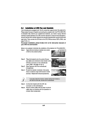
...LAND CPU to dissipate heat. Before you installed the heatsink, you press down on fastener caps with the CPU fan connector on the motherboard. Place the heatsink onto the socket. Rotate the fastener clockwise, then press down the fasteners without rotating them clockwise, the heatsink ...cannot be secured on the motherboard. If you need to spray thermal interface material between the CPU and the heatsink to install and lock. Connect fan header with ...
...LAND CPU to dissipate heat. Before you installed the heatsink, you press down on fastener caps with the CPU fan connector on the motherboard. Place the heatsink onto the socket. Rotate the fastener clockwise, then press down the fasteners without rotating them clockwise, the heatsink ...cannot be secured on the motherboard. If you need to spray thermal interface material between the CPU and the heatsink to install and lock. Connect fan header with ...

User Manual
Page 18
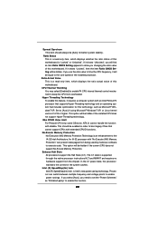
... 1. It is not allowed to install both DDR and DDRII to install identical DDRII DIMM pair in Dual Channel B (DDR1 and DDR2; otherwise, this motherboard and DIMM may be activated. 2.5 Installation of the same color. see p.12 No.6), so that Dual Channel Memory Technology can be damaged. 3. It ... may refer to install identical (the same brand, speed, size and chip-type) DDR DIMM pair in the slots of Memory Modules (DIMM) 775Dual-915GV motherboard provides two 184-pin DDR (Double Data Rate) DIMM slots and two 240-pin DDRII DIMM slots, and supports Dual Channel Memory Technology. Yellow...
... 1. It is not allowed to install both DDR and DDRII to install identical DDRII DIMM pair in Dual Channel B (DDR1 and DDR2; otherwise, this motherboard and DIMM may be activated. 2.5 Installation of the same color. see p.12 No.6), so that Dual Channel Memory Technology can be damaged. 3. It ... may refer to install identical (the same brand, speed, size and chip-type) DDR DIMM pair in the slots of Memory Modules (DIMM) 775Dual-915GV motherboard provides two 184-pin DDR (Double Data Rate) DIMM slots and two 240-pin DDRII DIMM slots, and supports Dual Channel Memory Technology. Yellow...

User Manual
Page 19
... adding or removing DIMMs or the system components. Unlock a DIMM slot by pressing the retaining clips outward. Step 3. Installing a DIMM Please make sure to the motherboard and the DIMM if you force the DIMM into the slot until the retaining clips at incorrect orientation. Align a DIMM on the slot such that...
... adding or removing DIMMs or the system components. Unlock a DIMM slot by pressing the retaining clips outward. Step 3. Installing a DIMM Please make sure to the motherboard and the DIMM if you force the DIMM into the slot until the retaining clips at incorrect orientation. Align a DIMM on the slot such that...

User Manual
Page 20
...is completely seated on AGP VGA card or PCI Express VGA card, BIOS setup will be the primary VGA card. If you want this motherboard. Please read the documentation of the compatible PCI Express VGA cards, please refer to the "Supported PCI Express VGA Card List for later ...onboard VGA in Windows will automatically disable the onboard VGA. 2. AGI Express slot (PCI Express x 4): AGI Express slot (PCI Express x 4) is used to insert an ASRock MR card (optional) with screws. 20 PCI slots: PCI slots are 2 PCI slots, 1 AMR slot, 1 AGI slot, and 1 AGI Express slot (PCI Express...
...is completely seated on AGP VGA card or PCI Express VGA card, BIOS setup will be the primary VGA card. If you want this motherboard. Please read the documentation of the compatible PCI Express VGA cards, please refer to the "Supported PCI Express VGA Card List for later ...onboard VGA in Windows will automatically disable the onboard VGA. 2. AGI Express slot (PCI Express x 4): AGI Express slot (PCI Express x 4) is used to insert an ASRock MR card (optional) with screws. 20 PCI slots: PCI slots are 2 PCI slots, 1 AMR slot, 1 AGI slot, and 1 AGI Express slot (PCI Express...

User Manual
Page 21
... BIOS onboard VGA selection into "Enabled", and start your computer with onboard VGA if you want this motherboard supports Surround Display upgrade. 2.7 Surround Display Feature Thanks to ASRock patented AGI8X and AGI Express Technology, this motherboard to support multi-monitors. Clear CMOS (CLRCMOS1, 2-pin jumper) (see p.12 No. 28) 2-pin jumper Note: CLRCMOS1...
... BIOS onboard VGA selection into "Enabled", and start your computer with onboard VGA if you want this motherboard supports Surround Display upgrade. 2.7 Surround Display Feature Thanks to ASRock patented AGI8X and AGI Express Technology, this motherboard to support multi-monitors. Clear CMOS (CLRCMOS1, 2-pin jumper) (see p.12 No. 28) 2-pin jumper Note: CLRCMOS1...

User Manual
Page 22
... (39-pin IDE1, see p.12 No. 10) Pin1 FLOPPY1 the red-striped side to the SATA hard disk or the SATA connector on the motherboard. 22 2.9 Onboard Headers and Connectors Onboard headers and connectors are NOT jumpers. Do NOT place jumper caps over the headers and connectors will cause permanent...internal storage devices. FDD connector (33-pin FLOPPY1) (see p.12 No. 9) PIN1 IDE1 connect the blue end connect the black end to the motherboard to the IDE devices 80-conductor ATA 66/100 cable Note: Please refer to 1.5 Gb/s data transfer rate. The current SATA interface allows up to...
... (39-pin IDE1, see p.12 No. 10) Pin1 FLOPPY1 the red-striped side to the SATA hard disk or the SATA connector on the motherboard. 22 2.9 Onboard Headers and Connectors Onboard headers and connectors are NOT jumpers. Do NOT place jumper caps over the headers and connectors will cause permanent...internal storage devices. FDD connector (33-pin FLOPPY1) (see p.12 No. 9) PIN1 IDE1 connect the blue end connect the black end to the motherboard to the IDE devices 80-conductor ATA 66/100 cable Note: Please refer to 1.5 Gb/s data transfer rate. The current SATA interface allows up to...

User Manual
Page 25
... hard disks into the drive bays of the SATA data cable to install the SATA hard disks. 2.10 Serial ATA (SATA) Hard Disks Installation This motherboard adopts Intel ICH6 south bridge chipset that supports Serial ATA (SATA) hard disks. STEP 2: Connect the SATA power cable to the SATA hard disk. 25... end of the SATA data cable to the SATA hard disk. STEP 3: Connect one end of your chassis. This section will guide you to the motherboard's SATA connector.
... hard disks into the drive bays of the SATA data cable to install the SATA hard disks. 2.10 Serial ATA (SATA) Hard Disks Installation This motherboard adopts Intel ICH6 south bridge chipset that supports Serial ATA (SATA) hard disks. STEP 2: Connect the SATA power cable to the SATA hard disk. 25... end of the SATA data cable to the SATA hard disk. STEP 3: Connect one end of your chassis. This section will guide you to the motherboard's SATA connector.

User Manual
Page 26
... with the following BIOS setup screens and descriptions are for reference purpose only, and they may also restart by pressing the reset button on the motherboard stores the BIOS SETUP UTILITY. Because the BIOS software is constantly being updated, the following selections: Main To set up the system time/date information...
... with the following BIOS setup screens and descriptions are for reference purpose only, and they may also restart by pressing the reset button on the motherboard stores the BIOS SETUP UTILITY. Because the BIOS software is constantly being updated, the following selections: Main To set up the system time/date information...

User Manual
Page 28
... Configuration SuperIO Configuration USB Configuration Configure CPU Select Screen Select Item Enter Go to malfunction. Boot Failure Guard Enable or disable the feature of this motherboard. 3.3 Advanced Screen In this section, you may set the CPU host frequency. +F1 F9 F10 ESC Select Screen Select Item Change Option General Help Load...
... Configuration SuperIO Configuration USB Configuration Configure CPU Select Screen Select Item Enter Go to malfunction. Boot Failure Guard Enable or disable the feature of this motherboard. 3.3 Advanced Screen In this section, you may set the CPU host frequency. +F1 F9 F10 ESC Select Screen Select Item Change Option General Help Load...
User Manual
Page 29
...actual value of the installed processor. Ratio Actual Value This is a read -only item, which displays whether the ratio status of this motherboard. NT4.0) cannot handle the function with "No Execute (NX) Memory Protection" can switch between multiple frequency and voltage points to [Auto.... Set to enable power savings. This should always be [Auto] for this technology, such as "Portable/Laptop" to enable this motherboard is supported through the native processor instructions HLT and MWAIT and requires no hardware support from overheated. An IA-32 processor with disable....
...actual value of the installed processor. Ratio Actual Value This is a read -only item, which displays whether the ratio status of this motherboard. NT4.0) cannot handle the function with "No Execute (NX) Memory Protection" can switch between multiple frequency and voltage points to [Auto.... Set to enable power savings. This should always be [Auto] for this technology, such as "Portable/Laptop" to enable this motherboard is supported through the native processor instructions HLT and MWAIT and requires no hardware support from overheated. An IA-32 processor with disable....

User Manual
Page 30
... DDR DIMM: Configuration options are [5], [4], [3], and [Auto]. Configuration options: [2 DRAM Clocks], [3 DRAM Clocks], [4 DRAM Clocks], and [5 DRAM Clocks]. DRAM Frequency If [Auto] is selected, the motherboard will allow you adjusting them. It will detect the memory module(s) inserted and assigns appropriate frequency automatically. If you select [Disabled], you may also select...
... DDR DIMM: Configuration options are [5], [4], [3], and [Auto]. Configuration options: [2 DRAM Clocks], [3 DRAM Clocks], [4 DRAM Clocks], and [5 DRAM Clocks]. DRAM Frequency If [Auto] is selected, the motherboard will allow you adjusting them. It will detect the memory module(s) inserted and assigns appropriate frequency automatically. If you select [Disabled], you may also select...

User Manual
Page 31
No matter you may select [256MB] or [128MB] as the aperture size select. DVMT Mode Select Use this motherboard, you insert DDR or DDRII DIMM to this item to select DVMT Mode. The default value is [DVMT Mode]. OnBoard MC'97 Modem Select [Auto] ...or [Disabled] for the onboard AC'97 Audio feature. Configuration options: [High], [Low], and [Auto]. The default value of this motherboard, onboard VGA will always be automatically disabled when you install VGA cards to Precharge This controls the number of onboard VGA. OnBoard AC'97 Audio...
No matter you may select [256MB] or [128MB] as the aperture size select. DVMT Mode Select Use this motherboard, you insert DDR or DDRII DIMM to this item to select DVMT Mode. The default value is [DVMT Mode]. OnBoard MC'97 Modem Select [Auto] ...or [Disabled] for the onboard AC'97 Audio feature. Configuration options: [High], [Low], and [Auto]. The default value of this motherboard, onboard VGA will always be automatically disabled when you install VGA cards to Precharge This controls the number of onboard VGA. OnBoard AC'97 Audio...

User Manual
Page 38
... 1985-2005, American Megatrends, Inc. 38 Or you to monitor the status of the hardware on your system, including the parameters of the CPU temperature, motherboard temperature, CPU fan speed, chassis fan speed, and the critical voltage. Legacy USB Support Use this item to emulate the I/O devices of USB controller. USB...
... 1985-2005, American Megatrends, Inc. 38 Or you to monitor the status of the hardware on your system, including the parameters of the CPU temperature, motherboard temperature, CPU fan speed, chassis fan speed, and the critical voltage. Legacy USB Support Use this item to emulate the I/O devices of USB controller. USB...

User Manual
Page 42
...on a specific item then follow the installation wizard to visit ASRock's website at http://www.asrock.com; Since it . 4.2.4 "LGA 775 CPU Installation Live Demo" Program This motherboard is equipped with the motherboard contains necessary drivers and useful utilities that Intel has released. or... information. 42 We hope you may check this live demo program before you start the installation of CPU and motherboard damages caused by improper handling, ASRock sincerely presents you a clear installation guide through the following path: ..\ MPEGAV \ LGA775INST.DAT 4.2.5 Contact Information ...
...on a specific item then follow the installation wizard to visit ASRock's website at http://www.asrock.com; Since it . 4.2.4 "LGA 775 CPU Installation Live Demo" Program This motherboard is equipped with the motherboard contains necessary drivers and useful utilities that Intel has released. or... information. 42 We hope you may check this live demo program before you start the installation of CPU and motherboard damages caused by improper handling, ASRock sincerely presents you a clear installation guide through the following path: ..\ MPEGAV \ LGA775INST.DAT 4.2.5 Contact Information ...

