
User Manual
Page 3
...Supported AGP VGA Cards Lists for AGI Slot 8 1.4 Supported PCI Express VGA Cards Lists for AGI Express Slot (PCI Express x 4 10 1.5 Motherboard Layout 11 1.6 ASRock 8CH I/O 12 2 Installation 13 2.1 Screw Holes 13 2.2 Pre-installation Precautions 13 2.3 CPU Installation 14 2.4 Installation of Heatsink and CPU... Introduction 24 3.1.1 BIOS Menu Bar 24 3.1.2 Navigation Keys 25 3.2 Main Screen 25 3.3 Advanced Screen 25 3.3.1 CPU Configuration 26 3.3.2 Chipset Configuration 27 3.3.3 ACPI Configuration 29 3.3.4 IDE Configuration 30 3.3.5 PCIPnP Configuration 32 3.3.6 Floppy ...
...Supported AGP VGA Cards Lists for AGI Slot 8 1.4 Supported PCI Express VGA Cards Lists for AGI Express Slot (PCI Express x 4 10 1.5 Motherboard Layout 11 1.6 ASRock 8CH I/O 12 2 Installation 13 2.1 Screw Holes 13 2.2 Pre-installation Precautions 13 2.3 CPU Installation 14 2.4 Installation of Heatsink and CPU... Introduction 24 3.1.1 BIOS Menu Bar 24 3.1.2 Navigation Keys 25 3.2 Main Screen 25 3.3 Advanced Screen 25 3.3.1 CPU Configuration 26 3.3.2 Chipset Configuration 27 3.3.3 ACPI Configuration 29 3.3.4 IDE Configuration 30 3.3.5 PCIPnP Configuration 32 3.3.6 Floppy ...
User Manual
Page 4
4 Software Support 39 4.1 Install Operating System 39 4.2 Support CD Information 39 4.2.1 Running Support CD 39 4.2.2 Drivers Menu 39 4.2.3 Utilities Menu 39 4.2.4 "LGA 775 CPU Installation Live Demo" Program .. 39 4.2.5 Contact Information 39 4
4 Software Support 39 4.1 Install Operating System 39 4.2 Support CD Information 39 4.2.1 Running Support CD 39 4.2.2 Drivers Menu 39 4.2.3 Utilities Menu 39 4.2.4 "LGA 775 CPU Installation Live Demo" Program .. 39 4.2.5 Contact Information 39 4

User Manual
Page 5
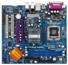
... Serial ATA (SATA) HDD Power Cable (Optional) One ASRock 8CH I/O One COM Port Bracket One ASRock MR Card (Optional) 5 ASRock website http://www.asrock.com 1.1 Package Contents ASRock 775Dual-915GL Motherboard (Micro ATX Form Factor: 9.6-in x 8.6-in, 24.4 cm x 21.8 cm) ASRock 775Dual-915GL Quick Installation Guide ASRock 775Dual-915GL Support CD (including LGA 775 CPU Installation Live Demo) One 80-conductor Ultra ATA 66...
... Serial ATA (SATA) HDD Power Cable (Optional) One ASRock 8CH I/O One COM Port Bracket One ASRock MR Card (Optional) 5 ASRock website http://www.asrock.com 1.1 Package Contents ASRock 775Dual-915GL Motherboard (Micro ATX Form Factor: 9.6-in x 8.6-in, 24.4 cm x 21.8 cm) ASRock 775Dual-915GL Quick Installation Guide ASRock 775Dual-915GL Support CD (including LGA 775 CPU Installation Live Demo) One 80-conductor Ultra ATA 66...

User Manual
Page 6
...: North Bridge: Intel® 915GL chipset, FSB @ 800 / 533MHz, supports Hyper-Threading Technology (see CAUTION 1) South Bridge: Intel® ICH6, supports SATA 1.5Gb/s Memory: 2 DDR DIMM slots: DDR1 and DDR2 supports PC3200 (DDR400) / PC2700 (...supports Wake-On-LAN Hardware Monitor:CPU temperature sensing, Chassis temperature sensing, CPU overheat shutdown to protect CPU life (ASRock U-COP)(see CAUTION 4), CPU fan tachometer, Chassis fan tachometer, Voltage monitoring: +12V, +5V, +3.3V, Vcore PCI slots: 2 PCI slots with PCI Specification 2.3 AMR slot: 1 slot, supports ASRock...
...: North Bridge: Intel® 915GL chipset, FSB @ 800 / 533MHz, supports Hyper-Threading Technology (see CAUTION 1) South Bridge: Intel® ICH6, supports SATA 1.5Gb/s Memory: 2 DDR DIMM slots: DDR1 and DDR2 supports PC3200 (DDR400) / PC2700 (...supports Wake-On-LAN Hardware Monitor:CPU temperature sensing, Chassis temperature sensing, CPU overheat shutdown to protect CPU life (ASRock U-COP)(see CAUTION 4), CPU fan tachometer, Chassis fan tachometer, Voltage monitoring: +12V, +5V, +3.3V, Vcore PCI slots: 2 PCI slots with PCI Specification 2.3 AMR slot: 1 slot, supports ASRock...

User Manual
Page 7
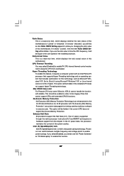
... information of the system or damage the CPU. 7 Please check the table on the motherboard functions properly and unplug the power cord, then plug it is a special design that only supports compatible AGP VGA cards. The AGI [ASRock Graphics Interface] slot is not recommended to... perform over-clocking. For audio output, this motherboard supports both stereo and mono modes. Frequencies other than the recommended CPU bus frequencies may cause the instability...
... information of the system or damage the CPU. 7 Please check the table on the motherboard functions properly and unplug the power cord, then plug it is a special design that only supports compatible AGP VGA cards. The AGI [ASRock Graphics Interface] slot is not recommended to... perform over-clocking. For audio output, this motherboard supports both stereo and mono modes. Frequencies other than the recommended CPU bus frequencies may cause the instability...
User Manual
Page 15
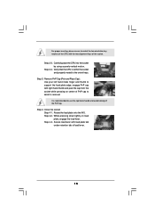
... cap. While pressing down lightly on center of PnP cap to assist in removal. Verify that the CPU is recommended to use the cap tab to the orient keys. Step 4. Secure load lever with the.... Step 3. Step 4-3. For proper inserting, please ensure to match the two orientation key notches of the CPU with load plate tab under retention tab of load lever. 15 Rotate the load plate onto the IHS. Step...Step 2-4. Remove PnP Cap (Pick and Place Cap): Use your left hand index finger and thumb to support the load plate edge, engage PnP cap with right hand thumb and peel the cap from the socket...
... cap. While pressing down lightly on center of PnP cap to assist in removal. Verify that the CPU is recommended to use the cap tab to the orient keys. Step 4. Secure load lever with the.... Step 3. Step 4-3. For proper inserting, please ensure to match the two orientation key notches of the CPU with load plate tab under retention tab of load lever. 15 Rotate the load plate onto the IHS. Step...Step 2-4. Remove PnP Cap (Pick and Place Cap): Use your left hand index finger and thumb to support the load plate edge, engage PnP cap with right hand thumb and peel the cap from the socket...
User Manual
Page 16
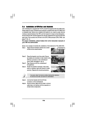
...Step 6. Step 2. Place the heatsink onto the socket. Secure excess cable with thumb to dissipate heat. Ensure that supports Intel 775-LAND CPU. Align fasteners with the CPU fan connector on the motherboard. Step 3. Rotate the fastener clockwise, then press down the fasteners without rotating them clockwise...be secured on the motherboard. Please adopt the type of heatsink and cooling fan compliant with 775-Pin socket that the CPU and the heatsink are oriented on the motherboard (CPU_FAN1, see page 11, No. 4). Connect fan header with the motherboard throughholes. ...
...Step 6. Step 2. Place the heatsink onto the socket. Secure excess cable with thumb to dissipate heat. Ensure that supports Intel 775-LAND CPU. Align fasteners with the CPU fan connector on the motherboard. Step 3. Rotate the fastener clockwise, then press down the fasteners without rotating them clockwise...be secured on the motherboard. Please adopt the type of heatsink and cooling fan compliant with 775-Pin socket that the CPU and the heatsink are oriented on the motherboard (CPU_FAN1, see page 11, No. 4). Connect fan header with the motherboard throughholes. ...
User Manual
Page 22
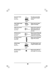
...power supply to this connector. 22 Please connect the chassis speaker to this header. GND +12V CPU_FAN_SPEED N/C Please connect a CPU fan cable to the ground pin. System Panel Header (9-pin PANEL1) (see p.11 No. 18) Chassis Speaker Header ...(4-pin SPEAKER 1) (see p.11 No. 13) Chassis Fan Connector (3-pin CHA_FAN1) (see p.11 No. 10) CPU Fan Connector (4-pin CPU_FAN1) (see p.11 No. 4) ATX Power Connector (20-pin ATXPWR1) (see p.11 No. 2) RRXD1 DDTR#1 DDSR#1 ...chassis fan cable to this connector and match the black wire to support a COM port module.
...power supply to this connector. 22 Please connect the chassis speaker to this header. GND +12V CPU_FAN_SPEED N/C Please connect a CPU fan cable to the ground pin. System Panel Header (9-pin PANEL1) (see p.11 No. 18) Chassis Speaker Header ...(4-pin SPEAKER 1) (see p.11 No. 13) Chassis Fan Connector (3-pin CHA_FAN1) (see p.11 No. 10) CPU Fan Connector (4-pin CPU_FAN1) (see p.11 No. 4) ATX Power Connector (20-pin ATXPWR1) (see p.11 No. 2) RRXD1 DDTR#1 DDSR#1 ...chassis fan cable to this connector and match the black wire to support a COM port module.
User Manual
Page 27
... will be enabled in order to allow you use the ratio value to time the CPU frequency, it shows "Locked", then the item Ratio CMOS Setting will be hidden if the installed CPU does not support Hyper-Threading technology. Intel (R) SpeedStep(tm) tech. Ratio Actual Value This is a...data pages from the chipset. This should be hidden if the current CPU does not support No-Excute Memory Protection. The C1 state is supported through the native processor instructions HLT and MWAIT and requires no hardware support from being used by malicious software to [Auto] if using Microsoft&#...
... will be enabled in order to allow you use the ratio value to time the CPU frequency, it shows "Locked", then the item Ratio CMOS Setting will be hidden if the installed CPU does not support Hyper-Threading technology. Intel (R) SpeedStep(tm) tech. Ratio Actual Value This is a...data pages from the chipset. This should be hidden if the current CPU does not support No-Excute Memory Protection. The C1 state is supported through the native processor instructions HLT and MWAIT and requires no hardware support from being used by malicious software to [Auto] if using Microsoft&#...
User Manual
Page 35
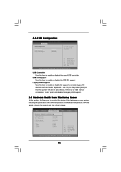
... you to enable or disable the use of the CPU temperature, motherboard temperature, CPU fan speed, chassis fan speed, and the critical voltage. Legacy USB Support Use this item to enable or disable the USB 2.0 support. USB 2.0 Support Use this item to enable or disable the support to auto-detect; etc. 3.3.8 USB Configuration BIOS SETUP UTILITY...
... you to enable or disable the use of the CPU temperature, motherboard temperature, CPU fan speed, chassis fan speed, and the critical voltage. Legacy USB Support Use this item to enable or disable the USB 2.0 support. USB 2.0 Support Use this item to enable or disable the support to auto-detect; etc. 3.3.8 USB Configuration BIOS SETUP UTILITY...

User Manual
Page 39
... Demo" Program This motherboard is a new CPU socket interface that enhance the motherboard features. 4.2.1 Running The Support CD To begin using the support CD, insert the CD into your CD-ROM drive. or you need to contact ASRock or want to know more about ASRock, welcome to your OS documentation for further ...information. 39 We hope you may find this live demo program before you start the installation of CPU and ...
... Demo" Program This motherboard is a new CPU socket interface that enhance the motherboard features. 4.2.1 Running The Support CD To begin using the support CD, insert the CD into your CD-ROM drive. or you need to contact ASRock or want to know more about ASRock, welcome to your OS documentation for further ...information. 39 We hope you may find this live demo program before you start the installation of CPU and ...


