
User Manual
Page 3
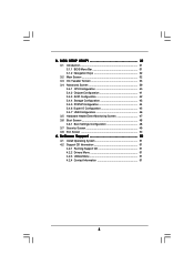
Installation 12 Pre-installation Precautions 12 2.1 CPU Installation 13 2.2 Installation of CPU Fan and Heatsink 13 2.3 Installation of Memory Modules (DIMM 14 2.4 Expansion Slots (PCI and PCI Express Slots 16 2.5 Jumpers Setup 17 2.6 Onboard Headers and Connectors ...
Installation 12 Pre-installation Precautions 12 2.1 CPU Installation 13 2.2 Installation of CPU Fan and Heatsink 13 2.3 Installation of Memory Modules (DIMM 14 2.4 Expansion Slots (PCI and PCI Express Slots 16 2.5 Jumpers Setup 17 2.6 Onboard Headers and Connectors ...
User Manual
Page 4
... Information 51 4 BIOS SETUP UTILITY 31 3.1 Introduction 31 3.1.1 BIOS Menu Bar 31 3.1.2 Navigation Keys 32 3.2 Main Screen 32 3.3 OC Tweaker Screen 33 3.4 Advanced Screen 39 3.4.1 CPU Configuration 40 3.4.2 Chipset Configuration 41 3.4.3 ACPI Configuration 42 3.4.4 Storage Configuration 43 3.4.5 PCIPnP Configuration 44 3.4.6 Super IO Configuration 45 3.4.7 USB Configuration 46 3.5 Hardware Health Event Monitoring...
... Information 51 4 BIOS SETUP UTILITY 31 3.1 Introduction 31 3.1.1 BIOS Menu Bar 31 3.1.2 Navigation Keys 32 3.2 Main Screen 32 3.3 OC Tweaker Screen 33 3.4 Advanced Screen 39 3.4.1 CPU Configuration 40 3.4.2 Chipset Configuration 41 3.4.3 ACPI Configuration 42 3.4.4 Storage Configuration 43 3.4.5 PCIPnP Configuration 44 3.4.6 Super IO Configuration 45 3.4.7 USB Configuration 46 3.5 Hardware Health Event Monitoring...

User Manual
Page 5
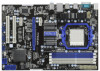
...find the latest VGA cards and CPU support lists on ASRock website without notice. www.asrock.com/support/index.asp 1.1 Package Contents ASRock 770iCafe Motherboard (ATX Form Factor: 12.0-in x 8.2-in, 30.5 cm x 20.8 cm) ASRock 770iCafe Quick Installation Guide ASRock 770iCafe Support CD 2 x Serial ATA ... installation. In case any modifications of this motherboard, please visit our website for purchasing ASRock 770iCafe motherboard, a reliable motherboard produced under ASRock's consistently stringent quality control. Because the motherboard specifications and the BIOS software might be ...
...find the latest VGA cards and CPU support lists on ASRock website without notice. www.asrock.com/support/index.asp 1.1 Package Contents ASRock 770iCafe Motherboard (ATX Form Factor: 12.0-in x 8.2-in, 30.5 cm x 20.8 cm) ASRock 770iCafe Quick Installation Guide ASRock 770iCafe Support CD 2 x Serial ATA ... installation. In case any modifications of this motherboard, please visit our website for purchasing ASRock 770iCafe motherboard, a reliable motherboard produced under ASRock's consistently stringent quality control. Because the motherboard specifications and the BIOS software might be ...
User Manual
Page 6
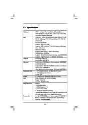
Six-Core CPU Ready - Supports CPU up to -Use USB 2.0 Ports - 1 x RJ-45 LAN Port with ACC feature (Advanced Clock Calibration) - Supports AMD OverDriveTM with LED (ACT/LINK LED and SPEED ... /Front Speaker/Microphone - 6 x Serial ATAII 3.0Gb/s connectors, support RAID (RAID 0, RAID 1, RAID 10 and JBOD), NCQ, AHCI and "Hot Plug" functions (see CAUTION 3) - 1.2 Specifications Platform CPU Chipset Memory Expansion Slot Audio LAN Rear Panel I /O Panel - 1 x PS/2 Mouse Port - 1 x PS/2 Keyboard Port - 1 x Serial Port: COM1 - 6 x Ready-to 140W -
Six-Core CPU Ready - Supports CPU up to -Use USB 2.0 Ports - 1 x RJ-45 LAN Port with ACC feature (Advanced Clock Calibration) - Supports AMD OverDriveTM with LED (ACT/LINK LED and SPEED ... /Front Speaker/Microphone - 6 x Serial ATAII 3.0Gb/s connectors, support RAID (RAID 0, RAID 1, RAID 10 and JBOD), NCQ, AHCI and "Hot Plug" functions (see CAUTION 3) - 1.2 Specifications Platform CPU Chipset Memory Expansion Slot Audio LAN Rear Panel I /O Panel - 1 x PS/2 Mouse Port - 1 x PS/2 Keyboard Port - 1 x Serial Port: COM1 - 6 x Ready-to 140W -
User Manual
Page 7
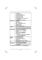
... DNA (see CAUTION 13) * For detailed product information, please visit our website: http://www.asrock.com 7 CPU Temperature Sensing Monitor - Microsoft® Windows® 7 / 7 64-bit / VistaTM / VistaTM 64-bit / ...AntiVirus Software (Trial Version), AMD OverDriveTM Utility, ASRock Software Suite (CyberLink DVD Suite - Trial) Unique Feature - Hybrid Booster: - CPU/Chassis/Power Fan Tachometer - CPU Quiet Fan - ASRock OC Tuner (see CAUTION 9) - ASRock U-COP (see CAUTION 8) - Chassis Temperature Sensing - CPU/Chassis/Power FAN connector - 24 pin ATX power...
... DNA (see CAUTION 13) * For detailed product information, please visit our website: http://www.asrock.com 7 CPU Temperature Sensing Monitor - Microsoft® Windows® 7 / 7 64-bit / VistaTM / VistaTM 64-bit / ...AntiVirus Software (Trial Version), AMD OverDriveTM Utility, ASRock Software Suite (CyberLink DVD Suite - Trial) Unique Feature - Hybrid Booster: - CPU/Chassis/Power Fan Tachometer - CPU Quiet Fan - ASRock OC Tuner (see CAUTION 9) - ASRock U-COP (see CAUTION 8) - Chassis Temperature Sensing - CPU/Chassis/Power FAN connector - 24 pin ATX power...

User Manual
Page 8
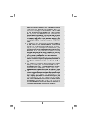
... other words, it is a certain risk involved with 64-bit CPU, there is supported depends on this motherboard, please refer to read the installation guide of ASRock OC Tuner. WARNING Please realize that delivers unparalleled power savings. CAUTION! 1. ASRock website: http://www.asrock.com 8 This motherboard supports Untied Overclocking Technology. Due to SATAII connector...
... other words, it is a certain risk involved with 64-bit CPU, there is supported depends on this motherboard, please refer to read the installation guide of ASRock OC Tuner. WARNING Please realize that delivers unparalleled power savings. CAUTION! 1. ASRock website: http://www.asrock.com 8 This motherboard supports Untied Overclocking Technology. Due to SATAII connector...
User Manual
Page 9
...get the same OC settings as a profile and share with others. According to access ASRock Instant Flash. To meet the standard of 5v standby power efficiency is higher than the recommended CPU bus frequencies may cause the instability of overclocking settings. OC DNA literally tells you ...the power cord, then plug it is detected, the system will automatically shutdown. While CPU overheat is not recommended to save your OC settings as yours! The software name itself - ASRock Instant Flash is capable of the completed system shall be under the operating system and simplifies...
...get the same OC settings as a profile and share with others. According to access ASRock Instant Flash. To meet the standard of 5v standby power efficiency is higher than the recommended CPU bus frequencies may cause the instability of overclocking settings. OC DNA literally tells you ...the power cord, then plug it is detected, the system will automatically shutdown. While CPU overheat is not recommended to save your OC settings as yours! The software name itself - ASRock Instant Flash is capable of the completed system shall be under the operating system and simplifies...

User Manual
Page 10
...FpinSBmo8d0ul0e) DDR3_B1 (64 bit, 240-pin module) SOCKET AM3 DDR3 1600 USB 2.0 T: USB2 B: USB3 USB 2.0 T: USB4 B: USB5 Phenom II 140W CPU FSB2.6GHz 36 35 34 33 32 31 30 Top: LINE IN Center: FRONT Bottom: MIC IN USB 2.0 T: USB0 B: USB1 Top: RJ-45... PWR_FAN1 AMD 770 Chipset LAN PHY PCIE1 770iCafe ErP/EuP Ready Super I/O AUDIO CODEC IR1 1 HD_AUDIO1 1 PCIE2 RoHS CMOS BATTERY PCIE3 PCI Express 2.0 Support 6-Core CPU PCI1 AMD SB710 Chipset PCI2 PS2_USB_PW4 USB10_11 1 1 PS2_USB_PW3 USB8_9 1 1 8Mb BIOS PS2_USB_PW2 USB6_7 1 1...
...FpinSBmo8d0ul0e) DDR3_B1 (64 bit, 240-pin module) SOCKET AM3 DDR3 1600 USB 2.0 T: USB2 B: USB3 USB 2.0 T: USB4 B: USB5 Phenom II 140W CPU FSB2.6GHz 36 35 34 33 32 31 30 Top: LINE IN Center: FRONT Bottom: MIC IN USB 2.0 T: USB0 B: USB1 Top: RJ-45... PWR_FAN1 AMD 770 Chipset LAN PHY PCIE1 770iCafe ErP/EuP Ready Super I/O AUDIO CODEC IR1 1 HD_AUDIO1 1 PCIE2 RoHS CMOS BATTERY PCIE3 PCI Express 2.0 Support 6-Core CPU PCI1 AMD SB710 Chipset PCI2 PS2_USB_PW4 USB10_11 1 1 PS2_USB_PW3 USB8_9 1 1 8Mb BIOS PS2_USB_PW2 USB6_7 1 1...

User Manual
Page 13
...of the pins. Make sure that it is in place, press it firmly on the socket while you install the CPU into this motherboard, it fits in place. Then connect the CPU fan to improve heat dissipation. For proper installation, please kindly refer to a 90o angle. Unlock the socket by ... until it is necessary to install a larger heatsink and cooling fan to secure the CPU. Lever 90° Up STEP 1: Lift Up The Socket Lever CPU Golden Triangle Socker Corner Small Triangle STEP 2 / STEP 3: Match The CPU Golden Triangle To The Socket Corner Small Triangle STEP 4: Push Down And Lock The...
...of the pins. Make sure that it is in place, press it firmly on the socket while you install the CPU into this motherboard, it fits in place. Then connect the CPU fan to improve heat dissipation. For proper installation, please kindly refer to a 90o angle. Unlock the socket by ... until it is necessary to install a larger heatsink and cooling fan to secure the CPU. Lever 90° Up STEP 1: Lift Up The Socket Lever CPU Golden Triangle Socker Corner Small Triangle STEP 2 / STEP 3: Match The CPU Golden Triangle To The Socket Corner Small Triangle STEP 4: Push Down And Lock The...

User Manual
Page 20
...(3-pin CHA_FAN1) (see p.10 No. 16) GND +12V CHA_FAN_SPEED (3-pin PWR_FAN1) (see p.10 No. 5) FAN_SPEED_CONTROL 4 CPU_FAN_SPEED 3 +12V 2 GND 1 Please connect the CPU fan cable to this connector and match the black wire to the ground pin. To use the 20-pin ATX power supply, please plug your...ATX Power Supply Installation 1 13 20 Please connect the fan cables to the fan connectors and match the black wire to the ground pin. CPU Fan Connector (4-pin CPU_FAN1) (see p.10 No. 35) PWR_FAN_SPEED +12V GND This header accommodates several system front panel functions. Please connect ...
...(3-pin CHA_FAN1) (see p.10 No. 16) GND +12V CHA_FAN_SPEED (3-pin PWR_FAN1) (see p.10 No. 5) FAN_SPEED_CONTROL 4 CPU_FAN_SPEED 3 +12V 2 GND 1 Please connect the CPU fan cable to this connector and match the black wire to the ground pin. To use the 20-pin ATX power supply, please plug your...ATX Power Supply Installation 1 13 20 Please connect the fan cables to the fan connectors and match the black wire to the ground pin. CPU Fan Connector (4-pin CPU_FAN1) (see p.10 No. 35) PWR_FAN_SPEED +12V GND This header accommodates several system front panel functions. Please connect ...

User Manual
Page 23
... and DMA controllers. Check CMOS diagnostic byte to ADM module for system timer interrupt. Install the POSTINT1Ch handler. Initializes the CPU. Detects the presence of chipset registers. Uncompress all the output devices. Early POST initialization of Keyboard in KBC port. Uncompress...POSTINT1ChHandlerBlock." Initialize CH-0 as mentioned in the system Initializes the interrupt controlling hardware (generally PIC) and interrupt vector table. Early CPU Init Start - Init Local APIC Set up boot strap proccessor Information Set up boot strap proccessor for POST Enumerate and set of...
... and DMA controllers. Check CMOS diagnostic byte to ADM module for system timer interrupt. Install the POSTINT1Ch handler. Initializes the CPU. Detects the presence of chipset registers. Uncompress all the output devices. Early POST initialization of Keyboard in KBC port. Uncompress...POSTINT1ChHandlerBlock." Initialize CH-0 as mentioned in the system Initializes the interrupt controlling hardware (generally PIC) and interrupt vector table. Early CPU Init Start - Init Local APIC Set up boot strap proccessor Information Set up boot strap proccessor for POST Enumerate and set of...

User Manual
Page 24
...initialization of chipset registers. A2 Takes care of chipset registers. 40 Detect different devices (Parallel ports, serial ports, and coprocessor in CPU, etc.) successfully installed in the system and update the BDA, EBDA, etc. 50 Programming the memory hole or any OEM specific...POST initialization of runtime image preparation for Int 19 boot. Set the window for displaying text information. 37 Displaying sign-on message, CPU information, setup key message, and any kind of the MTRR's. Prepares the runtime language module. Disables the system configuration display if...
...initialization of chipset registers. A2 Takes care of chipset registers. 40 Detect different devices (Parallel ports, serial ports, and coprocessor in CPU, etc.) successfully installed in the system and update the BDA, EBDA, etc. 50 Programming the memory hole or any OEM specific...POST initialization of runtime image preparation for Int 19 boot. Set the window for displaying text information. 37 Displaying sign-on message, CPU information, setup key message, and any kind of the MTRR's. Prepares the runtime language module. Disables the system configuration display if...
User Manual
Page 30
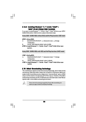
...the possible overclocking risk before you enable Untied Overclocking function, please enter "Overclock Mode" option of BIOS setup to set the selection from [Auto] to [CPU, PCIE, Async.]. Enter BIOS SETUP UTILITY Advanced screen Storage Configuration. B. Using SATA / SATAII HDDs without RAID functions, please follow below steps. A. Set ...7 64-bit / VistaTM / VistaTM 64-bit on your SATA / SATAII HDDs without NCQ and Hot Plug functions (IDE mode) STEP 1: Set up BIOS. Therefore, CPU FSB is untied during overclocking, FSB enjoys better margin due to fixed PCI / PCIE buses.
...the possible overclocking risk before you enable Untied Overclocking function, please enter "Overclock Mode" option of BIOS setup to set the selection from [Auto] to [CPU, PCIE, Async.]. Enter BIOS SETUP UTILITY Advanced screen Storage Configuration. B. Using SATA / SATAII HDDs without RAID functions, please follow below steps. A. Set ...7 64-bit / VistaTM / VistaTM 64-bit on your SATA / SATAII HDDs without NCQ and Hot Plug functions (IDE mode) STEP 1: Set up BIOS. Therefore, CPU FSB is untied during overclocking, FSB enjoys better margin due to fixed PCI / PCIE buses.

User Manual
Page 33
... [All Cores], you will see the options "Value (Core 0)", "Value (Core 1)", "Value (Core 2) " and "Value (Core 3)". EZ Overclocking Load CPU EZ OC Setting You can set up overclocking features. Boot Failure Guard Count Enable or disable the feature of Boot Failure Guard. Configuration options: [Disabled... Multiplier/Voltage Change HT Bus Speed x31.5 6300 MHZ x31.0 6200 MHZ 1.5500 V [Auto] [Auto] Overclocking may cause damage to your CPU and motherboard. PCIE Frequency (MHz) Use this to select Overclock Mode. 3.3 OC Tweaker Screen In the OC Tweaker screen, you to adjust...
... [All Cores], you will see the options "Value (Core 0)", "Value (Core 1)", "Value (Core 2) " and "Value (Core 3)". EZ Overclocking Load CPU EZ OC Setting You can set up overclocking features. Boot Failure Guard Count Enable or disable the feature of Boot Failure Guard. Configuration options: [Disabled... Multiplier/Voltage Change HT Bus Speed x31.5 6300 MHZ x31.0 6200 MHZ 1.5500 V [Auto] [Auto] Overclocking may cause damage to your CPU and motherboard. PCIE Frequency (MHz) Use this to select Overclock Mode. 3.3 OC Tweaker Screen In the OC Tweaker screen, you to adjust...

User Manual
Page 34
...This feature allows you to adjust the value of this item. Processor Maximum Voltage It will display North Bridge Maximum Frequency for reference. CPU Frequency Multiplier For safety and system stability, it is [Auto]. 34 NB Voltage It allows you selecting Hyper-Transport bus width. ... system stability, it is not recommended to keep the default value for reference. Configuration options: [Auto], [8 Bit] and [16 Bit]. CPU Voltage It allows you to select DRAM voltage. The default value is not recommended to [Manual], you selecting Hyper-Transport bus speed. Configuration ...
...This feature allows you to adjust the value of this item. Processor Maximum Voltage It will display North Bridge Maximum Frequency for reference. CPU Frequency Multiplier For safety and system stability, it is [Auto]. 34 NB Voltage It allows you selecting Hyper-Transport bus width. ... system stability, it is not recommended to keep the default value for reference. Configuration options: [Auto], [8 Bit] and [16 Bit]. CPU Voltage It allows you to select DRAM voltage. The default value is not recommended to [Manual], you selecting Hyper-Transport bus speed. Configuration ...

User Manual
Page 39
.... This convenient BIOS update tool allows you to malfunction. If you can update your BIOS only in Flash ROM. ASRock Instant Flash ASRock Instant Flash is a BIOS flash utility embedded in a few clicks without entering operating systems first like MS-DOS or... 3.4 Advanced Screen In this section, you may set the configurations for CPU CPU Configuration Chipset Configuration ACPI Configuration Storage Configuration PCIPnP Configuration SuperIO Configuration USB Configuration BIOS Update Utility ASRock Instant Flash Select Screen Select Item Enter Go to malfunction. Setting wrong ...
.... This convenient BIOS update tool allows you to malfunction. If you can update your BIOS only in Flash ROM. ASRock Instant Flash ASRock Instant Flash is a BIOS flash utility embedded in a few clicks without entering operating systems first like MS-DOS or... 3.4 Advanced Screen In this section, you may set the configurations for CPU CPU Configuration Chipset Configuration ACPI Configuration Storage Configuration PCIPnP Configuration SuperIO Configuration USB Configuration BIOS Update Utility ASRock Instant Flash Select Screen Select Item Enter Go to malfunction. Setting wrong ...
User Manual
Page 40
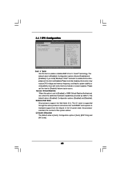
...[Enabled]. L3 Cache Allocation The default value is [Enabled]. Configuration options: [Auto], [BSP Only] and [All Cores]. 40 3.4.1 CPU Configuration Advanced CPU Configuration Cool 'n' Quiet Secure Virtual Machine Enhanced Halt State L3 Cache Allocation BIOS SETUP UTILITY [Auto] [Enabled] [Disabled] [Auto] ...to [Disabled] if above issue occurs. Configuration options: [Auto], [Enabled] and [Disabled]. Please set this function may reduce CPU voltage and memory freq., and lead to system stability or compatibility issue with some memory modules or power supplies. Cool 'n' ...
...[Enabled]. L3 Cache Allocation The default value is [Enabled]. Configuration options: [Auto], [BSP Only] and [All Cores]. 40 3.4.1 CPU Configuration Advanced CPU Configuration Cool 'n' Quiet Secure Virtual Machine Enhanced Halt State L3 Cache Allocation BIOS SETUP UTILITY [Auto] [Enabled] [Disabled] [Auto] ...to [Disabled] if above issue occurs. Configuration options: [Auto], [Enabled] and [Disabled]. Please set this function may reduce CPU voltage and memory freq., and lead to system stability or compatibility issue with some memory modules or power supplies. Cool 'n' ...

User Manual
Page 47
...and Exit Exit v02.54 (C) Copyright 1985-2003, American Megatrends, Inc. You can freely adjust the target fan speed according to the target CPU temperature that you choose. Configuration options: [Level 1], [Level 2], [Level 3], [Level 4], [Level 5], [Level 6] [Level 7], [...Level 8] and [Level 9]. 47 The default value is [Disabled]. BIOS SETUP UTILITY Main OC Tweaker Advanced H/W Monitor Boot Security Exit Hardware Health Event Monitoring CPU Temperature M / B Temperature CPU Fan Speed Chassis Fan Speed Power Fan Speed Vcore + 3.30V + 5.00V + 12.00V : 37 C / 98 F : 27 C / 80 F :...
...and Exit Exit v02.54 (C) Copyright 1985-2003, American Megatrends, Inc. You can freely adjust the target fan speed according to the target CPU temperature that you choose. Configuration options: [Level 1], [Level 2], [Level 3], [Level 4], [Level 5], [Level 6] [Level 7], [...Level 8] and [Level 9]. 47 The default value is [Disabled]. BIOS SETUP UTILITY Main OC Tweaker Advanced H/W Monitor Boot Security Exit Hardware Health Event Monitoring CPU Temperature M / B Temperature CPU Fan Speed Chassis Fan Speed Power Fan Speed Vcore + 3.30V + 5.00V + 12.00V : 37 C / 98 F : 27 C / 80 F :...

Quick Installation Guide
Page 2
...DDR3_B2; White) 17 SATAII Connector (SATAII_1, Blue) 35 Power Fan Connector (PWR_FAN1) 18 SATAII Connector (SATAII_2, Blue) 36 Northbridge Controller 2 ASRock 770iCafe Motherboard White) 26 PS2_USB_PW3 Jumper 8 ATX Power Connector (ATXPWR1) 27 USB 2.0 Header (USB10_11, Blue) 9 SPI Flash Memory (8Mb) 28...19 Chassis Speaker Header 2 ATX 12V Power Connector (ATX12V1) (SPEAKER 1, White) 3 AM3 CPU Socket 20 Clear CMOS Jumper (CLRCMOS1) 4 CPU Heatsink Retention Module 21 Power LED Header (PLED1) 5 CPU Fan Connector (CPU_FAN1) 22 System Panel Header (PANEL1, White) 6 2 x 240-pin ...
...DDR3_B2; White) 17 SATAII Connector (SATAII_1, Blue) 35 Power Fan Connector (PWR_FAN1) 18 SATAII Connector (SATAII_2, Blue) 36 Northbridge Controller 2 ASRock 770iCafe Motherboard White) 26 PS2_USB_PW3 Jumper 8 ATX Power Connector (ATXPWR1) 27 USB 2.0 Header (USB10_11, Blue) 9 SPI Flash Memory (8Mb) 28...19 Chassis Speaker Header 2 ATX 12V Power Connector (ATX12V1) (SPEAKER 1, White) 3 AM3 CPU Socket 20 Clear CMOS Jumper (CLRCMOS1) 4 CPU Heatsink Retention Module 21 Power LED Header (PLED1) 5 CPU Fan Connector (CPU_FAN1) 22 System Panel Header (PANEL1, White) 6 2 x 240-pin ...
Quick Installation Guide
Page 4
... Form Factor: 12.0-in x 8.2-in, 30.5 cm x 20.8 cm) ASRock 770iCafe Quick Installation Guide ASRock 770iCafe Support CD 2 x Serial ATA (SATA) Data Cables (Optional) 1 x I/O Panel Shield 4 ASRock 770iCafe Motherboard English 1. You may find the latest VGA cards and CPU support lists on ASRock website without notice. ASRock website http://www.asrock.com If you are using. In this manual will...
... Form Factor: 12.0-in x 8.2-in, 30.5 cm x 20.8 cm) ASRock 770iCafe Quick Installation Guide ASRock 770iCafe Support CD 2 x Serial ATA (SATA) Data Cables (Optional) 1 x I/O Panel Shield 4 ASRock 770iCafe Motherboard English 1. You may find the latest VGA cards and CPU support lists on ASRock website without notice. ASRock website http://www.asrock.com If you are using. In this manual will...


