
User Manual
Page 10
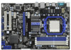
... MIC IN USB 2.0 T: USB0 B: USB1 Top: RJ-45 PWR_FAN1 AMD 770 Chipset LAN PHY PCIE1 770iCafe ErP/EuP Ready Super I/O AUDIO CODEC IR1 1 HD_AUDIO1 1 PCIE2 RoHS CMOS BATTERY PCIE3 PCI Express 2.0 Support 6-Core CPU PCI1 AMD SB710 Chipset PCI2 PS2_USB_PW4 USB10_11 1 1 PS2_USB_PW3 ... 13 14 15 1 PS2_USB_PW1 Jumper 19 Chassis Speaker Header 2 ATX 12V Power Connector (ATX12V1) (SPEAKER 1, White) 3 AM3 CPU Socket 20 Clear CMOS Jumper (CLRCMOS1) 4 CPU Heatsink Retention Module 21 Power LED Header (PLED1) 5 CPU Fan Connector (CPU_FAN1) 22 System Panel Header (PANEL1, White...
... MIC IN USB 2.0 T: USB0 B: USB1 Top: RJ-45 PWR_FAN1 AMD 770 Chipset LAN PHY PCIE1 770iCafe ErP/EuP Ready Super I/O AUDIO CODEC IR1 1 HD_AUDIO1 1 PCIE2 RoHS CMOS BATTERY PCIE3 PCI Express 2.0 Support 6-Core CPU PCI1 AMD SB710 Chipset PCI2 PS2_USB_PW4 USB10_11 1 1 PS2_USB_PW3 ... 13 14 15 1 PS2_USB_PW1 Jumper 19 Chassis Speaker Header 2 ATX 12V Power Connector (ATX12V1) (SPEAKER 1, White) 3 AM3 CPU Socket 20 Clear CMOS Jumper (CLRCMOS1) 4 CPU Heatsink Retention Module 21 Power LED Header (PLED1) 5 CPU Fan Connector (CPU_FAN1) 22 System Panel Header (PANEL1, White...

User Manual
Page 17
... pin3 to enable +5VSB (standby) for USB6_7 wake up events. Jumper Setting PS2_USB_PW1 1_2 2_3 Short pin2, pin3 to clear the data in CMOS includes system setup information such as system password, date, time, and system setup parameters. PS2_USB_PW4 (see p.10, No. 20) 1_2 2_3 Default Clear... CMOS Note: CLRCMOS1 allows you to enable (see p.10, No. 24) +5V +5VSB +5VSB (standby) for USB8_9 wake up events. When the jumper ...
... pin3 to enable +5VSB (standby) for USB6_7 wake up events. Jumper Setting PS2_USB_PW1 1_2 2_3 Short pin2, pin3 to clear the data in CMOS includes system setup information such as system password, date, time, and system setup parameters. PS2_USB_PW4 (see p.10, No. 20) 1_2 2_3 Default Clear... CMOS Note: CLRCMOS1 allows you to enable (see p.10, No. 24) +5V +5VSB +5VSB (standby) for USB8_9 wake up events. When the jumper ...
User Manual
Page 18
..., No. 14) SATAII interface allows up the system first, and then shut it down before you do not clear the CMOS right after you update the BIOS. However, please do the clear-CMOS action. 2.6 Onboard Headers and Connectors Onboard headers and connectors are three USB 2.0 headers on the I/O panel, there are NOT...
..., No. 14) SATAII interface allows up the system first, and then shut it down before you do not clear the CMOS right after you update the BIOS. However, please do the clear-CMOS action. 2.6 Onboard Headers and Connectors Onboard headers and connectors are three USB 2.0 headers on the I/O panel, there are NOT...

User Manual
Page 22
... keyboard controller. Leaves all RAM below for future use in Bootblock code. Perform keyboard controller BAT test. Verify that flat mode is stored in scratch CMOS. Main BIOS checksum is disabled. CPUID information is enabled. NMI is tested. Adjust policies and cache first 8MB. The Bootblock-Runtime interface module is moved...
... keyboard controller. Leaves all RAM below for future use in Bootblock code. Perform keyboard controller BAT test. Verify that flat mode is stored in scratch CMOS. Main BIOS checksum is disabled. CPUID information is enabled. NMI is tested. Adjust policies and cache first 8MB. The Bootblock-Runtime interface module is moved...

User Manual
Page 23
...devices. Early POST initialization of checkpoints during the POST portion of different Input Devices. Allocate memory for more information. Initialized CMOS as system timer. Initializes data variables that have optional ROMs. Initializes all available language, BIOS logo, and Silent logo ...modules. Initializes different devices through DIM. Verify CMOS checksum manually by reading storage area. See DIM Code Checkpoints section of KB/MS using AMI KB-5. Initialize status register ...
...devices. Early POST initialization of checkpoints during the POST portion of different Input Devices. Allocate memory for more information. Initialized CMOS as system timer. Initializes data variables that have optional ROMs. Initializes all available language, BIOS logo, and Silent logo ...modules. Initializes different devices through DIM. Verify CMOS checksum manually by reading storage area. See DIM Code Checkpoints section of KB/MS using AMI KB-5. Initialize status register ...

User Manual
Page 24
.... Also, Check for DEL or ESC keys to the user and gets the user response for error. 87 Execute BIOS setup if needed . 52 Updates CMOS memory size from base memory. 60 Initializes NUM-LOCK status and programs the KBD typematic rate. 75 Initialize Int-13 and prepare for ACPI. 00...
.... Also, Check for DEL or ESC keys to the user and gets the user response for error. 87 Execute BIOS setup if needed . 52 Updates CMOS memory size from base memory. 60 Initializes NUM-LOCK status and programs the KBD typematic rate. 75 Initialize Int-13 and prepare for ACPI. 00...

Quick Installation Guide
Page 2
... 17 SATAII Connector (SATAII_1, Blue) 35 Power Fan Connector (PWR_FAN1) 18 SATAII Connector (SATAII_2, Blue) 36 Northbridge Controller 2 ASRock 770iCafe Motherboard White) 15 SATAII Connector (SATAII_3, Blue) 33 PCI Express x16 Slot (PCIE2; Motherboard Layout English 1 PS2_USB_PW1 Jumper 19 ...Chassis Speaker Header 2 ATX 12V Power Connector (ATX12V1) (SPEAKER 1, White) 3 AM3 CPU Socket 20 Clear CMOS Jumper (CLRCMOS1) 4 CPU Heatsink Retention Module 21 Power LED Header (PLED1) 5 CPU Fan Connector (CPU_FAN1) 22 System Panel Header (PANEL1...
... 17 SATAII Connector (SATAII_1, Blue) 35 Power Fan Connector (PWR_FAN1) 18 SATAII Connector (SATAII_2, Blue) 36 Northbridge Controller 2 ASRock 770iCafe Motherboard White) 15 SATAII Connector (SATAII_3, Blue) 33 PCI Express x16 Slot (PCIE2; Motherboard Layout English 1 PS2_USB_PW1 Jumper 19 ...Chassis Speaker Header 2 ATX 12V Power Connector (ATX12V1) (SPEAKER 1, White) 3 AM3 CPU Socket 20 Clear CMOS Jumper (CLRCMOS1) 4 CPU Heatsink Retention Module 21 Power LED Header (PLED1) 5 CPU Fan Connector (CPU_FAN1) 22 System Panel Header (PANEL1...

Quick Installation Guide
Page 14
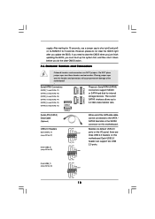
.../2 or USB wake up events. Note: To select +5VSB, it requires 2 Amp and higher standby current provided by power supply. The data in CMOS. The illustration shows a 3-pin jumper whose pin1 and pin2 are setup. Note: To select +5VSB, it requires 2 Amp and higher standby current provided... jumper is "Short". PS2_USB_PW4 Short pin2, pin3 to default setup, please turn off the computer and unplug the power cord from the power 14 ASRock 770iCafe Motherboard When the jumper cap is placed on these 2 pins. 2.5 Jumpers Setup The illustration shows how jumpers are "Short" when jumper cap is...
.../2 or USB wake up events. Note: To select +5VSB, it requires 2 Amp and higher standby current provided by power supply. The data in CMOS. The illustration shows a 3-pin jumper whose pin1 and pin2 are setup. Note: To select +5VSB, it requires 2 Amp and higher standby current provided... jumper is "Short". PS2_USB_PW4 Short pin2, pin3 to default setup, please turn off the computer and unplug the power cord from the power 14 ASRock 770iCafe Motherboard When the jumper cap is placed on these 2 pins. 2.5 Jumpers Setup The illustration shows how jumpers are "Short" when jumper cap is...

Quick Installation Guide
Page 15
... (9-pin USB8_9) (see p.2, No. 18) or SATA hard disk for 15 seconds, use a jumper cap to clear the CMOS when you just finish updating the BIOS, you must boot up to the SATA / SATAII hard disk or the SATAII connector on.... English (9-pin USB6_7) (see p.2, No. 15) storage devices. However, please do not clear the CMOS right after you do the clear-CMOS action. 2.6 Onboard Headers and Connectors Onboard headers and connectors are three USB 2.0 headers on CLRCMOS1 for 5... on this motherboard. After waiting for internal (SATAII_3: see p.2 No. 23) 15 ASRock 770iCafe Motherboard
... (9-pin USB8_9) (see p.2, No. 18) or SATA hard disk for 15 seconds, use a jumper cap to clear the CMOS when you just finish updating the BIOS, you must boot up to the SATA / SATAII hard disk or the SATAII connector on.... English (9-pin USB6_7) (see p.2, No. 15) storage devices. However, please do not clear the CMOS right after you do the clear-CMOS action. 2.6 Onboard Headers and Connectors Onboard headers and connectors are three USB 2.0 headers on CLRCMOS1 for 5... on this motherboard. After waiting for internal (SATAII_3: see p.2 No. 23) 15 ASRock 770iCafe Motherboard

Quick Installation Guide
Page 19
...RTC and keyboard controller. Store the Uncompressed pointer for reading the Dr. Debug codes. Restore CPUID value back into register. English 19 ASRock 770iCafe Motherboard 2.7 Dr. Debug Dr. Debug is used to flat mode with 4GB limit and GA20 enabled. Early super I/O initialization is... memory sizing module. Adjust policies and cache first 8MB. Restore CPUID value back into register. CPUID information is stored in scratch CMOS. The following table describes the type of checkpoints that flat mode is necessary, control flows to BIOS POST (ExecutePOSTKernel). Perform keyboard...
...RTC and keyboard controller. Store the Uncompressed pointer for reading the Dr. Debug codes. Restore CPUID value back into register. English 19 ASRock 770iCafe Motherboard 2.7 Dr. Debug Dr. Debug is used to flat mode with 4GB limit and GA20 enabled. Early super I/O initialization is... memory sizing module. Adjust policies and cache first 8MB. Restore CPUID value back into register. CPUID information is stored in scratch CMOS. The following table describes the type of checkpoints that flat mode is necessary, control flows to BIOS POST (ExecutePOSTKernel). Perform keyboard...

Quick Installation Guide
Page 20
... in the system Initializes the interrupt controlling hardware (generally PIC) and interrupt vector table. The POST code checkpoints are based on CMOS setup questions. Do R/W test to "POSTINT1ChHandlerBlock." The BAT test is OK. Early CPU Init Start - Disable Cache - Detects... Initializes both the 8259 compatible PICs in KBC port. Testing and initialization of PS/2 mouse. Initializes different devices. ASRock 770iCafe Motherboard English If the CMOS checksum is being done on POST entry and GPNV area. Also initialize BIOS modules on KBC. Initializes the CPU...
... in the system Initializes the interrupt controlling hardware (generally PIC) and interrupt vector table. The POST code checkpoints are based on CMOS setup questions. Do R/W test to "POSTINT1ChHandlerBlock." The BAT test is OK. Early CPU Init Start - Disable Cache - Detects... Initializes both the 8259 compatible PICs in KBC port. Testing and initialization of PS/2 mouse. Initializes different devices. ASRock 770iCafe Motherboard English If the CMOS checksum is being done on POST entry and GPNV area. Also initialize BIOS modules on KBC. Initializes the CPU...

Quick Installation Guide
Page 21
A7 Displays the system configuration screen if enabled. English 21 ASRock 770iCafe Motherboard Also, Check for error. 87 Execute BIOS setup if needed / requested. 8C Late POST initialization of chipset registers. 8D Build ACPI tables (if ACPI ... an adjustment in system RAM size if needed . A2 Takes care of runtime image preparation for user input at config display if needed . 52 Updates CMOS memory size from base memory. 60 Initializes NUM-LOCK status and programs the KBD typematic rate. 75 Initialize Int-13 and prepare for IPL detection...
A7 Displays the system configuration screen if enabled. English 21 ASRock 770iCafe Motherboard Also, Check for error. 87 Execute BIOS setup if needed / requested. 8C Late POST initialization of chipset registers. 8D Build ACPI tables (if ACPI ... an adjustment in system RAM size if needed . A2 Takes care of runtime image preparation for user input at config display if needed . 52 Updates CMOS memory size from base memory. 60 Initializes NUM-LOCK status and programs the KBD typematic rate. 75 Initialize Int-13 and prepare for IPL detection...

