
User Guide
Page 2
...work (such as such is completely chlorine-free. Ensuring that comes from time to time without written permission from 3Com Corporation. 3Com Corporation reserves the right to revise this documentation and to make changes in all operations. ■ Reducing the waste...translation, transformation, or adaptation) without obligation on a continual basis. it is environmentally-friendly, and the inks are registered trademarks of 3Com Corporation. IEEE and 802 are registered trademarks of Microsoft Corporation. The varnish is furnished under a license agreement included with , this...
...work (such as such is completely chlorine-free. Ensuring that comes from time to time without written permission from 3Com Corporation. 3Com Corporation reserves the right to revise this documentation and to make changes in all operations. ■ Reducing the waste...translation, transformation, or adaptation) without obligation on a continual basis. it is environmentally-friendly, and the inks are registered trademarks of 3Com Corporation. IEEE and 802 are registered trademarks of Microsoft Corporation. The varnish is furnished under a license agreement included with , this...
User Guide
Page 3
... 1 INTRODUCING THE BASELINE SWITCH Overview of the Baseline Switch 7 Features and Capabilities 7 Autosensing of MDI/MDIX Connections 7 Autonegotiating 10/100/1000 Mbps Ports 7 SFP Ports 7 Physical Features 8 Front Panel 8 Rear Panel 11 Package Contents 11 2 INSTALLING THE SWITCH Before You Begin 13 Positioning the Switch 13 Rack-Mounting or...14 Using the Mounting Kit 14 Montagesatz Anweisungen 15 Placing Units On Top of Each Other 15 Supplying Power to the Switch 16 Checking for Correct Operation 16 Connecting a Network Device 17 Using SFP Transceivers 18 Approved SFP Transceivers 18 Inserting ...
... 1 INTRODUCING THE BASELINE SWITCH Overview of the Baseline Switch 7 Features and Capabilities 7 Autosensing of MDI/MDIX Connections 7 Autonegotiating 10/100/1000 Mbps Ports 7 SFP Ports 7 Physical Features 8 Front Panel 8 Rear Panel 11 Package Contents 11 2 INSTALLING THE SWITCH Before You Begin 13 Positioning the Switch 13 Rack-Mounting or...14 Using the Mounting Kit 14 Montagesatz Anweisungen 15 Placing Units On Top of Each Other 15 Supplying Power to the Switch 16 Checking for Correct Operation 16 Connecting a Network Device 17 Using SFP Transceivers 18 Approved SFP Transceivers 18 Inserting ...

User Guide
Page 4
Changing the Admin Password 28 Modifying the IP Address Settings 29 Automatic IP Configuration 29 Setting the IP Address 30 Configuring Port Settings 31 Basic Port Configuration 31 Advanced Port Configuration 33 Configuring VLANs 33 Creating a VLAN 34 Sample VLAN Configurations 35 Removing a VLAN 37 Configuring Link Aggregation 37 Guidelines for Creating Aggregated Links 38 Defining the Members of an Aggregated Link 38 Modifying Settings and Deleting an Aggregated Link 39 Viewing the Trunk Summary 39 Viewing Statistics 40 Mirroring Port Traffic 41 Running Cable Diagnostic 42 Using the System ...
Changing the Admin Password 28 Modifying the IP Address Settings 29 Automatic IP Configuration 29 Setting the IP Address 30 Configuring Port Settings 31 Basic Port Configuration 31 Advanced Port Configuration 33 Configuring VLANs 33 Creating a VLAN 34 Sample VLAN Configurations 35 Removing a VLAN 37 Configuring Link Aggregation 37 Guidelines for Creating Aggregated Links 38 Defining the Members of an Aggregated Link 38 Modifying Settings and Deleting an Aggregated Link 39 Viewing the Trunk Summary 39 Viewing Statistics 40 Mirroring Port Traffic 41 Running Cable Diagnostic 42 Using the System ...

User Guide
Page 5
... is referred to as Twisted Pair Cables throughout this guide. Category 3 and Category 5 Twisted Pair Cables are linked with this 3Com Baseline Switch 2816-SFP/2824-SFP Plus and contains information that differs from the information in this guide, follow the information in Adobe Acrobat Reader Portable...must type something, and then press Return or Enter. Keyboard key names If you see the word "enter" in this guide, the 3Com Baseline Switch 2816/2824-SFP Plus is intended for use by those responsible for installing and setting up network equipment. Conventions Table 1 and Table 2 ...
... is referred to as Twisted Pair Cables throughout this guide. Category 3 and Category 5 Twisted Pair Cables are linked with this 3Com Baseline Switch 2816-SFP/2824-SFP Plus and contains information that differs from the information in this guide, follow the information in Adobe Acrobat Reader Portable...must type something, and then press Return or Enter. Keyboard key names If you see the word "enter" in this guide, the 3Com Baseline Switch 2816/2824-SFP Plus is intended for use by those responsible for installing and setting up network equipment. Conventions Table 1 and Table 2 ...
User Guide
Page 6
... perform tasks using the Web interface. ■ Release Notes - They will help make our documentation more useful to this guide, each 3Com Baseline Switch 2816-SFP/2824-SFP Plus documentation set includes the following information when commenting: ■ Document title ■ Document part number (on the ...title page) ■ Page number (if appropriate) Example: ■ 3Com Baseline Switch 2816-SFP/2824-SFP Plus User Guide ■ Part Number DUA1648-5AAA03 ■ Page 24 Do not use this document to 3Com at the place where it is defined in italics Description Italics are very ...
... perform tasks using the Web interface. ■ Release Notes - They will help make our documentation more useful to this guide, each 3Com Baseline Switch 2816-SFP/2824-SFP Plus documentation set includes the following information when commenting: ■ Document title ■ Document part number (on the ...title page) ■ Page number (if appropriate) Example: ■ 3Com Baseline Switch 2816-SFP/2824-SFP Plus User Guide ■ Part Number DUA1648-5AAA03 ■ Page 24 Do not use this document to 3Com at the place where it is defined in italics Description Italics are very ...

User Guide
Page 7
.../100/1000 Mbps port automatically determines the speed and duplex mode of the 3Com® Baseline Switch 2816/2824-SFP Plus. Any port can therefore be used to connect to fiber-based Gigabit media. This allows you get to -use . The Switch is necessary. The 1000BASE-T ports also support automatic 10/100/1000 Mbps...Ports The four SFP ports support fiber Gigabit Ethernet short-wave (SX) and long-wave (LX) SFP transceivers in full duplex mode. Overview of the Baseline Switch The 3Com Baseline Switch 2816-SFP/2824-SFP Plus is ideal for users who want the high-speed performance of 10/100/1000...
.../100/1000 Mbps port automatically determines the speed and duplex mode of the 3Com® Baseline Switch 2816/2824-SFP Plus. Any port can therefore be used to connect to fiber-based Gigabit media. This allows you get to -use . The Switch is necessary. The 1000BASE-T ports also support automatic 10/100/1000 Mbps...Ports The four SFP ports support fiber Gigabit Ethernet short-wave (SX) and long-wave (LX) SFP transceivers in full duplex mode. Overview of the Baseline Switch The 3Com Baseline Switch 2816-SFP/2824-SFP Plus is ideal for users who want the high-speed performance of 10/100/1000...
User Guide
Page 8
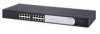
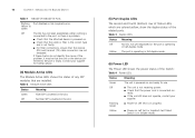
... de données. When an SFP port is in "Front Panel" below and "Rear Panel" on page 11. Figure 1 Front and Rear Panels (2816-SFP) 1 1 9 8 4 5 12 13 Baseline Switch 2816-SFP Plus Module Present 8 16 Link/Activity : Green = 1000M, Yellow = 10/1000M, Flash = Activity, Duplex : On = Full, Off = Half 3C16485A 2 4 53 6 7 9 Front Panel...
... de données. When an SFP port is in "Front Panel" below and "Rear Panel" on page 11. Figure 1 Front and Rear Panels (2816-SFP) 1 1 9 8 4 5 12 13 Baseline Switch 2816-SFP Plus Module Present 8 16 Link/Activity : Green = 1000M, Yellow = 10/1000M, Flash = Activity, Duplex : On = Full, Off = Half 3C16485A 2 4 53 6 7 9 Front Panel...

User Guide
Page 9
... Status Meaning Green The link is a configurable option). (2) SFP Ports The Small Form Factor Pluggable (SFP) ports are numbered 13 to 16 (2816-SFP) and 21 to read their speed and duplex mode (half duplex or full duplex for 10BASE-T and 100BASE-TX, full duplex only for ... The following table lists LEDs visible on the Yellow port at 1000 Mbps. CAUTION: The Switch supports full duplex auto-negotiation. In such a configuration, you may notice some degradation of network performance. 3Com recommends that you use devices that are capable of auto-negotiation (and that you the flexibility...
... Status Meaning Green The link is a configurable option). (2) SFP Ports The Small Form Factor Pluggable (SFP) ports are numbered 13 to 16 (2816-SFP) and 21 to read their speed and duplex mode (half duplex or full duplex for 10BASE-T and 100BASE-TX, full duplex only for ... The following table lists LEDs visible on the Yellow port at 1000 Mbps. CAUTION: The Switch supports full duplex auto-negotiation. In such a configuration, you may notice some degradation of network performance. 3Com recommends that you use devices that are capable of auto-negotiation (and that you the flexibility...
User Guide
Page 10
...swapped. Flashing Green ■ Power-on and ready for further advice. (4) Module Active LEDs The Module Active LEDs shows the status of the Switch: Table 4 Power LEDs Status Meaning Green The unit is powered on self test is in the slot. (5) Port Duplex LEDs The second and ...Power-on . ■ Check that the cable or fiber is the correct type and is operating in the slot. 10 CHAPTER 1: INTRODUCING THE BASELINE SWITCH Table 1 10BASE-T/100BASE-TX Ports Flashing Port disabled or link loopback error. If these checks do not identify the cause of the related ports.
...swapped. Flashing Green ■ Power-on and ready for further advice. (4) Module Active LEDs The Module Active LEDs shows the status of the Switch: Table 4 Power LEDs Status Meaning Green The unit is powered on self test is in the slot. (5) Port Duplex LEDs The second and ...Power-on . ■ Check that the cable or fiber is the correct type and is operating in the slot. 10 CHAPTER 1: INTRODUCING THE BASELINE SWITCH Table 1 10BASE-T/100BASE-TX Ports Flashing Port disabled or link loopback error. If these checks do not identify the cause of the related ports.

User Guide
Page 11
...■ One mounting kit ■ 3Com Installation CD ■ This User Guide ■ Warranty flyer If any of the unit. Package Contents 11 Package Contents Before installing and using the Switch, verify that is complete. If you recover the Switch, otherwise your configuration settings before you...to the supply voltage. Refer to the factory default settings if, for details. CAUTION: 3Com recommends that the pads locate with four self-adhesive rubber pads. This returns the Switch to "Configuration" on top of the lower unit, ensuring that you back up your configuration...
...■ One mounting kit ■ 3Com Installation CD ■ This User Guide ■ Warranty flyer If any of the unit. Package Contents 11 Package Contents Before installing and using the Switch, verify that is complete. If you recover the Switch, otherwise your configuration settings before you...to the supply voltage. Refer to the factory default settings if, for details. CAUTION: 3Com recommends that the pads locate with four self-adhesive rubber pads. This returns the Switch to "Configuration" on top of the lower unit, ensuring that you back up your configuration...

User Guide
Page 12
12 CHAPTER 1: INTRODUCING THE BASELINE SWITCH
12 CHAPTER 1: INTRODUCING THE BASELINE SWITCH

User Guide
Page 13
... Using SFP Transceivers ■ Performing Spot Checks Before You Begin WARNING: Safety Information. Before installing or removing any components from the Switch or carrying out any maintenance procedures, read the safety information provided in a standard 19-inch equipment rack. It covers the following... di manutenzione, leggere le informazioni di sicurezza riportate nell'Appendice B (Appendix C) della presente guida per l'utente. Positioning the Switch The Switch is suitable for use in an office environment where it can be free-standing or mounted in Appendix C of this guide....
... Using SFP Transceivers ■ Performing Spot Checks Before You Begin WARNING: Safety Information. Before installing or removing any components from the Switch or carrying out any maintenance procedures, read the safety information provided in a standard 19-inch equipment rack. It covers the following... di manutenzione, leggere le informazioni di sicurezza riportate nell'Appendice B (Appendix C) della presente guida per l'utente. Positioning the Switch The Switch is suitable for use in an office environment where it can be free-standing or mounted in Appendix C of this guide....
User Guide
Page 14
...should take note of the guidelines given in a free-standing stack of the case is not restricted (3Com recommends that the unit is not available, try to a ground point. Electromagnetic fields can interfere with the Switch. A mounting kit, containing two mounting brackets and four screws, is 1U high and will fit ... or moisture cannot enter the case of the unit. ■ Air flow around the unit and through the vents in the side of different size Baseline or Superstack® 3 units, the smaller units must be installed above the larger ones. Do not have a free-standing stack of the unit ...
...should take note of the guidelines given in a free-standing stack of the case is not restricted (3Com recommends that the unit is not available, try to a ground point. Electromagnetic fields can interfere with the Switch. A mounting kit, containing two mounting brackets and four screws, is 1U high and will fit ... or moisture cannot enter the case of the unit. ■ Air flow around the unit and through the vents in the side of different size Baseline or Superstack® 3 units, the smaller units must be installed above the larger ones. Do not have a free-standing stack of the unit ...
User Guide
Page 16
...turns yellow after POST. Table 5 Possible Power LED Colors After POST Color State Green The unit is intended to "(6) Power LED" on the Switch, it is called "power cycling". Supplying Power to "(8) Power Supply" on page 11 for Correct Operation After you install power conditioning, especially in... and electrical storms. The unit is powered on , the Power LED lights up with the recesses of the lower unit. Refer to the Switch Power problems can be grounded. Table 5Table 5 summarizes the possible colors for use . Installing proper grounding helps to power on top of each...
...turns yellow after POST. Table 5 Possible Power LED Colors After POST Color State Green The unit is intended to "(6) Power LED" on the Switch, it is called "power cycling". Supplying Power to "(8) Power Supply" on page 11 for Correct Operation After you install power conditioning, especially in... and electrical storms. The unit is powered on , the Power LED lights up with the recesses of the lower unit. Refer to the Switch Power problems can be grounded. Table 5Table 5 summarizes the possible colors for use . Installing proper grounding helps to power on top of each...
User Guide
Page 17
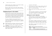
... for assistance. If these do not resolve the issue: ■ Check the 3Com Knowledgebase for each connection is in fail-safe mode. Figure 3 Connecting Devices to the Switch Baseline 10/100 Switch Endstations on switched 100 Mbps connections Baseline 10/100 Switch Endstations on switched 100 Mbps connections BaselineBSawsietclihne28S1w6i/t2ch82242-5S0FP Plus 1000 Mbps copper or F iber connection...
... for assistance. If these do not resolve the issue: ■ Check the 3Com Knowledgebase for each connection is in fail-safe mode. Figure 3 Connecting Devices to the Switch Baseline 10/100 Switch Endstations on switched 100 Mbps connections Baseline 10/100 Switch Endstations on switched 100 Mbps connections BaselineBSawsietclihne28S1w6i/t2ch82242-5S0FP Plus 1000 Mbps copper or F iber connection...
User Guide
Page 18
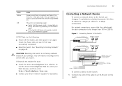
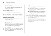
...is faulty, it will not recognize it. 18 CHAPTER 2: INSTALLING THE SWITCH 2 Connect the other end to power off the Switch. Using SFP Transceivers The following list of approved SFP transceivers for the Switch on the 3Com Corporation World Wide Web site, enter this URL into any SFP port without... fiber using Category 5e or 6 cables. Use this transceiver to connect the Switch directly to insert and remove an SFP transceiver from and insert them into your Internet browser: www.3com.com 3Com recommends using 3Com SFPs on page 49. Ensure the wire release lever is correct at the ...
...is faulty, it will not recognize it. 18 CHAPTER 2: INSTALLING THE SWITCH 2 Connect the other end to power off the Switch. Using SFP Transceivers The following list of approved SFP transceivers for the Switch on the 3Com Corporation World Wide Web site, enter this URL into any SFP port without... fiber using Category 5e or 6 cables. Use this transceiver to connect the Switch directly to insert and remove an SFP transceiver from and insert them into your Internet browser: www.3com.com 3Com recommends using 3Com SFPs on page 49. Ensure the wire release lever is correct at the ...
User Guide
Page 19
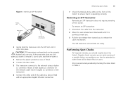
...2 Move the wire release lever downwards until it clicks into the duplex LC connector on users. 3Com recommends periodically checking the items listed in Table 6. The SFP transceiver should visually check the Switch. Removing an SFP Transceiver Removing an SFP transceiver does not require powering off the... Gigabit Ethernet connection. Figure 4 Inserting an SFP Transceiver Product label Wire release lever Module Present Suitable slot on the front of the Switch to ensure that it is pointing toward you. 3 Pull the wire release lever toward you to release the catch mechanism. CAUTION: ...
...2 Move the wire release lever downwards until it clicks into the duplex LC connector on users. 3Com recommends periodically checking the items listed in Table 6. The SFP transceiver should visually check the Switch. Removing an SFP Transceiver Removing an SFP transceiver does not require powering off the... Gigabit Ethernet connection. Figure 4 Inserting an SFP Transceiver Product label Wire release lever Module Present Suitable slot on the front of the Switch to ensure that it is pointing toward you. 3 Pull the wire release lever toward you to release the catch mechanism. CAUTION: ...
User Guide
Page 20
20 CHAPTER 2: INSTALLING THE SWITCH Table 6 Items to Check Item Verify That Cabling All external cabling connections are secure and that no cables are pulled taut Cooling Fan Where possible, check that the cooling fan is fitted on page 49. If you experience any problems operating the Switch, refer to the unit. The fan is operating by listening to "Troubleshooting" on the right side of the unit (when viewed from the front).
20 CHAPTER 2: INSTALLING THE SWITCH Table 6 Items to Check Item Verify That Cabling All external cabling connections are secure and that no cables are pulled taut Cooling Fan Where possible, check that the cooling fan is fitted on page 49. If you experience any problems operating the Switch, refer to the unit. The fan is operating by listening to "Troubleshooting" on the right side of the unit (when viewed from the front).
User Guide
Page 21
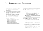
...application, which is included on the Web interface. The following : 1 On a computer that has a Web browser Running the Discovery Application The 3Com Baseline Switch 2816-SFP/2824-SFP Plus CD-ROM contains, among others, the Discovery application. It also introduces the menu items and buttons that are covered: &#...discovery.exe. If it does not start automatically. If you only want the Switch to function as a basic layer 2 switch, you need to the Web interface, you do the following topics are available on 3Com Baseline Switch 2816-SFP/2824-SFP Plus CD-ROM that is supplied with your...
...application, which is included on the Web interface. The following : 1 On a computer that has a Web browser Running the Discovery Application The 3Com Baseline Switch 2816-SFP/2824-SFP Plus CD-ROM contains, among others, the Discovery application. It also introduces the menu items and buttons that are covered: &#...discovery.exe. If it does not start automatically. If you only want the Switch to function as a basic layer 2 switch, you need to the Web interface, you do the following topics are available on 3Com Baseline Switch 2816-SFP/2824-SFP Plus CD-ROM that is supplied with your...

User Guide
Page 22
... page that connects the computer to the Switch, and then click Next. Discovery searches the network for 3Com devices. The Completing the 3Com Discovery Application screen appears. 4 Click Finish.... 22 CHAPTER 3: CONNECTING TO THE WEB INTERFACE The Welcome screen of Discovery Figure 6 Discovered Devices Screen 2 If the computer has multiple network adapters, select the adapter that appears is complete, the Discovered Devices screen displays detected network devices. 3 On the Discovered Devices screen, click Baseline Switch 2816...
... page that connects the computer to the Switch, and then click Next. Discovery searches the network for 3Com devices. The Completing the 3Com Discovery Application screen appears. 4 Click Finish.... 22 CHAPTER 3: CONNECTING TO THE WEB INTERFACE The Welcome screen of Discovery Figure 6 Discovered Devices Screen 2 If the computer has multiple network adapters, select the adapter that appears is complete, the Discovered Devices screen displays detected network devices. 3 On the Discovered Devices screen, click Baseline Switch 2816...