
User Guide
Page 1
Baseline Switch 2226-SFP Plus Baseline Switch 2426-PWR Plus Baseline Switch 2250-SFP Plus Installation and User Guide Installations- und Bedienungsanleitung 3CBLSF26 3CBLSF26PWR 3CBLSF50 www.3Com.com Part No. 10016622 Published May 2008
Baseline Switch 2226-SFP Plus Baseline Switch 2426-PWR Plus Baseline Switch 2250-SFP Plus Installation and User Guide Installations- und Bedienungsanleitung 3CBLSF26 3CBLSF26PWR 3CBLSF50 www.3Com.com Part No. 10016622 Published May 2008
User Guide
Page 3
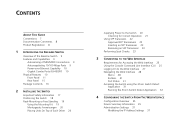
CONTENTS ABOUT THIS GUIDE Conventions 7 Documentation Comments 8 Product Registration 8 1 INTRODUCING THE BASELINE SWITCH Overview of the Baseline Switch 9 Features and Capabilities 9 Autosensing of MDI/MDIX Connections 9 Autonegotiating 10/100 Mbps Ports 9 Power-over-Ethernet ... Navigating the Web Interface 28 Menu 28 Buttons 31 Port Status 31 Accessing the Switch using the 3Com Switch Detect Application 31 Running the 3Com Switch Detect Application 32 4 CONFIGURING THE SWITCH FROM THE WEB INTERFACE Configuration Overview 35 Device Summary Information 35 Administration Settings 37 ...
CONTENTS ABOUT THIS GUIDE Conventions 7 Documentation Comments 8 Product Registration 8 1 INTRODUCING THE BASELINE SWITCH Overview of the Baseline Switch 9 Features and Capabilities 9 Autosensing of MDI/MDIX Connections 9 Autonegotiating 10/100 Mbps Ports 9 Power-over-Ethernet ... Navigating the Web Interface 28 Menu 28 Buttons 31 Port Status 31 Accessing the Switch using the 3Com Switch Detect Application 31 Running the 3Com Switch Detect Application 32 4 CONFIGURING THE SWITCH FROM THE WEB INTERFACE Configuration Overview 35 Device Summary Information 35 Administration Settings 37 ...
User Guide
Page 7
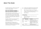
...-SFP Plus (3CBLSF26) Baseline Switch 2426-PWR Plus (3CBLSF26PWR) Baseline Switch 2250-SFP Plus (3CBLSF50) Unless noted otherwise, the features, specifications and procedures described hereafter are used throughout this guide. If release notes are provided for installing and setting up network equipment; Most user guides and release notes are based on the 3Com World Wide Web site...
...-SFP Plus (3CBLSF26) Baseline Switch 2426-PWR Plus (3CBLSF26PWR) Baseline Switch 2250-SFP Plus (3CBLSF50) Unless noted otherwise, the features, specifications and procedures described hereafter are used throughout this guide. If release notes are provided for installing and setting up network equipment; Most user guides and release notes are based on the 3Com World Wide Web site...
User Guide
Page 8
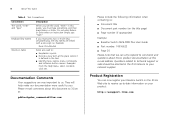
...-PWR Plus User Guide ■ Part number: 10016622 ■ Page 25 Please note that we can now register your Baseline Switch on the 3Com Web site to receive up-to-date information on your network supplier. Example: Press Ctrl+Alt+Del Italics are used to you. Please e-mail comments ...about this document to 3Com at this guide, you must press two or more useful to : ■ Emphasize a point. ■ Denote a new term at the place where it is defined...
...-PWR Plus User Guide ■ Part number: 10016622 ■ Page 25 Please note that we can now register your Baseline Switch on the 3Com Web site to receive up-to-date information on your network supplier. Example: Press Ctrl+Alt+Del Italics are used to you. Please e-mail comments ...about this document to 3Com at this guide, you must press two or more useful to : ■ Emphasize a point. ■ Denote a new term at the place where it is defined...
User Guide
Page 9
... shipped ready for users who want the high-speed performance of 10/100 switching with the added functionality of the 3Com Baseline Switch 2226-SFP Plus, 3Com Baseline Switch 2426-PWR Plus, and 3Com Baseline Switch 2250-SFP Plus. This allows you get to another switch port, server, or workstation without additional configuration. Overview of MDI/MDIX Connections All ports on the...
... shipped ready for users who want the high-speed performance of 10/100 switching with the added functionality of the 3Com Baseline Switch 2226-SFP Plus, 3Com Baseline Switch 2426-PWR Plus, and 3Com Baseline Switch 2250-SFP Plus. This allows you get to another switch port, server, or workstation without additional configuration. Overview of MDI/MDIX Connections All ports on the...
User Guide
Page 10
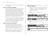
... connections can operate in either half-duplex or full-duplex mode. The numbers in these diagrams refer to a port can directly draw power from the Switch over -Ethernet (PoE) standard. Physical Features Figures 1, 2, and 3 show the front and rear panels of 802.3at, delivering up to the maximum power budget available... availability. Any 802.3af compliant device attached to numbered sections in "Front Panel" on page 11 and "Rear Panel" on page 15. 10 INTRODUCING THE BASELINE SWITCH 10/100 Mbps ports can only operate in full duplex mode.
... connections can operate in either half-duplex or full-duplex mode. The numbers in these diagrams refer to a port can directly draw power from the Switch over -Ethernet (PoE) standard. Physical Features Figures 1, 2, and 3 show the front and rear panels of 802.3at, delivering up to the maximum power budget available... availability. Any 802.3af compliant device attached to numbered sections in "Front Panel" on page 11 and "Rear Panel" on page 15. 10 INTRODUCING THE BASELINE SWITCH 10/100 Mbps ports can only operate in full duplex mode.
User Guide
Page 11
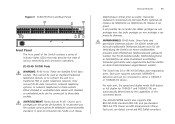
...223;e, Telefonnetzsysteme or Netztelefone an diese Steckdosen anschließen. Diese Porte sind geschützte Datensteckdosen. Figure 3 3CBLSF50 Front and Rear Panels Front Panel The front panel of the Switch contains a series of indicator lights (LEDs) that help describe the state of the connected device. These are ...;seaux de téléphonie ou téléphones de réseaux à ces prises. The Switch has 24 or 48 10/100 Mbps auto-negotiating ports. The 3CBLSF26PWR Switch also supports IEEE 802.3af-2003 standard (802.3af) and pre-standard P802.3at DTE Power via MDI ...
...223;e, Telefonnetzsysteme or Netztelefone an diese Steckdosen anschließen. Diese Porte sind geschützte Datensteckdosen. Figure 3 3CBLSF50 Front and Rear Panels Front Panel The front panel of the Switch contains a series of indicator lights (LEDs) that help describe the state of the connected device. These are ...;seaux de téléphonie ou téléphones de réseaux à ces prises. The Switch has 24 or 48 10/100 Mbps auto-negotiating ports. The 3CBLSF26PWR Switch also supports IEEE 802.3af-2003 standard (802.3af) and pre-standard P802.3at DTE Power via MDI ...
User Guide
Page 12
...the required DC power, up to a maximum of 29.6 W measured at the PD, assuming 100 m Cat 5E cable connected between the Switch and remote 1000 Mbps workgroups or to create a high-capacity aggregated link backbone connection. The SFP port supports full duplex mode only. To.... If the link connection on 3CBLSF50. The corresponding 10/100/1000 port is disabled when an SFP link connection is assigned to the Switch, set the admin password, reboot the Switch, or upgrade the Switch firmware via the Web interface. 12 INTRODUCING THE BASELINE SWITCH network devices, such as follows:...
...the required DC power, up to a maximum of 29.6 W measured at the PD, assuming 100 m Cat 5E cable connected between the Switch and remote 1000 Mbps workgroups or to create a high-capacity aggregated link backbone connection. The SFP port supports full duplex mode only. To.... If the link connection on 3CBLSF50. The corresponding 10/100/1000 port is disabled when an SFP link connection is assigned to the Switch, set the admin password, reboot the Switch, or upgrade the Switch firmware via the Web interface. 12 INTRODUCING THE BASELINE SWITCH network devices, such as follows:...
User Guide
Page 14
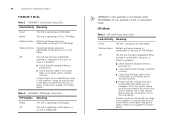
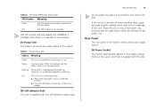
14 INTRODUCING THE BASELINE SWITCH 1000BASE-T Mode Table 3 1000BASE-T Link/Activity Status LEDs Link/Activity Meaning Green The link is inserted correctly. ■ Ensure that the transmit (TX) and receive (...
14 INTRODUCING THE BASELINE SWITCH 1000BASE-T Mode Table 3 1000BASE-T Link/Activity Status LEDs Link/Activity Meaning Green The link is inserted correctly. ■ Ensure that the transmit (TX) and receive (...
User Guide
Page 15
...The SFP module will only disable the 1000BASE-T interface once there is in fail-safe mode. Yellow Internal power, POST, or loopback test has failed. Switch is a valid link on and ready for use the power cord that the pads locate within the recesses of the link status. Flashing The...-adhesive rubber pads. Physical Features 15 Do not apply the pads if you intend to the supply voltage. Rear Panel The rear panel of the Switch. Only use . Off The SFP module is inserted, regardless of the lower unit. Table 6 SFP Mode SFP/Duplex Status LEDs SFP/Duplex Meaning Green ...
...The SFP module will only disable the 1000BASE-T interface once there is in fail-safe mode. Yellow Internal power, POST, or loopback test has failed. Switch is a valid link on and ready for use the power cord that the pads locate within the recesses of the link status. Flashing The...-adhesive rubber pads. Physical Features 15 Do not apply the pads if you intend to the supply voltage. Rear Panel The rear panel of the Switch. Only use . Off The SFP module is inserted, regardless of the lower unit. Table 6 SFP Mode SFP/Duplex Status LEDs SFP/Duplex Meaning Green ...
User Guide
Page 16
The Switch comes with: ■ One power cord ■ One console cable ■ Four standard height, self-adhesive rubber pads ■ One mounting kit (part number 123193-104) ■ Installation CD ■ This User Guide ■ Warranty flyer The Switch is complete. 16 INTRODUCING THE BASELINE SWITCH Package Contents Before installing and using the Switch, verify that your 3Com network supplier immediately. If any of the above items are damaged or missing, contact your Switch package is powered from the AC supply.
The Switch comes with: ■ One power cord ■ One console cable ■ Four standard height, self-adhesive rubber pads ■ One mounting kit (part number 123193-104) ■ Installation CD ■ This User Guide ■ Warranty flyer The Switch is complete. 16 INTRODUCING THE BASELINE SWITCH Package Contents Before installing and using the Switch, verify that your 3Com network supplier immediately. If any of the above items are damaged or missing, contact your Switch package is powered from the AC supply.
User Guide
Page 17
... contains information that was included with this would be: Informações de Segurança e Regulatórias da Famila de Switches 3Com) incluido no produto. You can find the 3Com Switch Family Safety and Regulatory Information manual on the product CD-ROM that you need to the safety information found in der...
... contains information that was included with this would be: Informações de Segurança e Regulatórias da Famila de Switches 3Com) incluido no produto. You can find the 3Com Switch Family Safety and Regulatory Information manual on the product CD-ROM that you need to the safety information found in der...
User Guide
Page 18
... can be exceeded. Istnieje także możliwość pobrania instrukcji bezpośrednio ze strony internetowej www.3Com.com Positioning the Switch The Switch is as free from dust as possible. ■ Temperature operating limits are not likely to be free-standing or mounted ...", che troverete incluso a questo prodotto. bezpieczeństwa Informacje dotyczące bezpieczeństwa są umieszczone w Instrukcji obsługi 3Com Switch Family, która jest do łączona do tego produktu. A mounting kit, containing two mounting brackets and four screws, is...
... can be exceeded. Istnieje także możliwość pobrania instrukcji bezpośrednio ze strony internetowej www.3Com.com Positioning the Switch The Switch is as free from dust as possible. ■ Temperature operating limits are not likely to be free-standing or mounted ...", che troverete incluso a questo prodotto. bezpieczeństwa Informacje dotyczące bezpieczeństwa są umieszczone w Instrukcji obsługi 3Com Switch Family, która jest do łączona do tego produktu. A mounting kit, containing two mounting brackets and four screws, is...
User Guide
Page 19
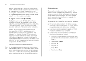
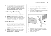
... self-adhesive pads from the unit before continuing. Figure 4 Rack Mounting the Unit 4 Repeat steps 2 and 3 for rack mounting the unit. The Switch is not available, try to a ground point. CAUTION: Disconnect all cables from the underside of more than six units. Rack-Mounting or Free-Standing ...hard, flat surface with the front facing towards you should take note of the guidelines given in your equipment. If one side of different size Baseline or Superstack 3 units, the smaller units must be mounted in a 19-inch equipment rack using the mounting kit, or it can cause ...
... self-adhesive pads from the unit before continuing. Figure 4 Rack Mounting the Unit 4 Repeat steps 2 and 3 for rack mounting the unit. The Switch is not available, try to a ground point. CAUTION: Disconnect all cables from the underside of more than six units. Rack-Mounting or Free-Standing ...hard, flat surface with the front facing towards you should take note of the guidelines given in your equipment. If one side of different size Baseline or Superstack 3 units, the smaller units must be mounted in a 19-inch equipment rack using the mounting kit, or it can cause ...
User Guide
Page 21
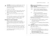
...on and ready to its factory defaults erases all your 3Com network supplier for a solution. CAUTION: Resetting the Switch to use. You will need to power on the Switch again ■ If the Switch still does not operate, contact your 3Com network supplier If POST fails, try powering on and ... light up . If these do not resolve the issue: ■ Check the 3Com Knowledgebase for assistance. To power on the Switch: 1 Plug the power cord into a power outlet. The only way to reconfigure the Switch after POST. Off The unit is not receiving power: ■ Verify that POST...
...on and ready to its factory defaults erases all your 3Com network supplier for a solution. CAUTION: Resetting the Switch to use. You will need to power on the Switch again ■ If the Switch still does not operate, contact your 3Com network supplier If POST fails, try powering on and ... light up . If these do not resolve the issue: ■ Check the 3Com Knowledgebase for assistance. To power on the Switch: 1 Plug the power cord into a power outlet. The only way to reconfigure the Switch after POST. Off The unit is not receiving power: ■ Verify that POST...
User Guide
Page 22
... slot. If the SFP transceiver is not supported, the Switch will not operate within the Switch. See "Troubleshooting" on the 3Com Web site, enter this transceiver to connect the Switch directly to a single mode fiber-optic cable or to multimode fiber using 3Com SFPs in the Switch. Ensure the wire release lever is correct at the...
... slot. If the SFP transceiver is not supported, the Switch will not operate within the Switch. See "Troubleshooting" on the 3Com Web site, enter this transceiver to connect the Switch directly to a single mode fiber-optic cable or to multimode fiber using 3Com SFPs in the Switch. Ensure the wire release lever is correct at the...
User Guide
Page 23
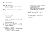
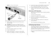
... until it clicks into place. If the transceiver does not click when you should slide out easily. The SFP transceiver should visually check the Switch. Performing Spot Checks At frequent intervals, you insert it, remove it, turn it over, and reinsert it. 3 Remove the plastic protective...fitted. 4 Connect the fiber cable. 5 Attach a male duplex LC connector on the network cable into the duplex LC connector on users. 3Com recommends periodically checking the items listed in Table 9. any problems can be least effect on the transceiver. Figure 5 Inserting an SFP Transceiver 2 ...
... until it clicks into place. If the transceiver does not click when you should slide out easily. The SFP transceiver should visually check the Switch. Performing Spot Checks At frequent intervals, you insert it, remove it, turn it over, and reinsert it. 3 Remove the plastic protective...fitted. 4 Connect the fiber cable. 5 Attach a male duplex LC connector on the network cable into the duplex LC connector on users. 3Com recommends periodically checking the items listed in Table 9. any problems can be least effect on the transceiver. Figure 5 Inserting an SFP Transceiver 2 ...
User Guide
Page 24
24 INSTALLING THE SWITCH Table 9 Items to Check Cabling Check that all external cabling connections are pulled taut. If you experience any problems operating the Switch, refer to the unit. Cooling fan (3CBLSF26PWR only) Where possible, check that no cables are secure and that the cooling fan is fitted near to the front right hand side of the unit (when viewed from the front). The fan is operating by listening to "Troubleshooting" on page 75.
24 INSTALLING THE SWITCH Table 9 Items to Check Cabling Check that all external cabling connections are pulled taut. If you experience any problems operating the Switch, refer to the unit. Cooling fan (3CBLSF26PWR only) Where possible, check that no cables are secure and that the cooling fan is fitted near to the front right hand side of the unit (when viewed from the front). The fan is operating by listening to "Troubleshooting" on page 75.

User Guide
Page 25
... Web interface of the following topics are available on the CD-ROM that was supplied with your Switch. ■ The 3Com Switch Detect application, that is connected to the Web interface using the 3Com Switch Detect Application The Switch support the following browsers: ■ Microsoft Internet Explorer (V6.0 and subsequent releases) ■ Mozilla Firefox (V2.0 and...
... Web interface of the following topics are available on the CD-ROM that was supplied with your Switch. ■ The 3Com Switch Detect application, that is connected to the Web interface using the 3Com Switch Detect Application The Switch support the following browsers: ■ Microsoft Internet Explorer (V6.0 and subsequent releases) ■ Mozilla Firefox (V2.0 and...
User Guide
Page 26
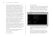
... is not suitable, you see the IP address that shown in a prompt on your keyboard will now be connected to the top cover of the Switch. If there is no password. In order to see information similar to obtain an IP address. The CLI Command Reference Guide is necessary to use... in Figure 6. Enter summary to obtain an IP address from the last two numbers of 169.254.xx.yy. Included in this period if the Switch has not been able to obtain an IP address, will take up sequence and is available). Only after the prompts. If the 169.254.xx...
... is not suitable, you see the IP address that shown in a prompt on your keyboard will now be connected to the top cover of the Switch. If there is no password. In order to see information similar to obtain an IP address. The CLI Command Reference Guide is necessary to use... in Figure 6. Enter summary to obtain an IP address from the last two numbers of 169.254.xx.yy. Included in this period if the Switch has not been able to obtain an IP address, will take up sequence and is available). Only after the prompts. If the 169.254.xx...


