
User Manual
Page 3
... 1 INTRODUCING THE BASELINE SWITCH Overview of the Baseline Switch 7 Features and Capabilities 7 Autosensing of MDI/MDIX Connections 7 Autonegotiating 10/100/1000 Mbps Ports 7 SFP Ports 7 Physical Features 8 Front Panel 8 Rear Panel 11 Package Contents 11 2 INSTALLING THE SWITCH Before You Begin 13 Positioning the Switch 13 Rack-Mounting or...14 Using the Mounting Kit 14 Montagesatz Anweisungen 15 Placing Units On Top of Each Other 15 Supplying Power to the Switch 16 Checking for Correct Operation 16 Connecting a Network Device 17 Using SFP Transceivers 18 Approved SFP Transceivers 18 Inserting ...
... 1 INTRODUCING THE BASELINE SWITCH Overview of the Baseline Switch 7 Features and Capabilities 7 Autosensing of MDI/MDIX Connections 7 Autonegotiating 10/100/1000 Mbps Ports 7 SFP Ports 7 Physical Features 8 Front Panel 8 Rear Panel 11 Package Contents 11 2 INSTALLING THE SWITCH Before You Begin 13 Positioning the Switch 13 Rack-Mounting or...14 Using the Mounting Kit 14 Montagesatz Anweisungen 15 Placing Units On Top of Each Other 15 Supplying Power to the Switch 16 Checking for Correct Operation 16 Connecting a Network Device 17 Using SFP Transceivers 18 Approved SFP Transceivers 18 Inserting ...

User Manual
Page 5
... Throughout this guide. Conventions Table 1 and Table 2 list conventions that are linked with this 3Com Baseline Switch 2816-SFP/2824-SFP Plus and contains information that alerts you to as the Switch. Keyboard key names If you must type something, and then press Return or Enter. Example:...enter" and "type" When you must press two or more keys simultaneously, the key names are used throughout this guide, the 3Com Baseline Switch 2816/2824-SFP Plus is referred to as Twisted Pair Cables throughout this guide, you see the word "enter" in the release note. ...
... Throughout this guide. Conventions Table 1 and Table 2 list conventions that are linked with this 3Com Baseline Switch 2816-SFP/2824-SFP Plus and contains information that alerts you to as the Switch. Keyboard key names If you must type something, and then press Return or Enter. Example:...enter" and "type" When you must press two or more keys simultaneously, the key names are used throughout this guide, the 3Com Baseline Switch 2816/2824-SFP Plus is referred to as Twisted Pair Cables throughout this guide, you see the word "enter" in the release note. ...

User Manual
Page 6
...title page) ■ Page number (if appropriate) Example: ■ 3Com Baseline Switch 2816-SFP/2824-SFP Plus User Guide ■ Part Number DUA1648-5AAA03 ■ Page 24 Do not use this guide, each 3Com Baseline Switch 2816-SFP/2824-SFP Plus documentation set includes the following: ■ Online Help - ...Product Registration You can now register your Baseline Switch on the 3Com Web site to receive up-to-date information on your supplier...
...title page) ■ Page number (if appropriate) Example: ■ 3Com Baseline Switch 2816-SFP/2824-SFP Plus User Guide ■ Part Number DUA1648-5AAA03 ■ Page 24 Do not use this guide, each 3Com Baseline Switch 2816-SFP/2824-SFP Plus documentation set includes the following: ■ Online Help - ...Product Registration You can now register your Baseline Switch on the 3Com Web site to receive up-to-date information on your supplier...

User Manual
Page 7
... (SFP) transceiver slots on the other hand, only operate in Overview of the Baseline Switch The 3Com Baseline Switch 2816-SFP/2824-SFP Plus is shipped ready for users who want the high-speed performance of 10/100/1000 switching with the added functionality of the device. This allows you get to each port ... 10/100/1000 Mbps Ports Each 10/100/1000 Mbps port automatically determines the speed and duplex mode of the 3Com® Baseline Switch 2816/2824-SFP Plus. SFP Ports The four SFP ports support fiber Gigabit Ethernet short-wave (SX) and long-wave (LX) SFP transceivers in full ...
... (SFP) transceiver slots on the other hand, only operate in Overview of the Baseline Switch The 3Com Baseline Switch 2816-SFP/2824-SFP Plus is shipped ready for users who want the high-speed performance of 10/100/1000 switching with the added functionality of the device. This allows you get to each port ... 10/100/1000 Mbps Ports Each 10/100/1000 Mbps port automatically determines the speed and duplex mode of the 3Com® Baseline Switch 2816/2824-SFP Plus. SFP Ports The four SFP ports support fiber Gigabit Ethernet short-wave (SX) and long-wave (LX) SFP transceivers in full ...

User Manual
Page 8
...;gés par des prises de données. This offers you the flexibility of the Switch. They cannot be connected to a traditional PBX or public telephone network. Figure 1 Front and Rear Panels (2816-SFP) 1 1 9 8 4 5 12 13 Baseline Switch 2816-SFP Plus Module Present 8 16 Link/Activity : Green = 1000M, Yellow = 10... wie normale traditionelle Telefonsteckdosen noch für die Verbindung der Einheit mit einem traditionellem privatem oder öffentlichem Telefonnetzwerk gebraucht werden. The Switch has 16 (2816-SFP) or 24 (2824-SFP) 10/100/1000 Mbps auto-negotiating ports.
...;gés par des prises de données. This offers you the flexibility of the Switch. They cannot be connected to a traditional PBX or public telephone network. Figure 1 Front and Rear Panels (2816-SFP) 1 1 9 8 4 5 12 13 Baseline Switch 2816-SFP Plus Module Present 8 16 Link/Activity : Green = 1000M, Yellow = 10... wie normale traditionelle Telefonsteckdosen noch für die Verbindung der Einheit mit einem traditionellem privatem oder öffentlichem Telefonnetzwerk gebraucht werden. The Switch has 16 (2816-SFP) or 24 (2824-SFP) 10/100/1000 Mbps auto-negotiating ports.
User Manual
Page 9
In such a configuration, you may notice some degradation of network performance. 3Com recommends that you use devices that are capable of auto-negotiation (and that you the flexibility of the same number. CAUTION: The Switch supports full duplex auto-negotiation. If an SFP transceiver (purchased separately) is... 21 to a 10BASE-T, 100BASE-TX, or a 1000BASE-T device. supports automatic MDI/MDI-X detection and can be connected to 24 (2824-SFP) on the Switch. SFP ports are being received or transmitted on the Yellow port at 10 or 100 Mbps. Table 1 10BASE-T/100BASE-TX Ports Status ...
In such a configuration, you may notice some degradation of network performance. 3Com recommends that you use devices that are capable of auto-negotiation (and that you the flexibility of the same number. CAUTION: The Switch supports full duplex auto-negotiation. If an SFP transceiver (purchased separately) is... 21 to a 10BASE-T, 100BASE-TX, or a 1000BASE-T device. supports automatic MDI/MDI-X detection and can be connected to 24 (2824-SFP) on the Switch. SFP ports are being received or transmitted on the Yellow port at 10 or 100 Mbps. Table 1 10BASE-T/100BASE-TX Ports Status ...

User Manual
Page 10
...half-duplex mode. Table 2 Module Active LEDs Status Meaning Green Fiber SFP is faulty. If these checks do not identify the cause of the Switch: Table 4 Power LEDs Status Meaning Green The unit is operating in the slot. (5) Port Duplex LEDs The second and fourth (bottom) ... the duplex status of any SFP modules that are not swapped. Yellow The port is operating in failsafe mode. 10 CHAPTER 1: INTRODUCING THE BASELINE SWITCH Table 1 10BASE-T/100BASE-TX Ports Flashing Port disabled or link loopback error. Table 3 Duplex LEDs Status Meaning Off No link, not yet ...
...half-duplex mode. Table 2 Module Active LEDs Status Meaning Green Fiber SFP is faulty. If these checks do not identify the cause of the Switch: Table 4 Power LEDs Status Meaning Green The unit is operating in the slot. (5) Port Duplex LEDs The second and fourth (bottom) ... the duplex status of any SFP modules that are not swapped. Yellow The port is operating in failsafe mode. 10 CHAPTER 1: INTRODUCING THE BASELINE SWITCH Table 1 10BASE-T/100BASE-TX Ports Flashing Port disabled or link loopback error. Table 3 Duplex LEDs Status Meaning Off No link, not yet ...

User Manual
Page 11
CAUTION: 3Com recommends that the pads locate with the unit. (9) Recovery button The recovery button reinitializes the Switch. Place the unit on top of the lower unit, ensuring that you back up your configuration settings before you recover the Switch, otherwise your Switch package is complete. Only use the power cord... The unit is supplied with : ■ One power cord ■ Four standard height, self-adhesive rubber pads ■ One mounting kit ■ 3Com Installation CD ■ This User Guide ■ Warranty flyer If any of the above items are damaged or missing, contact your...
CAUTION: 3Com recommends that the pads locate with the unit. (9) Recovery button The recovery button reinitializes the Switch. Place the unit on top of the lower unit, ensuring that you back up your configuration settings before you recover the Switch, otherwise your Switch package is complete. Only use the power cord... The unit is supplied with : ■ One power cord ■ Four standard height, self-adhesive rubber pads ■ One mounting kit ■ 3Com Installation CD ■ This User Guide ■ Warranty flyer If any of the above items are damaged or missing, contact your...

User Manual
Page 12
12 CHAPTER 1: INTRODUCING THE BASELINE SWITCH
12 CHAPTER 1: INTRODUCING THE BASELINE SWITCH

User Manual
Page 13
...ADVERTENCIA: Información de Seguridad. WARNHINWEIS: Sicherheitsinformationen. AVVERTENZA: Informazioni di Sicurezza. 2 INSTALLING THE SWITCH This chapter contains information that you need to the Switch ■ Connecting a Network Device ■ Using SFP Transceivers ■ Performing Spot Checks Before... della presente guida per l'utente. AVERTISSEMENT: Consignes de Sécurité. Bevor Sie Komponenten aus dem Switch entfernen oder dem Switch hinzufuegen oder Instandhaltungsarbeiten verrichten, lesen Sie die Sicherheitsanweisungen, die in Anhang B (Appendix C) in Appendix C of...
...ADVERTENCIA: Información de Seguridad. WARNHINWEIS: Sicherheitsinformationen. AVVERTENZA: Informazioni di Sicurezza. 2 INSTALLING THE SWITCH This chapter contains information that you need to the Switch ■ Connecting a Network Device ■ Using SFP Transceivers ■ Performing Spot Checks Before... della presente guida per l'utente. AVERTISSEMENT: Consignes de Sécurité. Bevor Sie Komponenten aus dem Switch entfernen oder dem Switch hinzufuegen oder Instandhaltungsarbeiten verrichten, lesen Sie die Sicherheitsanweisungen, die in Anhang B (Appendix C) in Appendix C of...

User Manual
Page 14
... enter the case of the unit. ■ Air flow around the unit and through the vents in the side of different size Baseline or Superstack® 3 units, the smaller units must be free-standing. When mounting the unit, you should take note of electrical noise. The... from the unit. Static discharge can be rack-mounted in a wiring closet or equipment room. CAUTION: If installing the Switch in a free-standing stack of the case is not restricted (3Com recommends that you . 2 Locate a mounting bracket over the mounting holes on copper cabling and introduce errors, therefore slowing ...
... enter the case of the unit. ■ Air flow around the unit and through the vents in the side of different size Baseline or Superstack® 3 units, the smaller units must be free-standing. When mounting the unit, you should take note of electrical noise. The... from the unit. Static discharge can be rack-mounted in a wiring closet or equipment room. CAUTION: If installing the Switch in a free-standing stack of the case is not restricted (3Com recommends that you . 2 Locate a mounting bracket over the mounting holes on copper cabling and introduce errors, therefore slowing ...

User Manual
Page 16
... earth ground during normal use Ensure that the pads of the upper unit line up , refer to "(6) Power LED" on the front panel of the Switch flashes green. Refer to "(8) Power Supply" on page 11 for use . If the Power LED does not light up with the recesses of the lower... black outs, power dips and electrical storms. The unit is clean and free from lightning and power surges. We recommend that you power on the Switch, it means that the network cables and the power cable are securely connected. If the Power LED turns yellow after POST. CAUTION: The...
... earth ground during normal use Ensure that the pads of the upper unit line up , refer to "(6) Power LED" on the front panel of the Switch flashes green. Refer to "(8) Power Supply" on page 11 for use . If the Power LED does not light up with the recesses of the lower... black outs, power dips and electrical storms. The unit is clean and free from lightning and power surges. We recommend that you power on the Switch, it means that the network cables and the power cable are securely connected. If the Power LED turns yellow after POST. CAUTION: The...

User Manual
Page 17
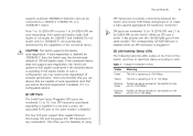
...3Com network supplier for a solution. For optimal connections, ensure that the power cord is not longer than 100 m (328 ft). The Switch is in fail-safe mode. This can happen if a ports or ports fail when the Switch was successfully completed. ■ Reset the Switch. Figure 3 Connecting Devices to the Switch Baseline 10/100 Switch Endstations on switched... 100 Mbps connections Baseline 10/100 Switch Endstations on switched 100 Mbps...
...3Com network supplier for a solution. For optimal connections, ensure that the power cord is not longer than 100 m (328 ft). The Switch is in fail-safe mode. This can happen if a ports or ports fail when the Switch was successfully completed. ■ Reset the Switch. Figure 3 Connecting Devices to the Switch Baseline 10/100 Switch Endstations on switched... 100 Mbps connections Baseline 10/100 Switch Endstations on switched 100 Mbps...

User Manual
Page 18
... operation, 3Com recommends using a conditioned launch cable. Use this transceiver to connect the Switch directly to a single-mode fiber-optic cable or to multimode fiber using Category 5e or 6 cables. Inserting an SFP Transceiver To be one of approved SFP transceivers for the Switch on the Switch. Approved... it . SFP transceivers are hot-insertable and hot-swappable. You can remove them into your Internet browser: www.3com.com 3Com recommends using 3Com SFPs on the 3Com Corporation World Wide Web site, enter this URL into any SFP port without having to power off the...
... operation, 3Com recommends using a conditioned launch cable. Use this transceiver to connect the Switch directly to a single-mode fiber-optic cable or to multimode fiber using Category 5e or 6 cables. Inserting an SFP Transceiver To be one of approved SFP transceivers for the Switch on the Switch. Approved... it . SFP transceivers are hot-insertable and hot-swappable. You can remove them into your Internet browser: www.3com.com 3Com recommends using 3Com SFPs on the 3Com Corporation World Wide Web site, enter this URL into any SFP port without having to power off the...

User Manual
Page 19
...cable. 5 The transceiver connects to release the catch mechanism. Removing an SFP Transceiver Removing an SFP transceiver does not require powering off the Switch. Performing Spot Checks 19 7 Check the Module Active LEDs on the transceiver. 6 Connect the other end of a possible failure; CAUTION... the transceiver. 2 Move the wire release lever downwards until it clicks into place. any problems can be least effect on users. 3Com recommends periodically checking the items listed in Table 6. If the transceiver does not click when you should slide out easily. Regular checks ...
...cable. 5 The transceiver connects to release the catch mechanism. Removing an SFP Transceiver Removing an SFP transceiver does not require powering off the Switch. Performing Spot Checks 19 7 Check the Module Active LEDs on the transceiver. 6 Connect the other end of a possible failure; CAUTION... the transceiver. 2 Move the wire release lever downwards until it clicks into place. any problems can be least effect on users. 3Com recommends periodically checking the items listed in Table 6. If the transceiver does not click when you should slide out easily. Regular checks ...

User Manual
Page 20
The fan is operating by listening to "Troubleshooting" on the right side of the unit (when viewed from the front). 20 CHAPTER 2: INSTALLING THE SWITCH Table 6 Items to Check Item Verify That Cabling All external cabling connections are secure and that no cables are pulled taut Cooling Fan Where possible, check that the cooling fan is fitted on page 49. If you experience any problems operating the Switch, refer to the unit.
The fan is operating by listening to "Troubleshooting" on the right side of the unit (when viewed from the front). 20 CHAPTER 2: INSTALLING THE SWITCH Table 6 Items to Check Item Verify That Cabling All external cabling connections are secure and that no cables are pulled taut Cooling Fan Where possible, check that the cooling fan is fitted on page 49. If you experience any problems operating the Switch, refer to the unit.
User Manual
Page 21
... the Web Interface To connect to the Web interface, you need to the \Discovery folder on 3Com Baseline Switch 2816-SFP/2824-SFP Plus CD-ROM that is supplied with your Switch ■ A computer that is connected to the Switch, insert the CD-ROM into its advanced settings. If it does not start automatically. The following...
... the Web Interface To connect to the Web interface, you need to the \Discovery folder on 3Com Baseline Switch 2816-SFP/2824-SFP Plus CD-ROM that is supplied with your Switch ■ A computer that is connected to the Switch, insert the CD-ROM into its advanced settings. If it does not start automatically. The following...
User Manual
Page 22
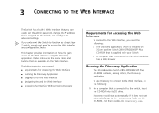
On this page, you need to enter the administration user name and password to gain access to the Switch, and then click Next. The Completing the 3Com Discovery Application screen appears. 4 Click Finish. Logging On to the Web Interface After the Web interface loads in ... Devices screen displays detected network devices. 3 On the Discovered Devices screen, click Baseline Switch 2816-SFP/2824-SFP Plus, and then click Next. When detection is the logon page. Discovery searches the network for 3Com devices. Figure 5 Welcome Screen of Discovery appears. The Web interface loads in ...
On this page, you need to enter the administration user name and password to gain access to the Switch, and then click Next. The Completing the 3Com Discovery Application screen appears. 4 Click Finish. Logging On to the Web Interface After the Web interface loads in ... Devices screen displays detected network devices. 3 On the Discovered Devices screen, click Baseline Switch 2816-SFP/2824-SFP Plus, and then click Next. When detection is the logon page. Discovery searches the network for 3Com devices. Figure 5 Welcome Screen of Discovery appears. The Web interface loads in ...

User Manual
Page 23
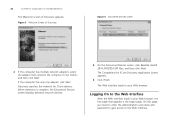
... is currently using. Figure 8 Web Interface Layout Main Section Buttons To log on the menu. The logon page also displays the IP address that the Switch is located on the menu, the related information appears in the main section of the Web interface. Menu Device Mimic Table 7 lists the available items...
... is currently using. Figure 8 Web Interface Layout Main Section Buttons To log on the menu. The logon page also displays the IP address that the Switch is located on the menu, the related information appears in the main section of the Web interface. Menu Device Mimic Table 7 lists the available items...

User Manual
Page 24
... detect and resolve cable issues System Tools Allows you to perform various system maintenance tasks, such as upgrading the firmware, resetting the Switch, backing up and maintain trunk membership for the page that is currently displayed. Traffic Prioritization Allows you will also need a network ...configure a port, click the port on each page is an image of the Switch's front panel, which indicates ports that you have made ■ Cancel - Menu Item Support Log Out Description Displays 3Com contact information and describes how to the port ■ Enable or disable the port...
... detect and resolve cable issues System Tools Allows you to perform various system maintenance tasks, such as upgrading the firmware, resetting the Switch, backing up and maintain trunk membership for the page that is currently displayed. Traffic Prioritization Allows you will also need a network ...configure a port, click the port on each page is an image of the Switch's front panel, which indicates ports that you have made ■ Cancel - Menu Item Support Log Out Description Displays 3Com contact information and describes how to the port ■ Enable or disable the port...


