User Guide
Page 3
...BASELINE SWITCH Overview of the Baseline Switch 2226 Plus 7 Features and Capabilities 7 Autosensing of MDI/MDIX Connections 7 Autonegotiating 10/100 Mbps Ports 7 SFP Ports 8 Traffic Prioritization 8 Physical Features 9 Front Panel 9 Rear Panel 12 Package Contents 12 2 INSTALLING THE SWITCH Before You Begin 13 Positioning the Switch 13 Aufstellen des Switch... Using Discovery 24 DHCP Assigned IP Address 24 Manually Assigned (Static) IP Address 25 4 CONFIGURING THE SWITCH Configuration Overview 27 Viewing Status Information 27 Changing the Admin Password 28 Modifying the IP Address Settings 29 ...
...BASELINE SWITCH Overview of the Baseline Switch 2226 Plus 7 Features and Capabilities 7 Autosensing of MDI/MDIX Connections 7 Autonegotiating 10/100 Mbps Ports 7 SFP Ports 8 Traffic Prioritization 8 Physical Features 9 Front Panel 9 Rear Panel 12 Package Contents 12 2 INSTALLING THE SWITCH Before You Begin 13 Positioning the Switch 13 Aufstellen des Switch... Using Discovery 24 DHCP Assigned IP Address 24 Manually Assigned (Static) IP Address 25 4 CONFIGURING THE SWITCH Configuration Overview 27 Viewing Status Information 27 Changing the Admin Password 28 Modifying the IP Address Settings 29 ...
User Guide
Page 4
... Traffic Priority 40 IP Phone Prioritization 40 List of Detected Phones 41 Upgrading the Firmware 41 Downloading Firmware Updates 41 Installing the Firmware on the Switch 42 5 TROUBLESHOOTING Resetting to Factory Defaults 43 Forgotten Password 44 Forgotten Static IP Address 44 Solving LED Issues 44 Solving Corrupted Firmware 45 If the...
... Traffic Priority 40 IP Phone Prioritization 40 List of Detected Phones 41 Upgrading the Firmware 41 Downloading Firmware Updates 41 Installing the Firmware on the Switch 42 5 TROUBLESHOOTING Resetting to Factory Defaults 43 Forgotten Password 44 Forgotten Static IP Address 44 Solving LED Issues 44 Solving Corrupted Firmware 45 If the...

User Guide
Page 6
...important to us : ■ Document title ■ Document part number (on the title page) ■ Page number (if appropriate) Example: ■ 3Com Baseline Switch 2226 Plus User Guide ■ Part number: DUA16475B-SAAA01 ■ Page 25 Please note that helps you . Accessible from the Web interface, provides information that ...related to technical support or sales should be directed in the first instance to comments and questions about this guide, each 3Com Baseline Switch 2226 Plus documentation set includes the following information when contacting us . Please e-mail comments about...
...important to us : ■ Document title ■ Document part number (on the title page) ■ Page number (if appropriate) Example: ■ 3Com Baseline Switch 2226 Plus User Guide ■ Part number: DUA16475B-SAAA01 ■ Page 25 Please note that helps you . Accessible from the Web interface, provides information that ...related to technical support or sales should be directed in the first instance to comments and questions about this guide, each 3Com Baseline Switch 2226 Plus documentation set includes the following information when contacting us . Please e-mail comments about...
User Guide
Page 7
...cable or a 'crossover' TP cable. It is necessary, unless you want the high-speed performance of the Baseline Switch 2226 Plus The 3Com Baseline Switch 2226 Plus is shipped ready for use configurable Switch. While there are four physical Gigabit ports, only a maximum of the device. This allows you get to ... capabilities. Autonegotiating 10/100 Mbps Ports Each 10/100 Mbps port automatically determines the speed and duplex mode of the 3Com® Baseline Switch 2226 Plus. Any port can be used to connect to know the physical features of two can therefore be operational at ...
...cable or a 'crossover' TP cable. It is necessary, unless you want the high-speed performance of the Baseline Switch 2226 Plus The 3Com Baseline Switch 2226 Plus is shipped ready for use configurable Switch. While there are four physical Gigabit ports, only a maximum of the device. This allows you get to ... capabilities. Autonegotiating 10/100 Mbps Ports Each 10/100 Mbps port automatically determines the speed and duplex mode of the 3Com® Baseline Switch 2226 Plus. Any port can be used to connect to know the physical features of two can therefore be operational at ...

User Guide
Page 8
...a different queue from the phone is forwarded through the phone until the phone has finished its initialization, do not connect any combination. The Switch is configured to comply with 802.1p, VLAN tagged frames. It examines each of which relates to a particular type of traffic. The ...eight distinct levels of priority (0 to 7), each packet that it receives to determine if it is priority-encoded. 8 CHAPTER 1: INTRODUCING THE BASELINE SWITCH SFP Ports The two SFP ports support fiber Gigabit Ethernet short-wave (SX) and long-wave (LX) SFP transceivers in the hardware of the...
...a different queue from the phone is forwarded through the phone until the phone has finished its initialization, do not connect any combination. The Switch is configured to comply with 802.1p, VLAN tagged frames. It examines each of which relates to a particular type of traffic. The ...eight distinct levels of priority (0 to 7), each packet that it receives to determine if it is priority-encoded. 8 CHAPTER 1: INTRODUCING THE BASELINE SWITCH SFP Ports The two SFP ports support fiber Gigabit Ethernet short-wave (SX) and long-wave (LX) SFP transceivers in the hardware of the...

User Guide
Page 9
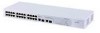
...Voice (interactive voice), less than 10 milliseconds latency and jitter 7 Network control reserved traffic The traffic prioritization feature supported by the Switch is compatible with shielded or unshielded jacks can be used as standard traditional telephone sockets, or to connect the unit to numbered...Front and Rear Panels 1 2 3 3C16475B 8 4 9 56 7 Front Panel The front panel of the Switch contains a series of indicator lights (LEDs) that help describe the state of the Switch. Raccorder seulement connecteurs de données RJ-45, systèmes de réseaux de tél&#...
...Voice (interactive voice), less than 10 milliseconds latency and jitter 7 Network control reserved traffic The traffic prioritization feature supported by the Switch is compatible with shielded or unshielded jacks can be used as standard traditional telephone sockets, or to connect the unit to numbered...Front and Rear Panels 1 2 3 3C16475B 8 4 9 56 7 Front Panel The front panel of the Switch contains a series of indicator lights (LEDs) that help describe the state of the Switch. Raccorder seulement connecteurs de données RJ-45, systèmes de réseaux de tél&#...

User Guide
Page 10
...the capabilities of any SFP modules that autonegotiation is enabled, if it is inserted in full-duplex mode). 10 CHAPTER 1: INTRODUCING THE BASELINE SWITCH werden. ADVERTENCIA: Puertos RJ-45. Conecte sólo conectores de datos RJ-45, sistemas de telefonía de red local o...;e, Telefonnetzsysteme or Netztelefone an diese Steckdosen anschließen. In such a configuration, you may notice some degradation of network performance. 3Com recommends that you use devices that are capable of autonegotiation (and that you ensure that are being received or transmitted on page 43...
...the capabilities of any SFP modules that autonegotiation is enabled, if it is inserted in full-duplex mode). 10 CHAPTER 1: INTRODUCING THE BASELINE SWITCH werden. ADVERTENCIA: Puertos RJ-45. Conecte sólo conectores de datos RJ-45, sistemas de telefonía de red local o...;e, Telefonnetzsysteme or Netztelefone an diese Steckdosen anschließen. In such a configuration, you may notice some degradation of network performance. 3Com recommends that you use devices that are capable of autonegotiation (and that you ensure that are being received or transmitted on page 43...

User Guide
Page 11
...the cause of the problem, it has priority over the 10/100/1000 port of the same number. Contact your 3Com network supplier ■ Power-on self-test is faulty. Switch is active, it may be that the power cord is connected cor- The 1000BASE-T RJ-45 ports support automatic...using SFP transceivers to provide connectivity between the Switch and remote 1000 Mbps workgroups or to other switches or hubs. When an SFP port is in progress ■ Power-on the Switch. rectly ■ If the unit still does not operate, contact your 3Com network supplier for all network connections to ...
...the cause of the problem, it has priority over the 10/100/1000 port of the same number. Contact your 3Com network supplier ■ Power-on self-test is faulty. Switch is active, it may be that the power cord is connected cor- The 1000BASE-T RJ-45 ports support automatic...using SFP transceivers to provide connectivity between the Switch and remote 1000 Mbps workgroups or to other switches or hubs. When an SFP port is in progress ■ Power-on the Switch. rectly ■ If the unit still does not operate, contact your 3Com network supplier for all network connections to ...

User Guide
Page 12
... the unit. (9) Recovery Button Use the Recovery button on the underside of the unit. Package Contents The 3Com Baseline Switch 2226 Plus package includes the following items: ■ One 3Com Baseline Switch 2226 Plus unit ■ One power cord ■ Four standard height, self-adhesive rubber pads ■ One... mounting kit ■ One CD-ROM, which are damaged or missing, contact your Switch package has all these items. If...
... the unit. (9) Recovery Button Use the Recovery button on the underside of the unit. Package Contents The 3Com Baseline Switch 2226 Plus package includes the following items: ■ One 3Com Baseline Switch 2226 Plus unit ■ One power cord ■ Four standard height, self-adhesive rubber pads ■ One... mounting kit ■ One CD-ROM, which are damaged or missing, contact your Switch package has all these items. If...

User Guide
Page 13
... be rack-mounted in a standard 19-inch equipment rack. AVERTISSEMENT: Consignes de Sécurité. When deciding where to position the Switch, ensure that you need to the Switch ■ Connecting a Network Device ■ Connecting a Network Device ■ Performing Spot Checks Before You Begin WARNING: Safety Information. Bevor Sie Komponenten aus dem...
... be rack-mounted in a standard 19-inch equipment rack. AVERTISSEMENT: Consignes de Sécurité. When deciding where to position the Switch, ensure that you need to the Switch ■ Connecting a Network Device ■ Connecting a Network Device ■ Performing Spot Checks Before You Begin WARNING: Safety Information. Bevor Sie Komponenten aus dem...

User Guide
Page 14
... Die Luft so frei wie moglich von Staub ist. ■ Es unwahrscheinlich ist das die Betriebstemperatur uberschritten wird. 3Com empfiehlt das Sie den Switch in der nahe von elektrischen Storquellen befinden. Do not have a free-standing stack of the unit or stack. ...Baseline or SuperStack® 3 units, the smaller units must be installed in the side of the case is as possible. ■ Temperature operating limits are not likely to a ground point. clearance). ■ The air is not restricted (3Com recommends that the unit be installed above the larger ones. Aufstellen des Switch...
... Die Luft so frei wie moglich von Staub ist. ■ Es unwahrscheinlich ist das die Betriebstemperatur uberschritten wird. 3Com empfiehlt das Sie den Switch in der nahe von elektrischen Storquellen befinden. Do not have a free-standing stack of the unit or stack. ...Baseline or SuperStack® 3 units, the smaller units must be installed in the side of the case is as possible. ■ Temperature operating limits are not likely to a ground point. clearance). ■ The air is not restricted (3Com recommends that the unit be installed above the larger ones. Aufstellen des Switch...

User Guide
Page 15
... Insert the two screws supplied in the mounting kit and fully tighten with suitable screws (not provided). The Switch is supplied with two mounting brackets and four screws. To rack-mount the Switch: 1 Place the unit the right way up on a hard, flat surface with the front facing towards ... unit into the 19-inch rack and secure with a suitable screwdriver. Bei der Montage der Baugruppe beachten Sie die Anweisungen aus "Aufstellen des Switch". Der Switch ist eine Baueinheit hoch und passt in a standard 19-inch rack. Figure 2 Inserting the Screws 4 Repeat the two previous steps for rack...
... Insert the two screws supplied in the mounting kit and fully tighten with suitable screws (not provided). The Switch is supplied with two mounting brackets and four screws. To rack-mount the Switch: 1 Place the unit the right way up on a hard, flat surface with the front facing towards ... unit into the 19-inch rack and secure with a suitable screwdriver. Bei der Montage der Baugruppe beachten Sie die Anweisungen aus "Aufstellen des Switch". Der Switch ist eine Baueinheit hoch und passt in a standard 19-inch rack. Figure 2 Inserting the Screws 4 Repeat the two previous steps for rack...

User Guide
Page 16
... each corner. Supplying Power to avoid unforeseen network outages. 3Com recommends that the pads of the upper unit line up . Before powering on top of Baseline and SuperStack units, the smaller units must use . the only method of the Switch. To power on the Switch: 1 Plug the power cord into a power outlet. Refer to...
... each corner. Supplying Power to avoid unforeseen network outages. 3Com recommends that the pads of the upper unit line up . Before powering on top of Baseline and SuperStack units, the smaller units must use . the only method of the Switch. To power on the Switch: 1 Plug the power cord into a power outlet. Refer to...

User Guide
Page 17
...complete, the Power LED turns green. See "Resetting to reconfigure the Switch after POST. To visit the 3Com Knowledgebase Web site, start your Web browser, and then enter http://knowledgebase.3com.com. ■ Contact your 3Com network supplier If POST fails, try powering on . During POST, ... Off The unit is not receiving power: ■ Verify that the power cord is powered on the Switch again ■ If the Switch still does not operate, contact your 3Com network supplier for a solution. Connecting a Network Device To connect a network device to its factory defaults ...
...complete, the Power LED turns green. See "Resetting to reconfigure the Switch after POST. To visit the 3Com Knowledgebase Web site, start your Web browser, and then enter http://knowledgebase.3com.com. ■ Contact your 3Com network supplier If POST fails, try powering on . During POST, ... Off The unit is not receiving power: ■ Verify that the power cord is powered on the Switch again ■ If the Switch still does not operate, contact your 3Com network supplier for a solution. Connecting a Network Device To connect a network device to its factory defaults ...
User Guide
Page 18
... be one end of the cable to an RJ-45 port on the Switch. 2 Connect the other end to the appropriate RJ-45 port on the connecting device. See "Troubleshooting" on the 3Com Corporation World Wide Web site, enter this URL into any SFP port without...from and insert them from an SFP slot. 18 CHAPTER 2: INSTALLING THE SWITCH Figure 3 Connecting Devices to the Switch Baseline 10/100 switch Endstations on switched 100 Mbps connections Baseline 10/100 switch Endstations on switched 100 Mbps connections Baseline Switch 2226 Plus 1000 Mbps link 10 or 100 Mbps link 1000 Mbps copper or fiber...
... be one end of the cable to an RJ-45 port on the Switch. 2 Connect the other end to the appropriate RJ-45 port on the connecting device. See "Troubleshooting" on the 3Com Corporation World Wide Web site, enter this URL into any SFP port without...from and insert them from an SFP slot. 18 CHAPTER 2: INSTALLING THE SWITCH Figure 3 Connecting Devices to the Switch Baseline 10/100 switch Endstations on switched 100 Mbps connections Baseline 10/100 switch Endstations on switched 100 Mbps connections Baseline Switch 2226 Plus 1000 Mbps link 10 or 100 Mbps link 1000 Mbps copper or fiber...

User Guide
Page 19
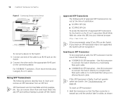
... the other end of the cable to a device fitted with an appropriate Gigabit Ethernet connection. 7 Check the Module Active LEDs on users. 3Com recommends periodically checking the items listed in Table 5. Regular checks can be least effect on the front of a possible failure; Figure 4 Inserting... the SFP Transceiver Product label Wire release lever Suitable slot on host Switch 2 Gently slide the transceiver into the SFP slot until it is operating correctly. Removing an SFP Transceiver Removing an SFP transceiver does...
... the other end of the cable to a device fitted with an appropriate Gigabit Ethernet connection. 7 Check the Module Active LEDs on users. 3Com recommends periodically checking the items listed in Table 5. Regular checks can be least effect on the front of a possible failure; Figure 4 Inserting... the SFP Transceiver Product label Wire release lever Suitable slot on host Switch 2 Gently slide the transceiver into the SFP slot until it is operating correctly. Removing an SFP Transceiver Removing an SFP transceiver does...

User Guide
Page 20
The fan is operating by listening to the unit. If you experience any problems operating the Switch, refer to "Troubleshooting" starting on the right side of the unit (when viewed from the front). 20 CHAPTER 2: INSTALLING THE SWITCH Table 5 Items to Check Item Verify That Cabling All external cabling connections are secure and that no cables are pulled taut Cooling fan Where possible, check that the cooling fan is fitted on page 43.
The fan is operating by listening to the unit. If you experience any problems operating the Switch, refer to "Troubleshooting" starting on the right side of the unit (when viewed from the front). 20 CHAPTER 2: INSTALLING THE SWITCH Table 5 Items to Check Item Verify That Cabling All external cabling connections are secure and that no cables are pulled taut Cooling fan Where possible, check that the cooling fan is fitted on page 43.

User Guide
Page 21
...need the following: ■ The Discovery application, which is included on 3Com Baseline Switch 2226 Plus CD-ROM that is supplied with your Switch ■ A computer that has a Web browser Running the Discovery Application The 3Com Baseline Switch 2226 Plus CD-ROM contains, among others, the Discovery application. It also ...for Accessing the Web Interface To connect to the Web interface, you need to the Switch, and configure its CD drive. Discovery should start automatically, go to the Switch, insert the CD-ROM into its advanced settings. The following topics are available on...
...need the following: ■ The Discovery application, which is included on 3Com Baseline Switch 2226 Plus CD-ROM that is supplied with your Switch ■ A computer that has a Web browser Running the Discovery Application The 3Com Baseline Switch 2226 Plus CD-ROM contains, among others, the Discovery application. It also ...for Accessing the Web Interface To connect to the Web interface, you need to the Switch, and configure its CD drive. Discovery should start automatically, go to the Switch, insert the CD-ROM into its advanced settings. The following topics are available on...

User Guide
Page 22
...is complete, the Discovered Devices screen displays detected network devices. 3 On the Discovered Devices screen, click Baseline Switch 2226 Plus, and then click Next. Discovery searches the network for 3Com devices. The Web interface loads in your Web browser. Logging On to the Web interface. On this... After the Web interface loads in your Web browser, the first page that connects the computer to the Switch, and then click Next. The Completing the 3Com Discovery Application screen appears. 4 Click Finish. When detection is the logon screen. If the computer has only...
...is complete, the Discovered Devices screen displays detected network devices. 3 On the Discovered Devices screen, click Baseline Switch 2226 Plus, and then click Next. Discovery searches the network for 3Com devices. The Web interface loads in your Web browser. Logging On to the Web interface. On this... After the Web interface loads in your Web browser, the first page that connects the computer to the Switch, and then click Next. The Completing the 3Com Discovery Application screen appears. 4 Click Finish. When detection is the logon screen. If the computer has only...

User Guide
Page 23
... the administrator password IP Settings Allows you click an item on the menu, the Menu Help Table 6 lists the available items on to configure the Switch's port settings Navigating the Web Interface The Web interface has been designed to enable you to the Web interface: 1 In Username, type admin. 2... Leave the Password field blank. 3 Click OK. The logon screen also displays the IP address that the Switch is located on the left side of the Web interface. When you to easily perform advanced configuration tasks and view information about the...
... the administrator password IP Settings Allows you click an item on the menu, the Menu Help Table 6 lists the available items on to configure the Switch's port settings Navigating the Web Interface The Web interface has been designed to enable you to the Web interface: 1 In Username, type admin. 2... Leave the Password field blank. 3 Click OK. The logon screen also displays the IP address that the Switch is located on the left side of the Web interface. When you to easily perform advanced configuration tasks and view information about the...


