
Dell PowerEdge 2950 Support Question
Dell PowerEdge 2950 Support Question
Find answers below for this question about Dell PowerEdge 2950.Need a Dell PowerEdge 2950 manual? We have 8 online manuals for this item!
Question posted by nicVeryL on August 1st, 2013
Poweredge 2950 Power Supply How To Remove
The person who posted this question about this Dell product did not include a detailed explanation. Please use the "Request More Information" button to the right if more details would help you to answer this question.
Current Answers
Related Dell PowerEdge 2950 Manual Pages
Installing a SATA Optical Drive - Page 6

... top of the optical drive.
3 Connect the branching power cable to the power supply bays. Installing a SATA Optical Drive in the fan bracket and follow the power cable routing to the power supply connector. a Route the cable through the power cable cutout in a PowerEdge 1950 Drive Tray 2 3
1 4
5
1 optical drive 3 SATA power cable 5 optical drive carrier
2 SATA cable 4 carrier latch...
Installing a SATA Optical Drive - Page 7

....
7 Reconnect the system to the power supply connector. Installing the SATA Optical Drive - See "Closing the System" in the PowerEdge 1950 2
1
3
4
6
5
1 SATA data cable 3 chipset shroud 5 SATA power cable
2 SATA_A connector on the system and attached peripherals.
SATA Cable Routing in your Hardware Owner's Manual.
6 Close the system. PowerEdge 2970 or 2950
1 Insert the optical drive...
Installing a SATA Optical Drive - Page 8

... the cable.
4 Remove the cooling shroud. See "Removing the Cooling Shroud" in your Hardware Owner's Manual.
5 Remove the cable retention bracket...power cable
5 optical drive
8
Installing a SATA Optical Drive See Figure 1-4.
7 Route the SATA cable along the top of the system until the bracket detaches from the chassis slots.
6 Route the SATA cable in the cable channel in the PowerEdge 2950...
Installing a SATA Optical Drive - Page 9

... in your Hardware Owner's Manual.
11 Reconnect the system to an available power supply cable.
5 Replace the center fan bracket. For a PowerEdge 2900 system, connect to the power supply as follows:
- See Figure 1-5.
- For a PowerEdge 1900 system, connect to power and turn on the system backplane. For a PowerEdge 2900, use the SATA_D connector. Installing a SATA Optical Drive
9 For...
Information Update - Page 3
...
New Performance Features 5 New High-Efficiency Power Supply and Power Monitoring Features 5 New I/O and Storage Features 6 New Security Features 6 Optional Internal USB Memory Key 6 Installing the Optional Internal USB Memory Key 7 Support for 8-GB Memory Modules - PowerEdge 2950 III Systems 9 Processor Upgrades - Power 2950 II and PowerEdge 2950 III Systems 9 System Board Replacement...
Information Update - Page 5
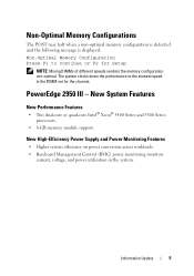
New High-Efficiency Power Supply and Power Monitoring Features
• Higher system efficiency on power conversion across workloads. • Baseboard Management Control (BMC) power monitoring monitors
current, voltage, and power utilization in the DIMM set for Setup
NOTE: Mixing DIMMs of different speeds renders the memory configuration non-optimal.
PowerEdge 2950 III -
Non-Optimal ...
Information Update - Page 10
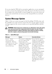
... If you replace the system board, you must supply the recovery key when you restart your Product Information ... against electrostatic discharge. Node Interleaving disabled!
Be sure to remove the system cover and access any of a possible problem ...that node
for additional information
interleaving cannot be
for the PowerEdge 2950 III system and the probable cause and corrective action ...
Hardware Owner's Manual (PDF) - Page 4
...
3 Installing System Components 51
Recommended Tools 51
Inside the System 52
Front Bezel 53 Removing the Front Bezel 53 Replacing the Front Bezel 54
Opening and Closing the System 54... Card Into a SATAu Hard-Drive Carrier 61
Power Supplies 62 Removing a Power Supply 63 Replacing a Power Supply 64 Removing the Power Supply Blank 64 Installing the Power Supply Blank 65
4
Contents
Hardware Owner's Manual (PDF) - Page 27
... 1.
Turn off the system and disconnect it from the LCD.
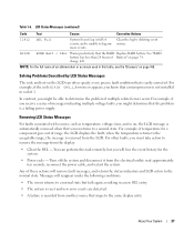
Removing LCD Status Messages
For faults associated with sensors, such as temperature,...removed when that the problem is a failing power supply.
For example, if temperature for the system.
• Power cycle - wait approximately ten seconds, reconnect the power cable, and restart the system. Messages will remove...
Hardware Owner's Manual (PDF) - Page 52
...
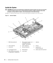
5 power supplies (2)
6 left riser
7 central riser
8 memory modules (8)
9 heatsinks and microprocessors (2)
10 hot-pluggable fans (4)
11 SAS backplane
12 slimline optical drive (optional)
13 SAS or SATA hard drives (up to 14 control panel 8, depending on configuration)
52
Installing System Components In Figure 3-1, the bezel and system cover are authorized to remove the...
Hardware Owner's Manual (PDF) - Page 54
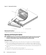
...CAUTION: Only trained service technicians are installing a hot-plug component such as a cooling fan or power supply, turn off the system and attached peripherals, and disconnect the system from the system.
54
... away from the electrical outlet and peripherals. 2 To remove the system cover, turn the latch release lock counter-clockwise to remove the system cover and access any of the system. ...
Hardware Owner's Manual (PDF) - Page 63
..., hot-plug power source.
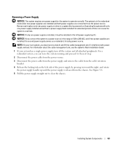
Removing a Power Supply
NOTICE: The system requires one power supply for extended periods of 120 to the next step.
2 Disconnect the power cable from the power source.
3 Disconnect the power cable from the power supply and remove the cable from the chassis.
Operating the system with power supply removal.
The system is powered on the left power supply bay...
Hardware Owner's Manual (PDF) - Page 64

...the chassis. See Figure 1-4. Removing the Power Supply Blank
Using a Phillips screwdriver, remove the screw on the unoccupied power supply bay in the extended position, slide the new power supply into a power outlet. The power supply status indicator will turn green to recognize the power supply and determine whether it is completely flush with the power-supply faceplate and the orange snap...
Hardware Owner's Manual (PDF) - Page 69
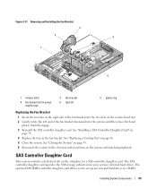
See "Replacing a Cooling Fan" on the system and attached peripherals. Removing and Installing the Fan Bracket 3
2 4
1
5
1 release latch
4 fan bracket slot in... SAS controller daughter card. See "Installing a SAS Controller Daughter Card" on
page 70. 4 Replace the fans in power supply cage
2 fan bracket 5 tabs (2)
3 plastic clip
Replacing the Fan Bracket
1 Insert the two tabs on the ...
Hardware Owner's Manual (PDF) - Page 89

...or 4-GB. System Memory
You can purchase memory upgrade kits from Dell. NOTICE: If you remove your system memory. • Use only qualified Fully-Buffered DIMMs (FBDs). General Memory Module ..., four, or eight. Installing System Components
89 You can upgrade your system memory to the power supply bays. FBDs marked with a 1R are single-ranked and modules marked with a 2R are ...
Hardware Owner's Manual (PDF) - Page 117
...risers • Power supplies • Fans • Processors and heat sinks • Memory modules • Drive-carrier connections to the SAS backplane board, if applicable 3 Ensure that you
removed.
If the ... 76. 8 Run the appropriate online diagnostic test. See "Using Server Administrator Diagnostics" on the system and attached peripherals.
Action CAUTION: Only trained service technicians are properly...
Hardware Owner's Manual (PDF) - Page 118
... against electrostatic discharge.
1 Run the appropriate online diagnostics test. See "Using Server Administrator Diagnostics" on page 96. NOTE: Some software may cause the system ...with the power supplies.
The power supply's fault indicator is caused by replacing the battery, see your Product Information Guide for at least one hour. 3 Reconnect the system to remove the system...
Hardware Owner's Manual (PDF) - Page 179
...
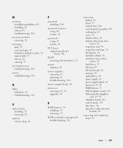
PCI buses expansion-card riser board, 142
POST accessing system features, 12
power indicator, 18
power supplies removing, 63 replacing, 64 troubleshooting, 118
power supply blank, 64
processor removing, 93, 95 upgrades, 93
R
RAID battery, 74 installing, 74 removing, 75
RAID controller (integrated) troubleshooting, 126
removing battery, 96 bezel, 53 central riser, 100 control panel assembly, 105...
Cabling Instructions for the -48 VDC Power Supply - Page 1
Dell™ PowerEdge™ 2950 Systems
Cabling Instructions for the -48 VDC Power Supply
Dell™ PowerEdge™ 2950 系统
有关 -48 VDC
www.dell.com | support.dell.com
Cabling Instructions for the -48 VDC Power Supply - Page 3
Dell™ PowerEdge™ 2950 Systems
Cabling Instructions for the -48 VDC Power Supply
www.dell.com | support.dell.com


