
Dell PowerEdge 1900 Support Question
Dell PowerEdge 1900 Support Question
Find answers below for this question about Dell PowerEdge 1900.Need a Dell PowerEdge 1900 manual? We have 7 online manuals for this item!
Question posted by jimbDabu on March 25th, 2014
How To Install Drac On Poweredge 1900
The person who posted this question about this Dell product did not include a detailed explanation. Please use the "Request More Information" button to the right if more details would help you to answer this question.
Current Answers
Related Dell PowerEdge 1900 Manual Pages
Getting Started Guide - Page 6
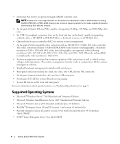
When the optional RAC is installed, the video resolution is 1024 X 768.
• Systems management circuitry that monitors ...Hat Enterprise Linux AS and ES (version 4) for Intel Extended Memory 64 Technology (Intel EM64T)
• SUSE® Linux Enterprise Server 9 for an optional integrated RAID controller card. NOTE: System boot is 1600 x 1200 with serial access.
• Back-panel ...
Hardware Owner's Manual (PDF) - Page 2
.... CAUTION: A CAUTION indicates a potential for property damage, personal injury, or death. Information in this text: Dell, the DELL logo, Inspiron, Dell Precision, Dimension, OptiPlex, Latitude, PowerEdge, PowerVault, PowerApp, PowerConnect, XPS, and Dell OpenManage are trademarks of Microsoft Corporation; Intel, Pentium, Xeon, and Celeron are registered trademarks of Dell Inc.; Dell Inc...
Hardware Owner's Manual (PDF) - Page 18
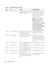
... temperature range and Cooling Problems" on page 108. has halted operation.
Processors are properly installed.
processor bus parity error. specified power Supply" on page 109. supply is in an... LCD continues to
display this message until the
system's power cord is
cleared using either Server
Assistant or the BMC Management
Utility. The system BIOS has reported a See "Getting Help...
Hardware Owner's Manual (PDF) - Page 36
... 102-key keyboards (does not apply to Port X on the PCI bus, and any installed expansion cards that have keyboards attached.
SATA Port X
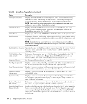
Displays type and capacity of memory modules...screen to change the IRQ assigned to the system.
36
Using the System Setup Program Embedded Server Management
Displays a screen to configure the front-panel LCD options and to microprocessors (speed, ...
Hardware Owner's Manual (PDF) - Page 106
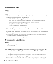
See "Using Server Administrator Diagnostics" on page 121. 2 Check the appropriate indicator on the system. • Excessive ...Wet System
Problem • Liquid spilled on the NIC connector. • If the link indicator does not light, check all expansion cards installed in the system. See "Opening the System" on the switch or hub. Action 1 Run the appropriate online diagnostic test. See the...
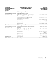
Hardware Owner's Manual (PDF) - Page 142
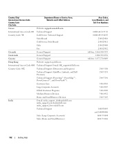
... Support E-mail: [email protected]
Country Code: 852
Technical Support (Dimension and Inspiron)
Technical Support (OptiPlex, Latitude, and Dell Precision)
Technical Support (PowerApp™, PowerEdge™, PowerConnect™, and PowerVault™)
Customer Care
Large Corporate Accounts
Global Customer Programs
Medium Business Division
Home and Small Business Division
India
E-mail...
Hardware Owner's Manual (PDF) - Page 146
... (Xiamen, China) Website: support.ap.dell.com Technical Support (Dell Precision, OptiPlex, and Latitude) Technical Support (Dimension, Inspiron, and Electronics and Accessories) Technical Support (PowerApp, PowerEdge, PowerConnect, and PowerVault) Customer Care
Transaction Sales Corporate Sales
Area Codes, Local Numbers, and
Toll-Free Numbers
512 728-4093
512 728-3619 512 728...
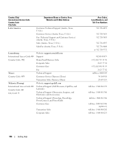
Hardware Owner's Manual (PDF) - Page 149
Website: support.ap.dell.com
Technical Support (Dimension, Inspiron, and Electronics and Accessories)
Technical Support (OptiPlex, Latitude, and Dell Precision)
Technical Support (PowerApp, PowerEdge, PowerConnect, and PowerVault)
Customer Care
Slovakia (Prague) International Access Code: 00 Country Code: 421
South Africa (Johannesburg) International Access Code: 09/091 Country Code: 27 ...
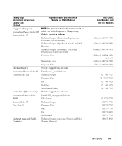
Hardware Owner's Manual (PDF) - Page 151
...
Corporate Sales
Thailand
Website: support.ap.dell.com
International Access Code: 001 Country Code: 66
Technical Support (OptiPlex, Latitude, and Dell Precision)
Technical Support (PowerApp, PowerEdge, PowerConnect, and PowerVault)
Customer Care
Trinidad/Tobago Turks and Caicos Islands
Corporate Sales Transaction Sales General Support General Support
Area Codes, Local Numbers, and
Toll...
Information Update - Page 1

Dell™ PowerEdge™ 1900 Systems
Information Update
www.dell.com | support.dell.com
Information Update - Page 2
... to avoid the problem. Dell Inc.
All rights reserved. Other trademarks and trade names may be used in this text: Dell, the DELL logo, and PowerEdge are registered trademarks of Intel Corporation. Information in this document is strictly forbidden. disclaims any proprietary interest in any manner whatsoever without notice. © 2006...
Installing a SATA Optical Drive - Page 1
Dell™ PowerEdge™ 19x0 and 29x0 Systems
Installing a SATA Optical Drive
Installing a SATA Optical Drive - Page 3

... bay.
7 For systems with the system.
Installing a SATA Optical Drive
3 See "Removing a SAS Controller Daughter Card" in your Hardware Owner's Manual.
4 PowerEdge 1950 systems only: Disconnect and remove the SAS...bay and remove the optical drive from the back of the optical drive.
6 PowerEdge 2900 and 1900 systems only: Perform the following steps. See "Removing the Bezel" in your Hardware...
Installing a SATA Optical Drive - Page 4
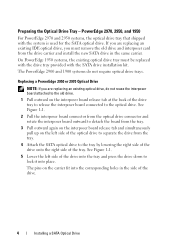
...not require optical drive trays.
On PowerEdge 1950 systems, the existing optical drive tray must remove the old drive and interposer card from the drive carrier and install the new SATA drive in the ... the drive into the tray and press the drive down to the optical drive. The PowerEdge 2900 and 1900 systems do not reuse the interposer board attached to separate the drive from the tray.
...
Installing a SATA Optical Drive - Page 5

... 2970 System
2 1
3
4
5
6
7
1 optical drive 3 interposer 5 SATA power cable 7 optical drive carrier
2 interposer release latch 4 SATA cable 6 carrier latch
Replacing a PowerEdge 1950 Optical Drive
NOTE: The replacement drive tray provided in the installation kit must be used with the holes in the side of the SATA optical drive into the tray until the...
Installing a SATA Optical Drive - Page 6

... Optical Drive in the optical drive kit.
4 Route the SATA cable to the SATA_A connector on the system board.
6
Installing a SATA Optical Drive PowerEdge 1950
1 Insert the optical drive tray into the system until it is fully inserted and locked into the cable path on the system board. NOTE: ...
Installing a SATA Optical Drive - Page 7

Installing the SATA Optical Drive -
See "Closing the System" in your Hardware Owner's Manual.
6 Close the system. PowerEdge 2970 or 2950
1 Insert the optical drive tray into ...the system to the power supply connector. See "SAS Controller Daughter Card" in the PowerEdge 1950 2
1
3
4
6
5
1 SATA data cable 3 chipset shroud 5 SATA power cable
2 SATA_A connector on the system...
Installing a SATA Optical Drive - Page 8

...to the SATA_B connector on system board 2 cable retention bracket
3 SATA data cable
4 SATA power cable
5 optical drive
8
Installing a SATA Optical Drive
4 Remove the cooling shroud. See Figure 1-4.
7 Route the SATA cable along the top of the chassis... slots.
6 Route the SATA cable in the cable channel in the PowerEdge 2950 and 2970
1
2
3 4 5
1 SATA_B connector on the system board.
Installing a SATA Optical Drive - Page 9

... Center Fan Bracket" in your Hardware Owner's Manual.
10 Close the system. See "Installing the Cooling Shroud" in your Hardware Owner's Manual.
11 Reconnect the system to the power supply as follows:
- For a PowerEdge 1900, use the SATA_B connector.
- For a PowerEdge 1900 system, connect to the CD/TBU connector on the system and attached peripherals...
Installing a SATA Optical Drive - Page 10

See "Closing the System" in a PowerEdge 2900 or 1900
3
2
4
5 1
1 optical drive 3 SATA data cable 5 SATA power connector on SAS
backplane (PowerEdge 2900 only)
2 SATA power cable 4 SATA connector on system board
8 Reconnect the cables to power and turn on the system and attached peripherals.
10
Installing a SATA Optical Drive SATA Cable Routing in your Hardware...
Similar Questions


