Dell OptiPlex 990 Support Question
Dell OptiPlex 990 Support Question
Find answers below for this question about Dell OptiPlex 990.Need a Dell OptiPlex 990 manual? We have 3 online manuals for this item!
Question posted by jondkh on August 11th, 2014
Optiplex 990 Wont Boot Diagnostic Light 1,3,4
The person who posted this question about this Dell product did not include a detailed explanation. Please use the "Request More Information" button to the right if more details would help you to answer this question.
Current Answers
Answer #1: Posted by DellJesse1 on August 11th, 2014 10:59 AM
DellJesse1

Member since:
April 19th, 2012 Points: 1,551,500

Member since:
April 19th, 2012 Points: 1,551,500
jondkh,
Below is what the error code LED's 1,3,4 represent and what to do to resolve.
"A possible system board resource and/or hardware failure has occurred."
Resolution:
- Clear CMOS.
- Disconnect all internal and external peripherals, and restart the computer. If the computer boots, add the peripheral cards back one by one until you find the bad one.
- If the problem persists, the system board / system board component is probably bad.
Thank You,
Dell-Jesse1
Dell Social Media and Communities
email:[email protected]
Dell Community Forum.
www.en.community.dell.com
Dell Twitter Support
@dellcares
Dell Facebook Support
www.facebook.com/dell
#iwork4dell
Related Dell OptiPlex 990 Manual Pages
User Manual - Page 1
... OptiPlex 990
Setup And Features Information
About Warnings
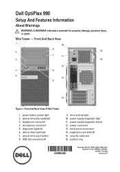
WARNING: A WARNING indicates a potential for property damage, personal injury, or death. Mini Tower - Front And Back View Of Mini Tower
1. microphone connector 5. back panel connectors 14. optical-drive bay (optional) 3. optical-drive eject button 8. headphone connector 4. power button, power light 2. diagnostic lights...
User Manual - Page 2
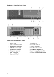
... eject button 3. power button, power light 4. Desktop - USB 2.0 connectors (4) 5. microphone connector 6. padlock ring 10. Front And Back View Of Desktop
1. back panel connectors 13. headphone connector 7. expansion-card slots (4) 14. diagnostic lights (4)
9. power connector 12. drive activity light 8. power supply diagnostic light 15. security-cable slot 11. power...
User Manual - Page 3
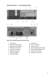
... button 13. back panel connectors 15. expansion-card slots (2)
3 optical drive 2. USB 2.0 connectors (4) 5. diagnostic lights (4) 8. power button, power light 4. microphone connector 6. headphone connector 7. power supply diagnostic light 14. padlock ring 10. Front And Back View
Figure 3. power connector 12. Front And Back View Of Small Form Factor
1. drive activity...
User Manual - Page 4
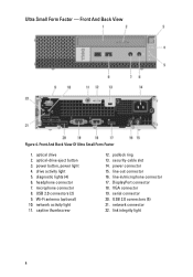
...VGA connector 19. Wi-Fi antenna (optional) 10. Ultra Small Form Factor - microphone connector 8. optical drive 2. diagnostic lights (4) 6. optical-drive eject button 3. Front And Back View Of Ultra Small Form Factor
1. power button, power light 4. headphone connector 7. line-in/microphone connector 17. USB 2.0 connectors (5) 21. network connector 22. link...
User Manual - Page 10
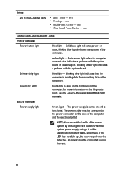
...-on the front panel of the computer) and the electrical outlet. Blinking amber light indicates a problem with the system board or power supply. one
Control Lights And Diagnostic Lights Front of computer
Power supply light
Green light -
Diagnostic lights
Four lights located on state;
Amber light - AC power must be connected to the hard drive. The power cable must...
Technical Guide - Page 1
INSIDE THE OPTIPLEX 990 DELL TM OPTIPLEX TM 990
TECHNICAL GUIDEBOOK-
Technical Guide - Page 3
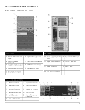
DELL™ OPTIPLEX™ 990 TECHNICAL GUIDEBOOK -V 1.0 MINI TOWER COMPUTER (MT) VIEW
FRONT VIEW
BACK VIEW
1 Power Button, Power Light
6 Optical Drive (optional)
10 Power Supply Diagnostic 14 Expansion Card Slots(4) Light
2 Optical Drive Bay (optional)
3 Headphone Connector
4 Microphone Connector
7 Optical Drive Eject Button 8 USB 2.0 Connectors (4) 9 Drive Activity Light
11 Power ...
Technical Guide - Page 4
DELL™ OPTIPLEX™ 990 TECHNICAL GUIDEBOOK -V 1.0
MT System Board Components
Number
Name
Number
Name
1
Internal Speaker Connector (INT_SPKR)
13
PCI Connector(SLOT3)
2
Front IO Connector (FRONTPANEL)
3
Thermal Sensor Connector(...
Technical Guide - Page 5
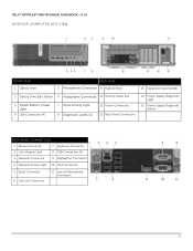
DELL™ OPTIPLEX™ 990 TECHNICAL GUIDEBOOK -V 1.0 DESKTOP COMPUTER (DT) VIEW
FRONT VIEW 1 Optical Drive
BACK VIEW 5 Microphone Connector 9 Padlock Ring
13 Expansion Card Slots(4)
2 Optical Drive Eject Button 6 Headphone Connector 10 Security Cable Slot
3 Power Button, Power Light
4 USB Connectors (4)
7 Drive Activity Light 8 Diagnostic Lights (4)
11 Power Connectors 12 Back Panel ...
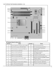
Technical Guide - Page 6
DELL™ OPTIPLEX™ 990 TECHNICAL GUIDEBOOK -V 1.0
DT System Board Components
Number
Name
1
Internal Speaker Connector
(INT_SPKR)
2
Front IO Connector (FRONTPANEL)
3
Thermal Sensor Connector(THRM_2)
4
SATA 0 Connector(SATA0)
5
SATA 1 Connector(...
Technical Guide - Page 7
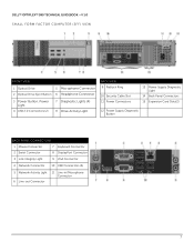
...; OPTIPLEX™ 990 TECHNICAL GUIDEBOOK -V 1.0 SMALL FORM FACTOR COMPUTER (SFF) VIEW
FRONT VIEW
1 Optical Drive
5 Microphone Connector
2 Optical Drive Eject Button 6 Headphone Connector
3 Power Button, Power Light
4 USB 2.0 Connectors (2)
7 Diagnostic Lights (4) 8 Drive Activity Light
BACK VIEW 9 Padlock Ring
10 Security Cable Slot 11 Power Connectors
13 Power Supply Diagnostic Light
14...
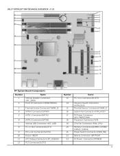
Technical Guide - Page 8
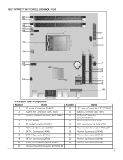
DELL™ OPTIPLEX™ 990 TECHNICAL GUIDEBOOK -V 1.0
SFF System Board Components
Number
Name
1
P1 power Connector (POWER)
2
System fan Connector (FAN_HDD)
3
Internal Speaker Connector (INT_SPKR)
4
Buzzer (BEEP)
5
PCI-e 4x Connector(...
Technical Guide - Page 9
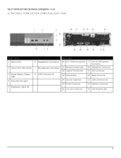
...8482; OPTIPLEX™ 990 TECHNICAL GUIDEBOOK -V 1.0 ULTRA SMALL FORM FACTOR COMPUTER (USFF) VIEW
FRONT VIEW 1 Optical Drive
2 Optical Drive Eject Button
3 Power Button, Power Light
4 Drive Activity Light
5 Diagnostic Lights (4)
6 Headphone Connector 7 Microphone Connector 8 USB Connectors (2)
BACK VIEW
10 Wi-Fi Antenna (optional) 17 Line-in/ Microphone Connector
11 Network Activity Light 18...
Technical Guide - Page 10
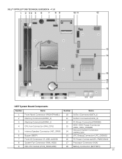
DELL™ OPTIPLEX™ 990 TECHNICAL GUIDEBOOK -V 1.0
USFF System Board Components
Number
Name
Number
Name
1
Front Panel Connector (FRONTPANEL)
10
SATA 1 Connector(SATA_1)
2
Memory Connector(DIMM_2)
11
SATA 0 Connector(SATA_0)
3
...
Technical Guide - Page 11
no dedicated
LOM EEPROM
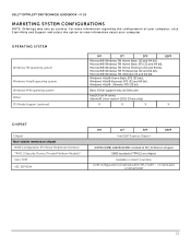
11 DELL™ OPTIPLEX™ 990 TECHNICAL GUIDEBOOK -V 1.0
MARKETING SYSTEM CONFIGURATIONS
NOTE: Offerings may vary by country. For more information regarding the configuration of your computer, click Start>Help and Support ...
Technical Guide - Page 12
... implement global IT standards by region/ country.
The following GSP processors identified below will be made available to reduce the number of performance.
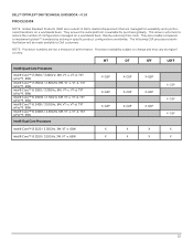
DELL™ OPTIPLEX™ 990 TECHNICAL GUIDEBOOK -V 1.0 PROCESSOR
NOTE: Global Standard Products (GSP) are a subset of Dell's relationship products that are not a measure of configurations managed on a worldwide basis...
Technical Guide - Page 13
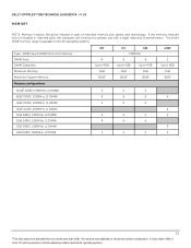
... in pairs of memory requires a 64-bit enabled processor and 64-bit operating system. The amount less depends on the actual system configuration. DELL™ OPTIPLEX™ 990 TECHNICAL GUIDEBOOK -V 1.0 MEMORY
NOTE: Memory modules should be less than 4GB. To fully utilize 4GB or more of matched memory size, speed, and technology...
Technical Guide - Page 23
DELL™ OPTIPLEX™ 990 TECHNICAL GUIDEBOOK -V 1.0
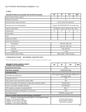
AUDIO
INTEGRATED REALTEK ALC269Q HIGH DEFINITION AUDIO High Definition ... Power consumption (standby operation) IEEE standards compliance (example 802.1P) Hardware Certifications (example FCC, B, GS mark...) Boot ROM Support Network Transfer Mode (example Full Duplex, Half Duplex)
Network Transfer Rate (example 10BASE-T (half-duplex)...
Technical Guide - Page 24
... standards compliance (example 802.1P)
Hardware Certifications (example FCC, B, GS mark...)
Boot ROM Support
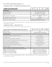
Network Transfer Mode (example Full Duplex, Half Duplex) Network Transfer Rate ...cards and DT and SFF supports low profile (LP) cards. COMMUNICATIONS - DELL™ OPTIPLEX™ 990 TECHNICAL GUIDEBOOK -V 1.0 COMMUNICATIONS - For high speed transmission, connection to a Gigabit Ethernet...
Technical Guide - Page 43
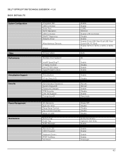
DELL™ OPTIPLEX™ 990 TECHNICAL GUIDEBOOK -V 1.0 BIOS DEFAULTS
System Configuration
Video Performance Virtualization Support Security
Power Management... Wake on LAN:
Service Tag: Asset Tag: SERR Message:
Numlock LED: USB Emulation: Keyboard Errors: POST HotKeys: Fast Boot:
Enable Enable COM1 RAID On Enable USB Controller Disable Enable Enable (Front USB, Rear Dual USB, Rear Quad USB, PCI...
Similar Questions


