
eMachines EL1852 Service Guide
Page 7
... Fan Assembly 26 Removing the Processor 27 Removing the HDD-ODD Bracket 28 Removing the Expansion Boards 33 Removing the Memory Modules 35 Removing the Power Supply Unit 35 Removing the Front I/O and Card Reader Assembly 37 Removing the Mainboard 40 Hardware Diagnostic Procedure 41 System Check Procedures 41 Checkpoints 42 POST Error Indicators 46 BIOS Recovery 58 BIOS Update 59 Clearning CMOS 63 System Architecture 65 Block Diagram 65 Mainboard Layout 66 Jumper Setting 67 Setting Jumper 68 Connecting Optional Devices 69 Connecting Case...
... Fan Assembly 26 Removing the Processor 27 Removing the HDD-ODD Bracket 28 Removing the Expansion Boards 33 Removing the Memory Modules 35 Removing the Power Supply Unit 35 Removing the Front I/O and Card Reader Assembly 37 Removing the Mainboard 40 Hardware Diagnostic Procedure 41 System Check Procedures 41 Checkpoints 42 POST Error Indicators 46 BIOS Recovery 58 BIOS Update 59 Clearning CMOS 63 System Architecture 65 Block Diagram 65 Mainboard Layout 66 Jumper Setting 67 Setting Jumper 68 Connecting Optional Devices 69 Connecting Case...
eMachines EL1852 Service Guide
Page 9
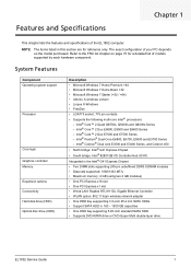
... bay supporting 5.25-inch standard SATA ODD • Supports DVD-R/RW drive or DVD-Super Multi double-layer drive EL1852 Service Guide 1 Intel® Core™ 2 Quad Q9550s, Q9400s and Q8400s Series - Intel® Pentium® Dual-Core E6800, E6700, E5800 and E5700 Series - The exact configuration of the EL1852 computer. System Features Component Operating system support Processor Core logic Graphics controller Memory Expansion options Connectivity Hard disk drive (HDD) Optical disc drive (ODD) Description • Microsoft Windows 7 Home...
... bay supporting 5.25-inch standard SATA ODD • Supports DVD-R/RW drive or DVD-Super Multi double-layer drive EL1852 Service Guide 1 Intel® Core™ 2 Quad Q9550s, Q9400s and Q8400s Series - Intel® Pentium® Dual-Core E6800, E6700, E5800 and E5700 Series - The exact configuration of the EL1852 computer. System Features Component Operating system support Processor Core logic Graphics controller Memory Expansion options Connectivity Hard disk drive (HDD) Optical disc drive (ODD) Description • Microsoft Windows 7 Home...
eMachines EL1852 Service Guide
Page 15
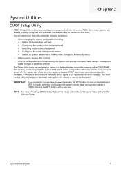
... date • Configuring the system drives and peripherals • Specifying the boot device sequence • Configuring the power management modes • Setting up system passwords or making other changes to the security setup • When trying to configure the hardware. You must run this utility. EL1358 Service Guide 7 POST uses these values to resolve IRQ conflicts • When a configuration error is booted. In this utility to the BIOS settings. The Setup Utility loads the configuration values in CMOS. NOTE For...
... date • Configuring the system drives and peripherals • Specifying the boot device sequence • Configuring the power management modes • Setting up system passwords or making other changes to the security setup • When trying to configure the hardware. You must run this utility. EL1358 Service Guide 7 POST uses these values to resolve IRQ conflicts • When a configuration error is booted. In this utility to the BIOS settings. The Setup Utility loads the configuration values in CMOS. NOTE For...

eMachines EL1852 Service Guide
Page 20
...EL1358 Service Guide Advanced BIOS Feature Field Quick Boot Quiet Boot 1st/2nd/3rd/4th Boot Device Hard Disk Drive Priority Optical Disk Drive Priority Removable Device Priority Network Device Priority Bootup Num-Lock Boot Sector Virus Protection USB Beep Message Description Value When enabled, the system starts up . Enabled Disabled Displays the device assigned to emit error beeps or display error messages during USB device enumeration. Press Enter to specify the boot device priority sequence for boot devices in this item to access the boot sector or hard disk partition table...
...EL1358 Service Guide Advanced BIOS Feature Field Quick Boot Quiet Boot 1st/2nd/3rd/4th Boot Device Hard Disk Drive Priority Optical Disk Drive Priority Removable Device Priority Network Device Priority Bootup Num-Lock Boot Sector Virus Protection USB Beep Message Description Value When enabled, the system starts up . Enabled Disabled Displays the device assigned to emit error beeps or display error messages during USB device enumeration. Press Enter to specify the boot device priority sequence for boot devices in this item to access the boot sector or hard disk partition table...
eMachines EL1852 Service Guide
Page 31
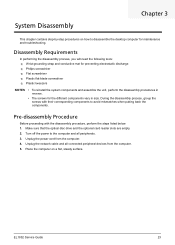
... back the components. Turn off the power to disassemble the desktop computer for the different components vary in size. Unplug the power cord from the computer. 5. EL1852 Service Guide 23 Place the computer on how to the computer and all connected peripheral devices from the computer. 4. Unplug the network cable and all peripherals. 3. Make sure that the optical disc drive and the optional card reader slots are empty. 2. System...
... back the components. Turn off the power to disassemble the desktop computer for the different components vary in size. Unplug the power cord from the computer. 5. EL1852 Service Guide 23 Place the computer on how to the computer and all connected peripheral devices from the computer. 4. Unplug the network cable and all peripherals. 3. Make sure that the optical disc drive and the optional card reader slots are empty. 2. System...
eMachines EL1852 Service Guide
Page 49
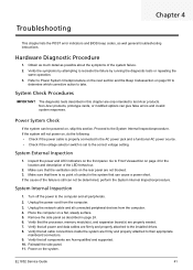
... the failure is set to the computer and all power and data cables are properly seated. 7. Troubleshooting Chapter 4 This chapter lists the POST error indicators and BIOS beep codes, as described in page 24. 6. Non-Acer products, prototype cards, or modified options can cause a power short. Make sure that all cable connections inside the system are only intended to the System Internal Inspectionprocedure. Verify that the ventilation slots on...
... the failure is set to the computer and all power and data cables are properly seated. 7. Troubleshooting Chapter 4 This chapter lists the POST error indicators and BIOS beep codes, as described in page 24. 6. Non-Acer products, prototype cards, or modified options can cause a power short. Make sure that all cable connections inside the system are only intended to the System Internal Inspectionprocedure. Verify that the ventilation slots on...
eMachines EL1852 Service Guide
Page 51
... interrupt vectors are based on CMOS setup questions. Set up floppy controller and data. Start reading FAT table and analyze FAT to BIOS POST (ExecutePOSTKernel). Make flash write enabled through chipset and OEM specific method. Verify that a BIOS recovery needs to occur because the user has forced the update or the BIOS checksum is corrupt. Make flash write disabled. Also initialize BIOS modules on media. Verify CMOS checksum manually by cluster. If the...
... interrupt vectors are based on CMOS setup questions. Set up floppy controller and data. Start reading FAT table and analyze FAT to BIOS POST (ExecutePOSTKernel). Make flash write enabled through chipset and OEM specific method. Verify that a BIOS recovery needs to occur because the user has forced the update or the BIOS checksum is corrupt. Make flash write disabled. Also initialize BIOS modules on media. Verify CMOS checksum manually by cluster. If the...
eMachines EL1852 Service Guide
Page 52
... and initializes the video adapter installed in PIC for more information. Detect different devices (Parallel ports, serial ports, and coprocessor in the system and update the BDA, EBDA...etc. Programming the memory hole or any platform specific BIOS modules. Enable IRQ-0 in the system that the POST INT09h handler gets control for IRQ1. Initializes different devices. Initializes the silent boot module. See DIM Code Checkpoints section...
... and initializes the video adapter installed in PIC for more information. Detect different devices (Parallel ports, serial ports, and coprocessor in the system and update the BDA, EBDA...etc. Programming the memory hole or any platform specific BIOS modules. Enable IRQ-0 in the system that the POST INT09h handler gets control for IRQ1. Initializes different devices. Initializes the silent boot module. See DIM Code Checkpoints section...
eMachines EL1852 Service Guide
Page 53
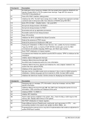
... MTRR values. Check boot password if installed. Late POST initialization of chipset registers. Fill the free area in PCI-PCI bridges, and noncompliant PCI devices. Displays the system configuration screen if enabled. Prepare CPU for Extended BIOS Data Area from base memory. End of POST initialization of chipset registers. It also assigns PCI bus numbers. Late POST initialization of the MTRR's. Disables the system configuration display if needed / requested. Uninstall POST...
... MTRR values. Check boot password if installed. Late POST initialization of chipset registers. Fill the free area in PCI-PCI bridges, and noncompliant PCI devices. Displays the system configuration screen if enabled. Prepare CPU for Extended BIOS Data Area from base memory. End of POST initialization of chipset registers. It also assigns PCI bus numbers. Late POST initialization of the MTRR's. Disables the system configuration display if needed / requested. Uninstall POST...
eMachines EL1852 Service Guide
Page 54
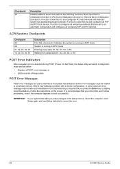
... make changes in ACPI mode. Others may include recommendations for troubleshooting or require that you press the Enter key to diagnostic mode and will either: • Displays a POST error message, or • Emits a series of beep codes POST Error Messages POST error messages tell users what failure the system has detected. System is detected during POST (Power On Self Text), the Setup utility will switch to display recommendations. Follow the instructions on the screen...
... make changes in ACPI mode. Others may include recommendations for troubleshooting or require that you press the Enter key to diagnostic mode and will either: • Displays a POST error message, or • Emits a series of beep codes POST Error Messages POST error messages tell users what failure the system has detected. System is detected during POST (Power On Self Text), the Setup utility will switch to display recommendations. Follow the instructions on the screen...
eMachines EL1852 Service Guide
Page 58
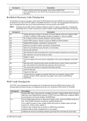
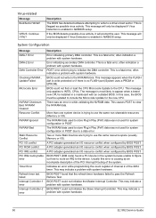
... not used for the new CPU. This causes POST to the NVRAM block. A PCI adapter generated an I /O resource conflict when configured by BIOS POST. Usually this case, the BIOS must be updated to INTEL CPUs. This may indicate a problem with system hardware. Description The BIOS has detected software attempting to write to the device. This is most likely to initialize the DMA controller. BIOS POST (DIM code) found...
... not used for the new CPU. This causes POST to the NVRAM block. A PCI adapter generated an I /O resource conflict when configured by BIOS POST. Usually this case, the BIOS must be updated to INTEL CPUs. This may indicate a problem with system hardware. Description The BIOS has detected software attempting to write to the device. This is most likely to initialize the DMA controller. BIOS POST (DIM code) found...

eMachines EL1852 Service Guide
Page 59
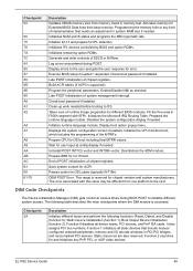
.... Indicates that the CMOS battery needs to malfunction. Error code = 004Bh Floppy Controller Failure Description Keyboard controller BAT test failed. PS/2 mouse support is enabled in the AMIBIOS8 ROM. User needs to unlock the keyboard to reboot the machine. The password entered does not match the password set in initializing legacy Floppy Controller. Error in the setup. EL1852 Service Guide 51 CMOS battery is locked. This error can be replaced. PS/2 keyboard is low. This condition may indicate a problem with system hardware. This message is...
.... Indicates that the CMOS battery needs to malfunction. Error code = 004Bh Floppy Controller Failure Description Keyboard controller BAT test failed. PS/2 mouse support is enabled in the AMIBIOS8 ROM. User needs to unlock the keyboard to reboot the machine. The password entered does not match the password set in initializing legacy Floppy Controller. Error in the setup. EL1852 Service Guide 51 CMOS battery is locked. This error can be replaced. PS/2 keyboard is low. This condition may indicate a problem with system hardware. This message is...
eMachines EL1852 Service Guide
Page 60
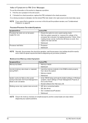
... the processor clock setting should be exactly set to Enabled. Processor/Processor Fan-related Symptoms Symptom/Error Processor fan does not run but the fan still does not work . • IDE drive connection/cables • IDE disk drives • See "Undetermined Problems". • Mainboard NOTE Ensure the memory modules are installed properly and the contact leads are clean before diagnosing any system problems. 52 EL1852 Service Guide If directed to enter power • Enter CMOS Setup and load the default settings. Processor test...
... the processor clock setting should be exactly set to Enabled. Processor/Processor Fan-related Symptoms Symptom/Error Processor fan does not run but the fan still does not work . • IDE drive connection/cables • IDE disk drives • See "Undetermined Problems". • Mainboard NOTE Ensure the memory modules are installed properly and the contact leads are clean before diagnosing any system problems. 52 EL1852 Service Guide If directed to enter power • Enter CMOS Setup and load the default settings. Processor test...
eMachines EL1852 Service Guide
Page 61
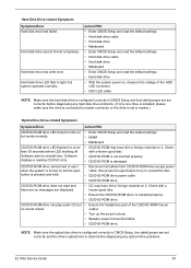
... the HDD LED connector. • HDD LED cable NOTE Make sure the hard disk drive is configured correctly in CMOS Setup, the cable/jumper are set to reinstall disc. Hard disk drive cannot format completely. CD/DVD-ROM drive cannot load or eject when the system is turned on it . CD/DVD-ROM drive LED flashes for more than 30 seconds before diagnosing any hard disk drive problems. (If only one drive is installed, please make sure the drive is connected to unload the disc. • CD/DVD-ROM drive power cable • CD/DVD-ROM drive...
... the HDD LED connector. • HDD LED cable NOTE Make sure the hard disk drive is configured correctly in CMOS Setup, the cable/jumper are set to reinstall disc. Hard disk drive cannot format completely. CD/DVD-ROM drive cannot load or eject when the system is turned on it . CD/DVD-ROM drive LED flashes for more than 30 seconds before diagnosing any hard disk drive problems. (If only one drive is installed, please make sure the drive is connected to unload the disc. • CD/DVD-ROM drive power cable • CD/DVD-ROM drive...
eMachines EL1852 Service Guide
Page 62
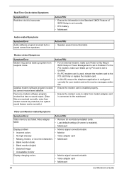
... BIOS Setup is set to the mainboard Video and Monitor-related Symptoms Symptom/Error Video memory test failed.Video adapter failed. voice from modem cannot be produced, but system sound feature works normally.) Action/FRU • For an external modem, make sure Wake up system from modem adapter card is set correctly. • RTC battery • Mainboard Audio-related Symptoms Symptom/Error Audio software program invoked but has no sound comes from speakers. Action/FRU • Speaker power/connection/cable...
... BIOS Setup is set to the mainboard Video and Monitor-related Symptoms Symptom/Error Video memory test failed.Video adapter failed. voice from modem cannot be produced, but system sound feature works normally.) Action/FRU • For an external modem, make sure Wake up system from modem adapter card is set correctly. • RTC battery • Mainboard Audio-related Symptoms Symptom/Error Audio software program invoked but has no sound comes from speakers. Action/FRU • Speaker power/connection/cable...

eMachines EL1852 Service Guide
Page 75
... one pin are numbered. Pins 1 and 2 are placed on bothpins, the jumper is OPEN. Item 15 16 17 18 19 20 Code AUDIO1 SYS_FAN1 ATX12V1 USBLAN1 VGA1 PSKBM2 Component Rear audio jacks (microphone, line-out, and line-in jacks) System fan cable connector 4-pin ATX power connector USB 2.0 and Ethernet ports Monitor port PS/2 keyboard and mouse ports Jumper Setting The section explains how to set jumper for correct configuration of the mainboard. Jumpers withmore than one pin, the jumper...
... one pin are numbered. Pins 1 and 2 are placed on bothpins, the jumper is OPEN. Item 15 16 17 18 19 20 Code AUDIO1 SYS_FAN1 ATX12V1 USBLAN1 VGA1 PSKBM2 Component Rear audio jacks (microphone, line-out, and line-in jacks) System fan cable connector 4-pin ATX power connector USB 2.0 and Ethernet ports Monitor port PS/2 keyboard and mouse ports Jumper Setting The section explains how to set jumper for correct configuration of the mainboard. Jumpers withmore than one pin, the jumper...
eMachines EL1852 Service Guide
Page 96
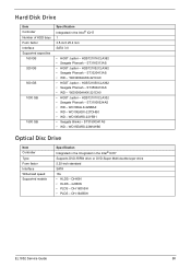
... drive or DVD-Super Multi double-layer drive 5.25-inch standard SATA 16x • HLDS - HDS721016CLA382 • Seagate Pharoah - HDS721032CLA362 • Seagate Pharoah - WD3200AAKX-221CA0 • HGST Jupiter - WD15EARS-22MVWB0 Optical Disc Drive Item Controller Type Form factor Interface Write/read speed Supported models Specification Integrated in the Integrated in the Intel® ICH7 1 3.5-inch 25.4 mm SATA 3.0 • HGST Jupiter - DH-16ABSH EL1852 Service Guide...
... drive or DVD-Super Multi double-layer drive 5.25-inch standard SATA 16x • HLDS - HDS721016CLA382 • Seagate Pharoah - HDS721032CLA362 • Seagate Pharoah - WD3200AAKX-221CA0 • HGST Jupiter - WD15EARS-22MVWB0 Optical Disc Drive Item Controller Type Form factor Interface Write/read speed Supported models Specification Integrated in the Integrated in the Intel® ICH7 1 3.5-inch 25.4 mm SATA 3.0 • HGST Jupiter - DH-16ABSH EL1852 Service Guide...
eMachines EL1852 Service Guide
Page 99
... 4 specifications 89 troubleshooting 54 B beep codes 56 BIOS checkpoints 42 clear CMOS 63 crisis recovery disk 58 recovery 58 specifications 87 update, DOS mode 59 update, Windows mode 60 BIOS version system 10 block diagram 65 boot block beep codes 56 execute 58 boot sequence 12 button optical drive eject 4 C card reader multi-in-1 4 remove 37 specifications 89 checkpoints ACPI runtime 46 DIM 45 overview 42 POST 43 Chipset Features Advanced 13 CMOS clear 63 CMOS Features Index Standard 11 CMOS Setup Utility 7 access 8 navigation keys 9 connectivity options 1 specifications 89 connector LAN...
... 4 specifications 89 troubleshooting 54 B beep codes 56 BIOS checkpoints 42 clear CMOS 63 crisis recovery disk 58 recovery 58 specifications 87 update, DOS mode 59 update, Windows mode 60 BIOS version system 10 block diagram 65 boot block beep codes 56 execute 58 boot sequence 12 button optical drive eject 4 C card reader multi-in-1 4 remove 37 specifications 89 checkpoints ACPI runtime 46 DIM 45 overview 42 POST 43 Chipset Features Advanced 13 CMOS clear 63 CMOS Features Index Standard 11 CMOS Setup Utility 7 access 8 navigation keys 9 connectivity options 1 specifications 89 connector LAN...

eMachines EL1852 Service Guide
Page 100
... 54 monitor port 5 88 N name product 10 O ODD, see optical disc drive 1 operating system 1 optical disc drive configuration 11 remove 29 specifications 88 troubleshooting 53 OS support 1 P panel rear 5 PC Health Status 16 POST, see Power-On Self-Test 43 power ACPI compliance 2 button/indicator 4 specifications 2 power management ACPI mode table 90 specifications 2 Power Management Setup 15 power supply unit 24-pin ATX connector 66 4-pin ATX connector 67 remove 35 specifications 89 troubleshooting 55 Power-On Self-Test beep codes 56 checkpoints 43 error messages 46 processor specifications 86...
... 54 monitor port 5 88 N name product 10 O ODD, see optical disc drive 1 operating system 1 optical disc drive configuration 11 remove 29 specifications 88 troubleshooting 53 OS support 1 P panel rear 5 PC Health Status 16 POST, see Power-On Self-Test 43 power ACPI compliance 2 button/indicator 4 specifications 2 power management ACPI mode table 90 specifications 2 Power Management Setup 15 power supply unit 24-pin ATX connector 66 4-pin ATX connector 67 remove 35 specifications 89 troubleshooting 55 Power-On Self-Test beep codes 56 checkpoints 43 error messages 46 processor specifications 86...
eMachines EL1852 Service Guide
Page 101
... BIOS 87 system chipsets 87 speed processor 10 supervisor password 18 setting 18 system architecture 65 system chipsets 87 system date 11 system dimensions 3 system passwords change 19 remove 19 set 19 system time 11 system views front view 4 system weight 3 T temperature monitoring 16 operating 3 troubleshooting BIOS checkpoints 42 BIOS recovery 58 BIOS update 59 clearing CMOS 63 component failure 52 POST error indicators 46 type processor 10 U undetermined problems 57 USB ports front 4, 5 user password 18 V VGA port 5 video controller 1 troubleshooting 54 W wireless LAN board, remove...
... BIOS 87 system chipsets 87 speed processor 10 supervisor password 18 setting 18 system architecture 65 system chipsets 87 system date 11 system dimensions 3 system passwords change 19 remove 19 set 19 system time 11 system views front view 4 system weight 3 T temperature monitoring 16 operating 3 troubleshooting BIOS checkpoints 42 BIOS recovery 58 BIOS update 59 clearing CMOS 63 component failure 52 POST error indicators 46 type processor 10 U undetermined problems 57 USB ports front 4, 5 user password 18 V VGA port 5 video controller 1 troubleshooting 54 W wireless LAN board, remove...


