
eMachines EL1852 Service Guide
Page 7
... Fan Assembly 26 Removing the Processor 27 Removing the HDD-ODD Bracket 28 Removing the Expansion Boards 33 Removing the Memory Modules 35 Removing the Power Supply Unit 35 Removing the Front I/O and Card Reader Assembly 37 Removing the Mainboard 40 Hardware Diagnostic Procedure 41 System Check Procedures 41 Checkpoints 42 POST...
... Fan Assembly 26 Removing the Processor 27 Removing the HDD-ODD Bracket 28 Removing the Expansion Boards 33 Removing the Memory Modules 35 Removing the Power Supply Unit 35 Removing the Front I/O and Card Reader Assembly 37 Removing the Mainboard 40 Hardware Diagnostic Procedure 41 System Check Procedures 41 Checkpoints 42 POST...
eMachines EL1852 Service Guide
Page 10
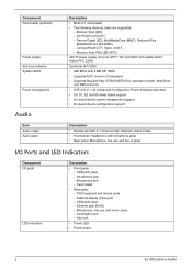
... lock - Secure Digital (SD), MultiMediaCard (MMC), Reduced-Size MultiMediaCard (RS-MMC) - Memory Stick PRO (MS PRO) 220 W power supply unit (non-PFC 110V and 220V with 8 MB SPI ROM • Supports ACPI revision 2.0 standard • Supports Plug and Play...- Ethernet jack (RJ45) - CompactFlash (CF) Types I /O ports LED indicators Description • Front panel - Component Card reader (optional) Power supply Antivirus software System BIOS Power management Audio Item Audio codec Audio jacks Description • Multi-in jacks - USB ports (two) - Card reader • Rear panel ...
... lock - Secure Digital (SD), MultiMediaCard (MMC), Reduced-Size MultiMediaCard (RS-MMC) - Memory Stick PRO (MS PRO) 220 W power supply unit (non-PFC 110V and 220V with 8 MB SPI ROM • Supports ACPI revision 2.0 standard • Supports Plug and Play...- Ethernet jack (RJ45) - CompactFlash (CF) Types I /O ports LED indicators Description • Front panel - Component Card reader (optional) Power supply Antivirus software System BIOS Power management Audio Item Audio codec Audio jacks Description • Multi-in jacks - USB ports (two) - Card reader • Rear panel ...

eMachines EL1852 Service Guide
Page 43
EL1852 Service Guide 35 Disconnect the 4-pin and 24-pin ATX power supply cables from the chassis (2). Gently pull the DIMM upward to release the DIMM (1). 2. Removing the Memory Modules 1. Removing the Power Supply Unit 1. Press the holding clips on both sides of the DIMM slot outward to remove it from the mainboard.
EL1852 Service Guide 35 Disconnect the 4-pin and 24-pin ATX power supply cables from the chassis (2). Gently pull the DIMM upward to release the DIMM (1). 2. Removing the Memory Modules 1. Removing the Power Supply Unit 1. Press the holding clips on both sides of the DIMM slot outward to remove it from the mainboard.
eMachines EL1852 Service Guide
Page 44
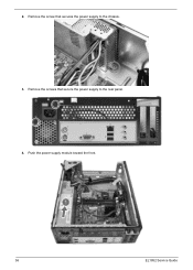
Remove the screw that secure the power supply to the chassis. 3. Push the power supply module toward the front. 36 EL1852 Service Guide Remove the screws that secures the power supply to the rear panel. 4. 2.
Remove the screw that secure the power supply to the chassis. 3. Push the power supply module toward the front. 36 EL1852 Service Guide Remove the screws that secures the power supply to the rear panel. 4. 2.

eMachines EL1852 Service Guide
Page 45
Tilt the power supply module slightly to the right and lift it out of the chassis. Disconnect the power button/LED, front I /O and Card Reader Assembly 1. EL1852 Service Guide 37 Removing the Front I /O and card reader cables from their mainboard connectors. 5.
Tilt the power supply module slightly to the right and lift it out of the chassis. Disconnect the power button/LED, front I /O and Card Reader Assembly 1. EL1852 Service Guide 37 Removing the Front I /O and card reader cables from their mainboard connectors. 5.
eMachines EL1852 Service Guide
Page 60
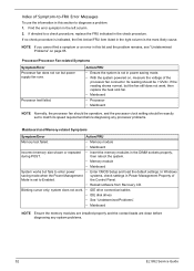
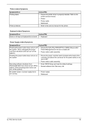
...• Processor • Mainboard NOTE Normally, the processor fan should be operative, and the processor clock setting should be exactly set to enter power • Enter CMOS Setup and load the default settings. NOTE If you cannot find a symptom or an error in this section to diagnose ...connector. Blinking cursor only; Its reading should be +12Vdc. then reboot the system. • Memory module • Mainboard System works but power supply fan runs. Find the error symptom in the left column. 2. the Control Panel. • Reload software from Recovery CD. Index of ...
...• Processor • Mainboard NOTE Normally, the processor fan should be operative, and the processor clock setting should be exactly set to enter power • Enter CMOS Setup and load the default settings. NOTE If you cannot find a symptom or an error in this section to diagnose ...connector. Blinking cursor only; Its reading should be +12Vdc. then reboot the system. • Memory module • Mainboard System works but power supply fan runs. Find the error symptom in the left column. 2. the Control Panel. • Reload software from Recovery CD. Index of ...
eMachines EL1852 Service Guide
Page 63
...Mainboard. • Refer to OFF. • Power switch cable assembly. • Enter CMOS Setup and load the default settings. • Reload software from Recovery CD. • Power supply • Mainboard EL1852 Service Guide 55 No system power, or power supply fan is properly installed. Action/FRU • Ensure... the Soft-off by PWR-BTTN in CMOS Setup (under Power Management) is not set to Instant-off ...
...Mainboard. • Refer to OFF. • Power switch cable assembly. • Enter CMOS Setup and load the default settings. • Reload software from Recovery CD. • Power supply • Mainboard EL1852 Service Guide 55 No system power, or power supply fan is properly installed. Action/FRU • Ensure... the Soft-off by PWR-BTTN in CMOS Setup (under Power Management) is not set to Instant-off ...
eMachines EL1852 Service Guide
Page 65
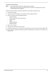
...the failed FRU. Do not isolate non-defective FRU. 1. If the problem does not recur, reconnect the removed devices one at a time). Power on page 41) Follow the procedures below to isolate the failing FRU. Determine if the problem has been resolved. 6. EL1852 Service Guide 57 ...problems are supported by the computer. • Verify that all of the failure is operating correctly. (See "Power System Check" on the computer. 5. Undetermined Problems NOTE • Verify that the power supply being used at the time of the following devices: • Non-Acer devices • Printer, mouse, ...
...the failed FRU. Do not isolate non-defective FRU. 1. If the problem does not recur, reconnect the removed devices one at a time). Power on page 41) Follow the procedures below to isolate the failing FRU. Determine if the problem has been resolved. 6. EL1852 Service Guide 57 ...problems are supported by the computer. • Verify that all of the failure is operating correctly. (See "Power System Check" on the computer. 5. Undetermined Problems NOTE • Verify that the power supply being used at the time of the following devices: • Non-Acer devices • Printer, mouse, ...

eMachines EL1852 Service Guide
Page 79
... LEDs to SYS_FAN. 5. Connect the system cooling fan connector to the F_PANEL. 4. Connect the auxiliary case power supply connector to ATX_POWER. 3. CPU_FAN: CPU Cooling FAN Power Connector Pin Signal Name 1 GND 2 +12V 3 Sense 4 PWM Function System ground Power +12V Sensor PWM EL1852 Service Guide 71 Connecting Case Components After you have installed the motherboard...
... LEDs to SYS_FAN. 5. Connect the system cooling fan connector to the F_PANEL. 4. Connect the auxiliary case power supply connector to ATX_POWER. 3. CPU_FAN: CPU Cooling FAN Power Connector Pin Signal Name 1 GND 2 +12V 3 Sense 4 PWM Function System ground Power +12V Sensor PWM EL1852 Service Guide 71 Connecting Case Components After you have installed the motherboard...

eMachines EL1852 Service Guide
Page 97
... • Realtek ALC662 5.1 Channel High Definition Audio Codec • Front panel: Headphone and microphone jacks • Rear panel: Microphone, line-out, and line-in jacks Power Supply Unit Item Vendor and Model Input Output (max.) Connectors Specification • Delta - supports up to 2 TB • CompactFlash, Type I/II (CF, Type I and II) - supports...
... • Realtek ALC662 5.1 Channel High Definition Audio Codec • Front panel: Headphone and microphone jacks • Rear panel: Microphone, line-out, and line-in jacks Power Supply Unit Item Vendor and Model Input Output (max.) Connectors Specification • Delta - supports up to 2 TB • CompactFlash, Type I/II (CF, Type I and II) - supports...
eMachines EL1852 Service Guide
Page 99
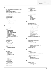
... 2 Advanced BIOS Feature 12 Advanced Configuration Power Interface checkpoints 46 specifications 2 antivirus software 2 asset tag number 10 audio headphone jack 4 microphone jack, rear 5 microphone jack,front 4 specifications 89 troubleshooting 54 B ... reader assembly 37 expansion board 33 front I/O assembly 37 hard disk drive 29 HDD-ODD bracket 28 mainboard 40 memory 35 optical disc drive 29 power supply unit 35 side panel 24 Disassembly Requirements 23 E environmental requirements 3 Ethernet port specifications 89 expansion slots expansion board, remove 33 specifications 1 exploded view 74 ...
... 2 Advanced BIOS Feature 12 Advanced Configuration Power Interface checkpoints 46 specifications 2 antivirus software 2 asset tag number 10 audio headphone jack 4 microphone jack, rear 5 microphone jack,front 4 specifications 89 troubleshooting 54 B ... reader assembly 37 expansion board 33 front I/O assembly 37 hard disk drive 29 HDD-ODD bracket 28 mainboard 40 memory 35 optical disc drive 29 power supply unit 35 side panel 24 Disassembly Requirements 23 E environmental requirements 3 Ethernet port specifications 89 expansion slots expansion board, remove 33 specifications 1 exploded view 74 ...

eMachines EL1852 Service Guide
Page 100
... OS support 1 P panel rear 5 PC Health Status 16 POST, see Power-On Self-Test 43 power ACPI compliance 2 button/indicator 4 specifications 2 power management ACPI mode table 90 specifications 2 Power Management Setup 15 power supply unit 24-pin ATX connector 66 4-pin ATX connector 67 remove 35 specifications ...89 troubleshooting 55 Power-On Self-Test beep codes 56 checkpoints 43 error messages 46 processor specifications 86 troubleshooting 52 PSU, see power supply unit 35 R release date BIOS 10 Return Merchandise Authorization 73 RMA,...
... OS support 1 P panel rear 5 PC Health Status 16 POST, see Power-On Self-Test 43 power ACPI compliance 2 button/indicator 4 specifications 2 power management ACPI mode table 90 specifications 2 Power Management Setup 15 power supply unit 24-pin ATX connector 66 4-pin ATX connector 67 remove 35 specifications ...89 troubleshooting 55 Power-On Self-Test beep codes 56 checkpoints 43 error messages 46 processor specifications 86 troubleshooting 52 PSU, see power supply unit 35 R release date BIOS 10 Return Merchandise Authorization 73 RMA,...
eMachines EL1852 Service Guide
Page 101
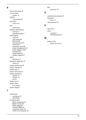
... expansion 5 software specifications antivirus 2 operating system 1 specifications audio 89 card reader 89 Ethernet 89 hard disk drive 88 memory 87 optical disc drive 88 power management 90 power supply unit 89 processor 86 system BIOS 87 system chipsets 87 speed processor 10 supervisor password 18 setting 18 system architecture 65 system chipsets 87...
... expansion 5 software specifications antivirus 2 operating system 1 specifications audio 89 card reader 89 Ethernet 89 hard disk drive 88 memory 87 optical disc drive 88 power management 90 power supply unit 89 processor 86 system BIOS 87 system chipsets 87 speed processor 10 supervisor password 18 setting 18 system architecture 65 system chipsets 87...


