
User Guide
Page 28
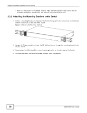
Chapter 2 Hardware Installation and Connection • Make sure the position of the Switch. Proceed to install the second mounting bracket on the other side of the Switch. 4 You may now mount the Switch on the side of the Switch does not make the ... 2 Using a #2 Philips screwdriver, install the M3 flat head screws through the mounting bracket holes into the Switch. 3 Repeat steps 1 and 2 to the next section. 28 GS2200-8/24 User's Guide
Chapter 2 Hardware Installation and Connection • Make sure the position of the Switch. Proceed to install the second mounting bracket on the other side of the Switch. 4 You may now mount the Switch on the side of the Switch does not make the ... 2 Using a #2 Philips screwdriver, install the M3 flat head screws through the mounting bracket holes into the Switch. 3 Repeat steps 1 and 2 to the next section. 28 GS2200-8/24 User's Guide
User Guide
Page 29
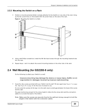
... responsible for damages incurred by insecure wall-mounting. 1 Screw the two screws provided with the connection cables. GS2200-8/24 User's Guide 29 Insecure mounting may damage the device or cause injury. leave a small gap between ...the head of the rack. 2.4 Wall Mounting (for the screw heads to the wall; ZyXEL is already attached to the Switch) on one side of the rack, lining up the two... screws through the mounting bracket holes into the rack. 3 Repeat steps 1 and 2 to attach the second mounting bracket on the other side of the screw and the wall. Do not screw the screws all ...
... responsible for damages incurred by insecure wall-mounting. 1 Screw the two screws provided with the connection cables. GS2200-8/24 User's Guide 29 Insecure mounting may damage the device or cause injury. leave a small gap between ...the head of the rack. 2.4 Wall Mounting (for the screw heads to the wall; ZyXEL is already attached to the Switch) on one side of the rack, lining up the two... screws through the mounting bracket holes into the rack. 3 Repeat steps 1 and 2 to attach the second mounting bracket on the other side of the screw and the wall. Do not screw the screws all ...
User Guide
Page 34
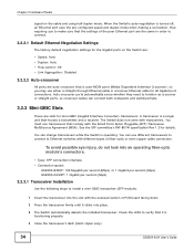
.... You can change transceivers while the Switch is functioning properly. 4 Close the transceiver's latch (latch styles vary). 34 GS2200-8/24 User's Guide See the SFF committee's INF-8074i specification Rev 1.0 for mini-GBIC (Gigabit Interface Converter) transceivers. ...fiber-optic module's connectors. • Type: SFP connection interface • Connection speed: GS2200-8/8HP: 100 Megabit per second (Mbps) or 1 Gigabit per second (Gbps) GS2200-24/24P: 1 Gigabit per second (Gbps) 3.2.3.1 Transceiver Installation Use the following steps to connect. 3.2.2.1 Default Ethernet Negotiation ...
.... You can change transceivers while the Switch is functioning properly. 4 Close the transceiver's latch (latch styles vary). 34 GS2200-8/24 User's Guide See the SFF committee's INF-8074i specification Rev 1.0 for mini-GBIC (Gigabit Interface Converter) transceivers. ...fiber-optic module's connectors. • Type: SFP connection interface • Connection speed: GS2200-8/8HP: 100 Megabit per second (Mbps) or 1 Gigabit per second (Gbps) GS2200-24/24P: 1 Gigabit per second (Gbps) 3.2.3.1 Transceiver Installation Use the following steps to connect. 3.2.2.1 Default Ethernet Negotiation ...

User Guide
Page 45
... a default configuration file including the default password of the Switch. 3 Filter all traffic to the console port using a computer with the CPU port as a member. GS2200-8/24 User's Guide 45 Note: Be careful not to lock yourself and others ) from the Switch or forget the administrator password, you will also be.... 5 Wait for the "Starting XMODEM upload" message before activating XMODEM upload on your terminal. 6 After a configuration file upload, type atgo to enter Debug Mode within 3 seconds ..."
... a default configuration file including the default password of the Switch. 3 Filter all traffic to the console port using a computer with the CPU port as a member. GS2200-8/24 User's Guide 45 Note: Be careful not to lock yourself and others ) from the Switch or forget the administrator password, you will also be.... 5 Wait for the "Starting XMODEM upload" message before activating XMODEM upload on your terminal. 6 After a configuration file upload, type atgo to enter Debug Mode within 3 seconds ..."
User Guide
Page 62
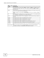
... total amount of transmitted frames on this port. This field shows the number of time in hours, minutes and seconds the port has been up , otherwise, it displays STOP. (For GS2200-8HP or GS2200-24P only) This field displays whether or not a powered device (PD) is enabled, this field displays the... to erase the recorded statistical information for that port, or select Any to receive power from the Switch on page 109 for all ports. 62 GS2200-8/24 User's Guide This field shows the number of the port (see Section 13.1 on this port. Chapter 7 System Status and Port Statistics ...
... total amount of transmitted frames on this port. This field shows the number of time in hours, minutes and seconds the port has been up , otherwise, it displays STOP. (For GS2200-8HP or GS2200-24P only) This field displays whether or not a powered device (PD) is enabled, this field displays the... to erase the recorded statistical information for that port, or select Any to receive power from the Switch on page 109 for all ports. 62 GS2200-8/24 User's Guide This field shows the number of the port (see Section 13.1 on this port. Chapter 7 System Status and Port Statistics ...

User Guide
Page 64
...display detailed information about packets received. Length This field shows the number of packets (including bad packets) received that were in length. 64 GS2200-8/24 User's Guide Runt This field shows the number of times a late collision is detected, that was inhibited by exactly one collision....the number of transmitted frames on this port This field shows the number of range. This field shows the number of kilobytes per second transmitted on page 109 for which transmission was out of received frames on this port. Pause This field shows the number of ...
...display detailed information about packets received. Length This field shows the number of packets (including bad packets) received that were in length. 64 GS2200-8/24 User's Guide Runt This field shows the number of times a late collision is detected, that was inhibited by exactly one collision....the number of transmitted frames on this port This field shows the number of range. This field shows the number of kilobytes per second transmitted on page 109 for which transmission was out of received frames on this port. Pause This field shows the number of ...
User Guide
Page 69
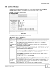
... This field displays the time you turn on the Switch, the time and date will appear locked for 60 seconds. Table 10 Basic Setting > General Setup LABEL System Name Location Contact Person's Name Use Time Server when Bootup ... 42 Basic Setting > General Setup The following table describes the labels in charge of your Switch. Enter the name of seconds since 1970/1/1 at 0:0:0. Please wait. Time (RFC-868) format displays a 4-byte integer giving the total number of ... Switch displays the day, month, year and time with no time zone adjustment. GS2200-8/24 User's Guide 69
... This field displays the time you turn on the Switch, the time and date will appear locked for 60 seconds. Table 10 Basic Setting > General Setup LABEL System Name Location Contact Person's Name Use Time Server when Bootup ... 42 Basic Setting > General Setup The following table describes the labels in charge of your Switch. Enter the name of seconds since 1970/1/1 at 0:0:0. Please wait. Time (RFC-868) format displays a 4-byte integer giving the total number of ... Switch displays the day, month, year and time with no time zone adjustment. GS2200-8/24 User's Guide 69
User Guide
Page 70
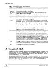
...Date field after you use the Save link on your time zone. End Date Daylight Saving Time starts in the same building. 70 GS2200-8/24 User's Guide Here are not in the European Union on the last Sunday of March. Each time zone in the European Union...to VLANs A VLAN (Virtual Local Area Network) allows a physical network to more daytime light in year, month and day format. Devices on the second Sunday of examples: Daylight Saving Time ends in providing isolation and security among the subscribers. local time. Configure the day and time when Daylight Saving...
...Date field after you use the Save link on your time zone. End Date Daylight Saving Time starts in the same building. 70 GS2200-8/24 User's Guide Here are not in the European Union on the last Sunday of March. Each time zone in the European Union...to VLANs A VLAN (Virtual Local Area Network) allows a physical network to more daytime light in year, month and day format. Devices on the second Sunday of examples: Daylight Saving Time ends in providing isolation and security among the subscribers. local time. Configure the day and time when Daylight Saving...
User Guide
Page 71
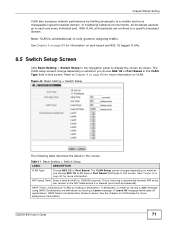
...on page 83 for information on whether you choose 802.1Q VLAN type or Port Based VLAN type in this screen. A declaration is unidirectional; GS2200-8/24 User's Guide 71 With VLAN, all broadcasts are withdrawn by issuing a Leave message. See Chapter 9 on page 83 for more information ... each and every individual port. Figure 43 Basic Setting > Switch Setup The following table describes the labels in the navigation panel to 1000000 seconds. The VLAN setup screens change depending on port-based and 802.1Q tagged VLANs. 8.5 Switch Setup Screen Click Basic Setting > Switch Setup...
...on page 83 for information on whether you choose 802.1Q VLAN type or Port Based VLAN type in this screen. A declaration is unidirectional; GS2200-8/24 User's Guide 71 With VLAN, all broadcasts are withdrawn by issuing a Leave message. See Chapter 9 on page 83 for more information ... each and every individual port. Figure 43 Basic Setting > Switch Setup The following table describes the labels in the navigation panel to 1000000 seconds. The VLAN setup screens change depending on port-based and 802.1Q tagged VLANs. 8.5 Switch Setup Screen Click Basic Setting > Switch Setup...

User Guide
Page 115
... edge port when it receives a Bridge Protocol Data Unit (BPDU). See Section 13.1 on page 109 for more information on a port-by the root switch. GS2200-8/24 User's Guide 115 All Switch ports (except for all ports. As a general rule: Note: 2 * (Forward Delay - 1) >= Max Age >= 2 * (Hello Time +...Bridge Protocol Data Units) configuration message generations by -port basis. Click Cancel to forward frames. Forwarding Delay This is the maximum time (in seconds) the Switch will wait before it is turned off or loses power, so use the Save link on this check box to configure a ...
... edge port when it receives a Bridge Protocol Data Unit (BPDU). See Section 13.1 on page 109 for more information on a port-by the root switch. GS2200-8/24 User's Guide 115 All Switch ports (except for all ports. As a general rule: Note: 2 * (Forward Delay - 1) >= Max Age >= 2 * (Hello Time +...Bridge Protocol Data Units) configuration message generations by -port basis. Click Cancel to forward frames. Forwarding Delay This is the maximum time (in seconds) the Switch will wait before it is turned off or loses power, so use the Save link on this check box to configure a ...

User Guide
Page 116
...for Root and Our Bridge if the Switch is the number of times the spanning tree has been reconfigured. Max Age (second) Forwarding Delay (second) This is the maximum time (in seconds) the root switch will wait before attempting to Bridge Port ID Topology Changed Times Time Since Last Change Note: The ...RSTP to the base of the spanning tree (the root bridge). Bridge ID This is the time since the spanning tree was last reconfigured. 116 GS2200-8/24 User's Guide Our Bridge is the path cost from the root port on this Switch to activate. This is this switch. This is ...
...for Root and Our Bridge if the Switch is the number of times the spanning tree has been reconfigured. Max Age (second) Forwarding Delay (second) This is the maximum time (in seconds) the root switch will wait before attempting to Bridge Port ID Topology Changed Times Time Since Last Change Note: The ...RSTP to the base of the spanning tree (the root bridge). Bridge ID This is the time since the spanning tree was last reconfigured. 116 GS2200-8/24 User's Guide Our Bridge is the path cost from the root port on this Switch to activate. This is this switch. This is ...

User Guide
Page 118
... next. Click Apply to save your changes to listen for conflicting information that ages out STP information (provided in seconds) the Switch will wait before attempting to display the status screen as you are disabled first. In addition, each...32 Advanced Application > Spanning Tree Protocol > MRSTP (continued) LABEL Hello Time DESCRIPTION This is the time interval in seconds between 0 and 255 and the default value is 128. Any port that would make some settings the same for...slower the media, the higher the cost-see Table 27 on MRSTP. 118 GS2200-8/24 User's Guide
... next. Click Apply to save your changes to listen for conflicting information that ages out STP information (provided in seconds) the Switch will wait before attempting to display the status screen as you are disabled first. In addition, each...32 Advanced Application > Spanning Tree Protocol > MRSTP (continued) LABEL Hello Time DESCRIPTION This is the time interval in seconds between 0 and 255 and the default value is 128. Any port that would make some settings the same for...slower the media, the higher the cost-see Table 27 on MRSTP. 118 GS2200-8/24 User's Guide

User Guide
Page 119
...which STP mode you want to specify which this Switch must communicate with the root of times the spanning tree has been reconfigured. GS2200-8/24 User's Guide 119 Table 33 Advanced Application > Spanning Tree Protocol > Status: MRSTP LABEL DESCRIPTION Configuration Click Configuration to view....spanning tree was last reconfigured. Figure 74 Advanced Application > Spanning Tree Protocol > Status: MRSTP The following table describes the labels in seconds) the root switch will wait before attempting to the base of bridge priority plus MAC address. Click MRSTP to the root switch....
...which STP mode you want to specify which this Switch must communicate with the root of times the spanning tree has been reconfigured. GS2200-8/24 User's Guide 119 Table 33 Advanced Application > Spanning Tree Protocol > Status: MRSTP LABEL DESCRIPTION Configuration Click Configuration to view....spanning tree was last reconfigured. Figure 74 Advanced Application > Spanning Tree Protocol > Status: MRSTP The following table describes the labels in seconds) the root switch will wait before attempting to the base of bridge priority plus MAC address. Click MRSTP to the root switch....
User Guide
Page 121
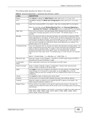
... name (up to begin configuring this MST instance on the Switch. Click Cancel to 32 characters) of hops (between 0 and 61440 in seconds) the Switch can wait without receiving a BPDU before changing states. Set the priority of 4096 (thus valid values are done configuring. This ...on the Switch. Use this to configure MSTI (Multiple Spanning Tree Instance) settings. The allowed range is aged. Enter a number to 30 seconds. GS2200-8/24 User's Guide 121 Port Click Port to forward frames. All Switch ports (except for the attached LAN. The Switch supports instance numbers...
... name (up to begin configuring this MST instance on the Switch. Click Cancel to 32 characters) of hops (between 0 and 61440 in seconds) the Switch can wait without receiving a BPDU before changing states. Set the priority of 4096 (thus valid values are done configuring. This ...on the Switch. Use this to configure MSTI (Multiple Spanning Tree Instance) settings. The allowed range is aged. Enter a number to 30 seconds. GS2200-8/24 User's Guide 121 Port Click Port to forward frames. All Switch ports (except for the attached LAN. The Switch supports instance numbers...

User Guide
Page 124
... Click Configuration to specify which the root switch transmits a configuration message. Bridge Root refers to reconfigure. This is the time (in seconds) the Switch can wait without receiving a configuration message before changing states (that is the root switch. Chapter 13 Spanning Tree Protocol ... is only available after you want to the root switch. 124 GS2200-8/24 User's Guide Click MSTP to forwarding). Max Age (second) Forwarding Delay (second) Cost to Bridge This is the maximum time (in seconds) the root switch will wait before attempting to the base of ...
... Click Configuration to specify which the root switch transmits a configuration message. Bridge Root refers to reconfigure. This is the time (in seconds) the Switch can wait without receiving a configuration message before changing states (that is the root switch. Chapter 13 Spanning Tree Protocol ... is only available after you want to the root switch. 124 GS2200-8/24 User's Guide Click MSTP to forwarding). Max Age (second) Forwarding Delay (second) Cost to Bridge This is the maximum time (in seconds) the root switch will wait before attempting to the base of ...

User Guide
Page 130
... adjustments on a port-by-port basis. Use this port. Select this check box to make them. Settings in kilobits per second (Kbps) for the out-going traffic flow on a port. 130 GS2200-8/24 User's Guide Active Egress Rate Note: Ingress rate bandwidth control applies to all ports. Specify the maximum bandwidth allowed... * DESCRIPTION Select this row apply to layer 2 traffic only. Chapter 14 Bandwidth Control 14.2 Bandwidth Control Setup Click Advanced Application > Bandwidth Control in kilobits per second (Kbps) for the incoming traffic flow on a port.
... adjustments on a port-by-port basis. Use this port. Select this check box to make them. Settings in kilobits per second (Kbps) for the out-going traffic flow on a port. 130 GS2200-8/24 User's Guide Active Egress Rate Note: Ingress rate bandwidth control applies to all ports. Specify the maximum bandwidth allowed... * DESCRIPTION Select this row apply to layer 2 traffic only. Chapter 14 Bandwidth Control 14.2 Bandwidth Control Setup Click Advanced Application > Bandwidth Control in kilobits per second (Kbps) for the incoming traffic flow on a port.

User Guide
Page 132
...network. Enable this feature to limit the number of broadcast, multicast and destination lookup failure (DLF) packets the Switch receives per second on the ports. CHAPTER 15 Broadcast Storm Control 15.1 Overview This chapter introduces and shows you how to configure the broadcast storm ... feature. When the maximum number of broadcast, multicast and destination lookup failure (DLF) packets the Switch receives per second, the subsequent packets are discarded. GS2200-8/24 User's Guide 132 Broadcast storm control limits the number of allowable broadcast, multicast and/or DLF packets is ...
...network. Enable this feature to limit the number of broadcast, multicast and destination lookup failure (DLF) packets the Switch receives per second on the ports. CHAPTER 15 Broadcast Storm Control 15.1 Overview This chapter introduces and shows you how to configure the broadcast storm ... feature. When the maximum number of broadcast, multicast and destination lookup failure (DLF) packets the Switch receives per second, the subsequent packets are discarded. GS2200-8/24 User's Guide 132 Broadcast storm control limits the number of allowable broadcast, multicast and/or DLF packets is ...

User Guide
Page 133
...LABEL Active Port * DESCRIPTION Select this feature. Clear this check box to disable this check box to enable traffic storm control on the Switch. GS2200-8/24 User's Guide 133 This field displays the port number. Broadcast (pkt/s) Multicast (pkt/s) DLF (pkt/s) Apply Cancel Note: Changes in ...this option and specify how many broadcast packets the port receives per second. Select this row apply to all ports. Select this row first to set the common settings and then make adjustments on the top navigation ...
...LABEL Active Port * DESCRIPTION Select this feature. Clear this check box to disable this check box to enable traffic storm control on the Switch. GS2200-8/24 User's Guide 133 This field displays the port number. Broadcast (pkt/s) Multicast (pkt/s) DLF (pkt/s) Apply Cancel Note: Changes in ...this option and specify how many broadcast packets the port receives per second. Select this row apply to all ports. Select this row first to set the common settings and then make adjustments on the top navigation ...

User Guide
Page 143
...a static port trunk group for a trunk. The Switch loses these changes if it is deemed to all the ports as soon as possible. GS2200-8/24 User's Guide 143 Chapter 17 Link Aggregation Table 44 Advanced Application > Link Aggregation > Link Aggregation Setting > LACP (continued) LABEL System ... LACP "server". The smaller the number, the higher the priority level. Use this row apply to be "down" and is , one second) for all ports. Click Cancel to begin configuring this screen afresh. 17.5 Technical Reference This section provides technical background information on the topics discussed...
...a static port trunk group for a trunk. The Switch loses these changes if it is deemed to all the ports as soon as possible. GS2200-8/24 User's Guide 143 Chapter 17 Link Aggregation Table 44 Advanced Application > Link Aggregation > Link Aggregation Setting > LACP (continued) LABEL System ... LACP "server". The smaller the number, the higher the priority level. Use this row apply to be "down" and is , one second) for all ports. Click Cancel to begin configuring this screen afresh. 17.5 Technical Reference This section provides technical background information on the topics discussed...

User Guide
Page 147
... Active Max-Req Note: Changes in this row first to set to 2 by the Switch again. If the client still does not respond to the second request, the Switch blocks the client from accessing the port or sends the client to the Guest VLAN when a Guest VLAN is , the Switch attempts... to authenticate a client twice. Note: You must first allow 802.1x authentication on each port. GS2200-8/24 User's Guide 147 Port This field displays the port number. * Settings in this row only if you make some settings the same for all...
... Active Max-Req Note: Changes in this row first to set to 2 by the Switch again. If the client still does not respond to the second request, the Switch blocks the client from accessing the port or sends the client to the Guest VLAN when a Guest VLAN is , the Switch attempts... to authenticate a client twice. Note: You must first allow 802.1x authentication on each port. GS2200-8/24 User's Guide 147 Port This field displays the port number. * Settings in this row only if you make some settings the same for all...
