

User Guide
Page 3
...) ...7 Chapter 2 Hardware Description and Connection 9 2.1 Rear Panel ...9 2.1.1 Rear Panel Power Connection 9 2.2 Front Panel ...9 2.2.1 RJ-45 Auto-negotiating Ports 10 2.2.2 IEEE 802.3az EEE ...10 2.2.3 SFP Slots (GS1100-24 Only 10 2.2.4 Front Panel Connections ...12 2.2.5 Front Panel LEDs ...12 2.3 Hardware Installation ...14 2.3.1 Wall Mounting ...14 2.3.2 Rack Mounting ...15 2.3.3 Mounting the Switch on a Rack 16 Chapter 3 Troubleshooting...19 3.1 Improper Network Cabling and Topology 20 Appendix A Legal Information...21 Index ...23 GS1100 Series User's Guide 3
...) ...7 Chapter 2 Hardware Description and Connection 9 2.1 Rear Panel ...9 2.1.1 Rear Panel Power Connection 9 2.2 Front Panel ...9 2.2.1 RJ-45 Auto-negotiating Ports 10 2.2.2 IEEE 802.3az EEE ...10 2.2.3 SFP Slots (GS1100-24 Only 10 2.2.4 Front Panel Connections ...12 2.2.5 Front Panel LEDs ...12 2.3 Hardware Installation ...14 2.3.1 Wall Mounting ...14 2.3.2 Rack Mounting ...15 2.3.3 Mounting the Switch on a Rack 16 Chapter 3 Troubleshooting...19 3.1 Improper Network Cabling and Topology 20 Appendix A Legal Information...21 Index ...23 GS1100 Series User's Guide 3

User Guide
Page 5
... 802.3az ON/OFF button One power ON/OFF switch GS1100-24 GS1100-24E The GS1100-8HP has four GbE PoE ports that offers low latency for small businesses. Use SFP transceivers in these slots for uplink connection. The Switch is a store-and-forward device that can be used to Know Your Switch 1.1 Introduction This chapter describes the key features, benefits and applications of your Switch. GS1100 Series User's Guide 5
... 802.3az ON/OFF button One power ON/OFF switch GS1100-24 GS1100-24E The GS1100-8HP has four GbE PoE ports that offers low latency for small businesses. Use SFP transceivers in these slots for uplink connection. The Switch is a store-and-forward device that can be used to Know Your Switch 1.1 Introduction This chapter describes the key features, benefits and applications of your Switch. GS1100 Series User's Guide 5

User Guide
Page 6
... and IEEE 802.3at PoE standards (only GS1100-8HP) • Full wire speed forwarding rate. • Supports 802.1p CoS. • Embedded 8K MAC address table providing 8000 MAC addresses entries. 1.3 Applications This section provides two network topology examples in which the Switch is used. 6 GS1100 Series User's Guide Chapter 1 Getting to Know Your Switch Figure 1 Front Panel GS1100-8HP GS1100-16 GS1100-24 GS1100-24E 1.2 Features The following are the essential...
... and IEEE 802.3at PoE standards (only GS1100-8HP) • Full wire speed forwarding rate. • Supports 802.1p CoS. • Embedded 8K MAC address table providing 8000 MAC addresses entries. 1.3 Applications This section provides two network topology examples in which the Switch is used. 6 GS1100 Series User's Guide Chapter 1 Getting to Know Your Switch Figure 1 Front Panel GS1100-8HP GS1100-16 GS1100-24 GS1100-24E 1.2 Features The following are the essential...
User Guide
Page 7
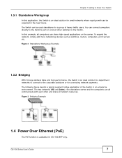
... with each other switches to the Switch. GS1100 Series User's Guide 7 The following figure depicts a typical segment bridge application of heavy traffic users. In this application, the Switch is an ideal solution for a group of the Switch in the near future. To expand the network, simply add more networking devices such as switches, routers, computers, print servers etc. You can connect computers directly to the Switch's port or connect other and share...
... with each other switches to the Switch. GS1100 Series User's Guide 7 The following figure depicts a typical segment bridge application of heavy traffic users. In this application, the Switch is an ideal solution for a group of the Switch in the near future. To expand the network, simply add more networking devices such as switches, routers, computers, print servers etc. You can connect computers directly to the Switch's port or connect other and share...
User Guide
Page 8
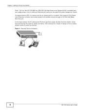
... 4 Powered Device Examples 8 GS1100 Series User's Guide Aside from the Switch. In the figure below, the IP camera and IP phone get their power directly from minimizing the need for cables and wires, PoE removes the hassle of up to the total PoE power budget per Ethernet port and up devices. Chapter 1 Getting to Know Your Switch Ports 1 to 4 on the GS1100-8HP are IEEE 802.3at High Power over Ethernet) so that supports PoE (Power over Ethernet...
... 4 Powered Device Examples 8 GS1100 Series User's Guide Aside from the Switch. In the figure below, the IP camera and IP phone get their power directly from minimizing the need for cables and wires, PoE removes the hassle of up to the total PoE power budget per Ethernet port and up devices. Chapter 1 Getting to Know Your Switch Ports 1 to 4 on the GS1100-8HP are IEEE 802.3at High Power over Ethernet) so that supports PoE (Power over Ethernet...

User Guide
Page 9
GS1100 Series User's Guide 9 For the GS1100-8HP, GS1100-16 and GS1100-24E, use the POWER ON/OFF switch to the appropriate power source. Figure 5 Rear Panel GS1100-8HP GS1100-16 GS1100-24 GS1100-24E 2.1.1 Rear Panel Power Connection Connect one end of the supplied power cord or power adaptor to the power receptacle on the back of the Switch and the other end to have the Switch power on or off. 2.2 Front Panel The front panel of...
GS1100 Series User's Guide 9 For the GS1100-8HP, GS1100-16 and GS1100-24E, use the POWER ON/OFF switch to the appropriate power source. Figure 5 Rear Panel GS1100-8HP GS1100-16 GS1100-24 GS1100-24E 2.1.1 Rear Panel Power Connection Connect one end of the supplied power cord or power adaptor to the power receptacle on the back of the Switch and the other end to have the Switch power on or off. 2.2 Front Panel The front panel of...

User Guide
Page 10
... Installation Use the following steps to be impacted due to the latency from the additional time required for details. Refer to save power. An EEE-enabled device initiates Low Power Idle (LPI) signals to negotiate and wake up the remote device when there is data to install a SFP module. 1 Insert the transceiver into power saving mode and switch off part of PCB board facing down. 10 GS1100 Series User's Guide Disable...
... Installation Use the following steps to be impacted due to the latency from the additional time required for details. Refer to save power. An EEE-enabled device initiates Low Power Idle (LPI) signals to negotiate and wake up the remote device when there is data to install a SFP module. 1 Insert the transceiver into power saving mode and switch off part of PCB board facing down. 10 GS1100 Series User's Guide Disable...

User Guide
Page 11
... vary). 5 Connect the fiber optic cables to remove a SFP module. 1 Remove the fiber optic cables from the transceiver. 2 Open the transceiver's latch (latch styles vary). 3 Pull the transceiver out of the slot. Figure 6 Transceiver Installation Example Figure 7 Connecting the Fiber Optic Cables 2.2.3.2 Transceiver Removal Use the following steps to the transceiver. Check the LEDs to verify that it clicks into place. 3 The Switch automatically detects the installed transceiver.
... vary). 5 Connect the fiber optic cables to remove a SFP module. 1 Remove the fiber optic cables from the transceiver. 2 Open the transceiver's latch (latch styles vary). 3 Pull the transceiver out of the slot. Figure 6 Transceiver Installation Example Figure 7 Connecting the Fiber Optic Cables 2.2.3.2 Transceiver Removal Use the following steps to the transceiver. Check the LEDs to verify that it clicks into place. 3 The Switch automatically detects the installed transceiver.

User Guide
Page 12
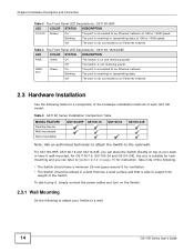
... types of the LEDs. 12 GS1100 Series User's Guide Table 2 Network Cable Types SPEED NETWORK CABLE TYPE 10 Mbps Category 3, 4 or 5 UTP/STP 100 Mbps Category 5 UTP/STP 1000 Mbps Category 5e, 6 UTP/STP You can use either crossover or straight-through cables for all the ports. 2.2.5 Front Panel LEDs The LED Indicators give real-time information about the status of the Switch. Chapter 2 Hardware Description and Connection Figure 10 Transceiver Removal Example 2.2.4 Front Panel Connections...
... types of the LEDs. 12 GS1100 Series User's Guide Table 2 Network Cable Types SPEED NETWORK CABLE TYPE 10 Mbps Category 3, 4 or 5 UTP/STP 100 Mbps Category 5 UTP/STP 1000 Mbps Category 5e, 6 UTP/STP You can use either crossover or straight-through cables for all the ports. 2.2.5 Front Panel LEDs The LED Indicators give real-time information about the status of the Switch. Chapter 2 Hardware Description and Connection Figure 10 Transceiver Removal Example 2.2.4 Front Panel Connections...

User Guide
Page 13
Figure 11 Front Panel LEDs GS1100-8HP GS1100-16 GS1100-24 GS1100-24E Chapter 2 Hardware Description and Connection The following table describes the LEDs. Blinking The port is not receiving power. GS1100 Series User's Guide 13 PoE MAX Red On Power supplied to an Ethernet network at 1000M speed. Table 3 The Front Panel LED Descriptions: GS1100-8HP LED COLOR STATUS DESCRIPTION PWR Green On The Switch is connected to the PoE port(s) reachs the power budget limit or exceeds the total...
Figure 11 Front Panel LEDs GS1100-8HP GS1100-16 GS1100-24 GS1100-24E Chapter 2 Hardware Description and Connection The following table describes the LEDs. Blinking The port is not receiving power. GS1100 Series User's Guide 13 PoE MAX Red On Power supplied to an Ethernet network at 1000M speed. Table 3 The Front Panel LED Descriptions: GS1100-8HP LED COLOR STATUS DESCRIPTION PWR Green On The Switch is connected to the PoE port(s) reachs the power budget limit or exceeds the total...
User Guide
Page 14
... LED Descriptions: GS1100-16/24/24E LED COLOR STATUS DESCRIPTION PWR Green On The Switch is receiving or transmitting data. To start using it, simply connect the power cables and turn on and receiving power. Chapter 2 Hardware Description and Connection Table 3 The Front Panel LED Descriptions: GS1100-8HP LED COLOR STATUS DESCRIPTION 10/100 Amber On The port is not connected to an Ethernet network. 2.3 Hardware Installation See the following table for instruction. Off The port...
... LED Descriptions: GS1100-16/24/24E LED COLOR STATUS DESCRIPTION PWR Green On The Switch is receiving or transmitting data. To start using it, simply connect the power cables and turn on and receiving power. Chapter 2 Hardware Description and Connection Table 3 The Front Panel LED Descriptions: GS1100-8HP LED COLOR STATUS DESCRIPTION 10/100 Amber On The port is not connected to an Ethernet network. 2.3 Hardware Installation See the following table for instruction. Off The port...
User Guide
Page 15
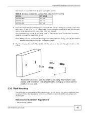
... between the centers of the Switch with the connection cables. 2 Align the holes on the wall. Hang the Switch on a standard EIA rack using a rackmounting kit. Rack-mounted Installation Requirements • Two mounting brackets. Do not screw the screws all the way in to place the screws. GS1100 Series User's Guide 15 Note: Make sure the screws are securely fixed to the wall and...
... between the centers of the Switch with the connection cables. 2 Align the holes on the wall. Hang the Switch on a standard EIA rack using a rackmounting kit. Rack-mounted Installation Requirements • Two mounting brackets. Do not screw the screws all the way in to place the screws. GS1100 Series User's Guide 15 Note: Make sure the screws are securely fixed to the wall and...

User Guide
Page 16
... the Switch. 3 Repeat steps 1 and 2 to install the second mounting bracket on the other side of all necessary precautions to the Switch) on one side of the Switch, lining up the two screw holes on the bracket with the screw holes on a rack. Proceed to the next section. 2.3.3 Mounting the Switch on the side of the rack. 16 GS1100 Series User's Guide Precautions • Make...
... the Switch. 3 Repeat steps 1 and 2 to install the second mounting bracket on the other side of all necessary precautions to the Switch) on one side of the Switch, lining up the two screw holes on the bracket with the screw holes on a rack. Proceed to the next section. 2.3.3 Mounting the Switch on the side of the rack. 16 GS1100 Series User's Guide Precautions • Make...

User Guide
Page 17
GS1100 Series User's Guide 17 Chapter 2 Hardware Description and Connection Figure 14 Mounting the Switch on a Rack (GS1100-16 and GS1100-24E) Figure 15 Mounting the Switch on a Rack (GS1100-24) 2 Using a #2 Philips screwdriver, install the M5 flat head screws through the mounting bracket holes into the rack. 3 Repeat steps 1 and 2 to attach the second mounting bracket on the other side of the rack.
GS1100 Series User's Guide 17 Chapter 2 Hardware Description and Connection Figure 14 Mounting the Switch on a Rack (GS1100-16 and GS1100-24E) Figure 15 Mounting the Switch on a Rack (GS1100-24) 2 Using a #2 Philips screwdriver, install the M5 flat head screws through the mounting bracket holes into the rack. 3 Repeat steps 1 and 2 to attach the second mounting bracket on the other side of the rack.
User Guide
Page 19
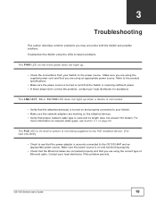
... 3 Troubleshooting This section describes common problems you are using the correct type of Ethernet cable. The PoE LED is off and/or power is not being supplied to my PoE-enabled device. (For GS1100-8HP) • Check to see Section 3.1 on and that the Switch is turned on page 20. Refer to the product specifications. • Make sure the power source is receiving sufficient power. • If these steps fail to the GS1100...
... 3 Troubleshooting This section describes common problems you are using the correct type of Ethernet cable. The PoE LED is off and/or power is not being supplied to my PoE-enabled device. (For GS1100-8HP) • Check to see Section 3.1 on and that the Switch is turned on page 20. Refer to the product specifications. • Make sure the power source is receiving sufficient power. • If these steps fail to the GS1100...
User Guide
Page 20
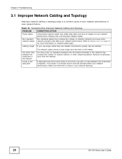
Figure 16 Troubleshooting Improper Network Cabling and Topology PROBLEM Faulty cables Non-standard network cables Cabling Length CORRECTIVE ACTION Using faulty network cables may be longer than one path or route between two networked computers. Make sure there are needed, transmission quality may affect data rates and have an impact on network cable types. Replace with new standard network cables. Chapter 3 Troubleshooting 3.1 Improper Network Cabling and Topology Improper network cabling or topology setup is more information on your network performance...
Figure 16 Troubleshooting Improper Network Cabling and Topology PROBLEM Faulty cables Non-standard network cables Cabling Length CORRECTIVE ACTION Using faulty network cables may be longer than one path or route between two networked computers. Make sure there are needed, transmission quality may affect data rates and have an impact on network cable types. Replace with new standard network cables. Chapter 3 Troubleshooting 3.1 Improper Network Cabling and Topology Improper network cabling or topology setup is more information on your network performance...

User Guide
Page 21
... could void the user's authority to Part 15 of God, or subjected to radio communications. GS1100 Series User's Guide 21 All rights reserved. FCC Warning This device has been tested and found to comply with your vendor and/or the authorized ZyXEL local distributor for a Class A digital switch, pursuant to operate the equipment. In a domestic environment this product's documentation and certifications. The...
... could void the user's authority to Part 15 of God, or subjected to radio communications. GS1100 Series User's Guide 21 All rights reserved. FCC Warning This device has been tested and found to comply with your vendor and/or the authorized ZyXEL local distributor for a Class A digital switch, pursuant to operate the equipment. In a domestic environment this product's documentation and certifications. The...

User Guide
Page 22
... to the correct ports. • Place connecting cables carefully so that no event be treated separately. 22 GS1100 Series User's Guide You may harm your device to rest on the power adaptor or cord and do NOT place the product where anyone can expose you bought the device at www.us.zyxel.com for a particular use this product near water, for example, in no one...
... to the correct ports. • Place connecting cables carefully so that no event be treated separately. 22 GS1100 Series User's Guide You may harm your device to rest on the power adaptor or cord and do NOT place the product where anyone can expose you bought the device at www.us.zyxel.com for a particular use this product near water, for example, in no one...

User Guide
Page 23
... Efficient Ethernet 10 F Faulty cables 20 FCC interference statement 21 Front Panel 9 GS1100 Series User's Guide Index Index Front Panel Connections 12 H High Power over Ethernet 8 I IEEE 802.3at 8 IEEE 802.3az 10 installation precautions 16 transceivers 10 L LED Descriptions LK/ACT 14 PWR 13, 14 Low Power Idle 10 LPI signal 10 M mounting brackets 16 N network cable crossover 12 straight-through 12 Network Cable Types 12 Non-standard network cables 20...
... Efficient Ethernet 10 F Faulty cables 20 FCC interference statement 21 Front Panel 9 GS1100 Series User's Guide Index Index Front Panel Connections 12 H High Power over Ethernet 8 I IEEE 802.3at 8 IEEE 802.3az 10 installation precautions 16 transceivers 10 L LED Descriptions LK/ACT 14 PWR 13, 14 Low Power Idle 10 LPI signal 10 M mounting brackets 16 N network cable crossover 12 straight-through 12 Network Cable Types 12 Non-standard network cables 20...

User Guide
Page 24
Index P PD 8 PoE 8 power supplying 8 Power over Ethernet 8 power saving 10 powered device 8 product registration 22 R rack mounting 15 Rear Panel 9 Rear Panel Power Connection 9 registration product 22 S safety warnings 22 Small Form-factor Pluggable (SFP) 10 Standalone Workgroup 7 T transceiver MultiSource Agreement (MSA) 10 transceivers 10 installation 10 removal 11 Troubleshooting Improper Network Cabling and Topology 20 W wall mounting 14 warranty 21 note 22 24 GS1100 Series User's Guide
Index P PD 8 PoE 8 power supplying 8 Power over Ethernet 8 power saving 10 powered device 8 product registration 22 R rack mounting 15 Rear Panel 9 Rear Panel Power Connection 9 registration product 22 S safety warnings 22 Small Form-factor Pluggable (SFP) 10 Standalone Workgroup 7 T transceiver MultiSource Agreement (MSA) 10 transceivers 10 installation 10 removal 11 Troubleshooting Improper Network Cabling and Topology 20 W wall mounting 14 warranty 21 note 22 24 GS1100 Series User's Guide


