

User Guide
Page 12
... of the Web Configurator 50 4.8 Help ...51 Chapter 5 Initial Setup Example...53 5.1 Overview ...53 5.1.1 Creating a VLAN ...53 5.1.2 Setting Port VID ...55 5.1.3 Configuring Switch Management IP Address 56 Chapter 6 Tutorials ...59 6.1 How to Use DHCP Relay on the Switch 59 6.1.1 DHCP Relay Tutorial Introduction 59 6.1.2 Creating a VLAN ...60 6.1.3 Configuring DHCP Relay 62 6.1.4 Troubleshooting ...63 Chapter 7 System Status and Port Statistics 65 7.1 Overview ...65 7.2 Port Status Summary ...65 7.2.1 Status: Port Details 67 Chapter 8 Basic Setting ...71 12 ES-2024 Series User's Guide
... of the Web Configurator 50 4.8 Help ...51 Chapter 5 Initial Setup Example...53 5.1 Overview ...53 5.1.1 Creating a VLAN ...53 5.1.2 Setting Port VID ...55 5.1.3 Configuring Switch Management IP Address 56 Chapter 6 Tutorials ...59 6.1 How to Use DHCP Relay on the Switch 59 6.1.1 DHCP Relay Tutorial Introduction 59 6.1.2 Creating a VLAN ...60 6.1.3 Configuring DHCP Relay 62 6.1.4 Troubleshooting ...63 Chapter 7 System Status and Port Statistics 65 7.1 Overview ...65 7.2 Port Status Summary ...65 7.2.1 Status: Port Details 67 Chapter 8 Basic Setting ...71 12 ES-2024 Series User's Guide

User Guide
Page 35
... the Gigabit ports. ES-2024 Series User's Guide 35 You can use transceivers that if a mini-GBIC port and the corresponding Gigabit port are connected at the same time, the Gigabit port will be disabled. This means that comply with different types of Gigabit Ethernet/mini-GBIC ports. The Switch does not come with a straightthrough or crossover Ethernet cable. 3.1.2.1 Default Ethernet Settings The factory default negotiation settings for the Ethernet ports on the Switch are: • Speed: Auto...
... the Gigabit ports. ES-2024 Series User's Guide 35 You can use transceivers that if a mini-GBIC port and the corresponding Gigabit port are connected at the same time, the Gigabit port will be disabled. This means that comply with different types of Gigabit Ethernet/mini-GBIC ports. The Switch does not come with a straightthrough or crossover Ethernet cable. 3.1.2.1 Default Ethernet Settings The factory default negotiation settings for the Ethernet ports on the Switch are: • Speed: Auto...

User Guide
Page 46
... IP routing domains. PoE Setup This link take you to a screen where you to a screen to set the maximum number of MAC addresses to a screen that the Switch is able to reserve and allocate power to screens where you can configure settings for Switch management) and DNS (domain name server) and set up broadcast filters. Table 5 Navigation Panel Links LINK DESCRIPTION Basic Settings System Info This link takes you can configure static multicast MAC addresses for a port...
... IP routing domains. PoE Setup This link take you to a screen where you to a screen to set the maximum number of MAC addresses to a screen that the Switch is able to reserve and allocate power to screens where you can configure settings for Switch management) and DNS (domain name server) and set up broadcast filters. Table 5 Navigation Panel Links LINK DESCRIPTION Basic Settings System Info This link takes you can configure static multicast MAC addresses for a port...

User Guide
Page 47
... configuration file maintenance as well as reboot the system. Management Maintenance This link takes you to screens where you can configure protection against network loops that occur on the edge of your network. The external servers can configure authentication and accounting services via external servers. A static route defines how the Switch should forward traffic by configuring the TCP/IP parameters manually. Diagnostic This link takes you to screens where you can setup system logs and a system log server...
... configuration file maintenance as well as reboot the system. Management Maintenance This link takes you to screens where you can configure protection against network loops that occur on the edge of your network. The external servers can configure authentication and accounting services via external servers. A static route defines how the Switch should forward traffic by configuring the TCP/IP parameters manually. Diagnostic This link takes you to screens where you can setup system logs and a system log server...
User Guide
Page 55
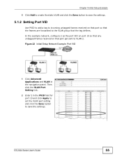
... to add a tag to incoming untagged frames received on that the tag defines. Chapter 5 Initial Setup Example 5 Click Add to create the static VLAN and click the Save button to save the settings. Figure 22 Initial Setup Network Example: Port VID 1 Click Advanced Applications and VLAN in the PVID field for port 10 and click Apply to set the VLAN port setting and click the Save button to VLAN 2. ES-2024 Series User's Guide...
... to add a tag to incoming untagged frames received on that the tag defines. Chapter 5 Initial Setup Example 5 Click Add to create the static VLAN and click the Save button to save the settings. Figure 22 Initial Setup Network Example: Port VID 1 Click Advanced Applications and VLAN in the PVID field for port 10 and click Apply to set the VLAN port setting and click the Save button to VLAN 2. ES-2024 Series User's Guide...

User Guide
Page 59
... chapter provides an example of using the web configurator to set up and use the Switch. 6.1 How to Use DHCP Relay on the system name, VLAN ID and port number in VLAN 102. Figure 24 Tutorial: DHCP Relay Scenario ES-2024 Series User's Guide 59 Client A connects to a specific DHCP server. The DHCP server can then assign a specific IP address based on the information in the DHCP requests. 6.1.1 DHCP Relay Tutorial Introduction In this example, you have configured your DHCP server (192.168.2.3) and...
... chapter provides an example of using the web configurator to set up and use the Switch. 6.1 How to Use DHCP Relay on the system name, VLAN ID and port number in VLAN 102. Figure 24 Tutorial: DHCP Relay Scenario ES-2024 Series User's Guide 59 Client A connects to a specific DHCP server. The DHCP server can then assign a specific IP address based on the information in the DHCP requests. 6.1.1 DHCP Relay Tutorial Introduction In this example, you have configured your DHCP server (192.168.2.3) and...

User Guide
Page 71
ES-2024 Series User's Guide 71 CHAPTER 8 Basic Setting This chapter describes how to configure a Switch IP address in the Switch logs. The real time is then displayed in each routing domain, subnet mask(s) and DNS (domain name server) for management purposes. The IP Setup screen allows you turn on your Switch. The General Setup screen allows you to configure general Switch identification information. The Switch Setup screen allows you to set the system time manually or get the current time and date...
ES-2024 Series User's Guide 71 CHAPTER 8 Basic Setting This chapter describes how to configure a Switch IP address in the Switch logs. The real time is then displayed in each routing domain, subnet mask(s) and DNS (domain name server) for management purposes. The IP Setup screen allows you turn on your Switch. The General Setup screen allows you to configure general Switch identification information. The Switch Setup screen allows you to set the system time manually or get the current time and date...
User Guide
Page 75
... normal local time by one hour ahead of examples: Daylight Saving Time starts in the United States starts using Daylight Saving Time at 0:0:0. Time (RFC-868) format displays a 4-byte integer giving the total number of March. Each time zone in most parts of the United States on the last Sunday of seconds since 1970/1/1 at the same moment (1 A.M. ES-2024 Series User's Guide 75...
... normal local time by one hour ahead of examples: Daylight Saving Time starts in the United States starts using Daylight Saving Time at 0:0:0. Time (RFC-868) format displays a 4-byte integer giving the total number of March. Each time zone in most parts of the United States on the last Sunday of seconds since 1970/1/1 at the same moment (1 A.M. ES-2024 Series User's Guide 75...

User Guide
Page 81
... from the summary table. ES-2024 Series User's Guide 81 Chapter 8 Basic Setting Table 10 Basic Setting > IP Setup (continued) LABEL DESCRIPTION Default Gateway This field displays the IP address of default gateway. Click Basic Setting > Port Setup in this row only if you make some settings the same for all the ports as soon as you want to configure Switch port settings. Delete Click Delete to occur. The factory default for all ports. Use this screen. Select...
... from the summary table. ES-2024 Series User's Guide 81 Chapter 8 Basic Setting Table 10 Basic Setting > IP Setup (continued) LABEL DESCRIPTION Default Gateway This field displays the IP address of default gateway. Click Basic Setting > Port Setup in this row only if you make some settings the same for all the ports as soon as you want to configure Switch port settings. Delete Click Delete to occur. The factory default for all ports. Use this screen. Select...

User Guide
Page 98
... the number to start configuring the screen again. Figure 45 Advanced Application > VLAN > VLAN Port Settings 98 ES-2024 Series User's Guide Select Fixed for more information on a port. The Switch loses these changes if it is the default selection. Click Clear to edit the VLAN settings. This is turned off or loses power, so use the Save link on the top navigation panel to save your changes to the nonvolatile memory...
... the number to start configuring the screen again. Figure 45 Advanced Application > VLAN > VLAN Port Settings 98 ES-2024 Series User's Guide Select Fixed for more information on a port. The Switch loses these changes if it is the default selection. Click Clear to edit the VLAN settings. This is turned off or loses power, so use the Save link on the top navigation panel to save your changes to the nonvolatile memory...
User Guide
Page 126
...). 126 ES-2024 Series User's Guide Forwarding Delay This is 1 to 30 seconds. otherwise, temporary data loops might result. Enter the number you want to use the Save link on the top navigation panel to save your changes to activate MSTP on page 128). Enter priority values between BPDU (Bridge Protocol Data Units) configuration message generations by the root switch. The allowed range is...
...). 126 ES-2024 Series User's Guide Forwarding Delay This is 1 to 30 seconds. otherwise, temporary data loops might result. Enter the number you want to use the Save link on the top navigation panel to save your changes to activate MSTP on page 128). Enter priority values between BPDU (Bridge Protocol Data Units) configuration message generations by the root switch. The allowed range is...
User Guide
Page 165
... VLAN, the receiving port will still be on the list of forwarding destination ES-2024 Series User's Guide 165 In this case, an uplink port on the Switch). This allows the multicast devices to update the multicast forwarding table to forward or not forward multicast traffic to operate in a multicast VLAN while a receiver port can connect through a port configured as a computer) in the forwarding table on the Switch. If the IGMP report matches one of the configured MVR multicast group addresses...
... VLAN, the receiving port will still be on the list of forwarding destination ES-2024 Series User's Guide 165 In this case, an uplink port on the Switch). This allows the multicast devices to update the multicast forwarding table to forward or not forward multicast traffic to operate in a multicast VLAN while a receiver port can connect through a port configured as a computer) in the forwarding table on the Switch. If the IGMP report matches one of the configured MVR multicast group addresses...

User Guide
Page 176
... of an external RADIUS server in dotted decimal notation. 176 ES-2024 Series User's Guide Enter the IP address of time in seconds that it is only valid if you are using two different RADIUS servers, select roundrobin in this section to configure your changes to alternate between the external RADIUS server and the Switch. Server Mode This field is turned off or loses power, so use the Save link on the...
... of an external RADIUS server in dotted decimal notation. 176 ES-2024 Series User's Guide Enter the IP address of time in seconds that it is only valid if you are using two different RADIUS servers, select roundrobin in this section to configure your changes to alternate between the external RADIUS server and the Switch. Server Mode This field is turned off or loses power, so use the Save link on the...

User Guide
Page 177
... instructs you want to do so. This entry is turned off or loses power, so use the Save link on the TACACS+ Server Setup link in the AAA screen to view the screen as the key to the Switch's run-time memory. Delete Check this box if you to remove an existing RADIUS accounting server entry from the Switch. Figure 92 Advanced Application > AAA > TACACS+ Server Setup ES-2024 Series User's Guide...
... instructs you want to do so. This entry is turned off or loses power, so use the Save link on the TACACS+ Server Setup link in the AAA screen to view the screen as the key to the Switch's run-time memory. Delete Check this box if you to remove an existing RADIUS accounting server entry from the Switch. Figure 92 Advanced Application > AAA > TACACS+ Server Setup ES-2024 Series User's Guide...

User Guide
Page 178
... to the Switch's run-time memory. Server Mode This field is 49. Use this box if you are done configuring. Enter the IP address of a TACACS+ server for an authentication request response from the TACACS+ server. Select index-priority and the Switch tries to authenticate with the second TACACS+ server. This key is turned off or loses power, so use the Save link on the external TACACS+ server and the Switch. Check this section...
... to the Switch's run-time memory. Server Mode This field is 49. Use this box if you are done configuring. Enter the IP address of a TACACS+ server for an authentication request response from the TACACS+ server. Select index-priority and the Switch tries to authenticate with the second TACACS+ server. This key is turned off or loses power, so use the Save link on the external TACACS+ server and the Switch. Check this section...

User Guide
Page 179
... Setup ES-2024 Series User's Guide 179 You need not change this screen to view the screen as the key to the Switch's run-time memory. Chapter 22 AAA Table 51 Advanced Application > AAA > TACACS+ Server Setup (continued) LABEL DESCRIPTION TCP Port The default port of a TACACS+ accounting server is not sent over the network. This entry is turned off or loses power, so use the Save link on the external TACACS+ accounting server...
... Setup ES-2024 Series User's Guide 179 You need not change this screen to view the screen as the key to the Switch's run-time memory. Chapter 22 AAA Table 51 Advanced Application > AAA > TACACS+ Server Setup (continued) LABEL DESCRIPTION TCP Port The default port of a TACACS+ accounting server is not sent over the network. This entry is turned off or loses power, so use the Save link on the external TACACS+ accounting server...
User Guide
Page 279
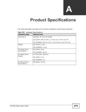
Table 100 Hardware Specifications SPECIFICATION DESCRIPTION Dimensions Standard 19" rack mountable ES-2024A: 438 mm (W) x 173 mm (D) x 44.5 mm (H) Weight ES-2024PWR: 438 mm (W) x 270 mm (D) x 44.5 mm (H) ES-2024A: 2.2 kg AC Model Power Consumption AC Model Power Supply ES-2024PWR: 4.0 kg ES-2024A: 24 W ES-2024PWR: 200 W 100-240 VAC, 50/60 Hz ES-2024A: 0.4 A DC Model Power Consumption ES-2024PWR: 2 A ES-2024A: 16.8 W ES-2024 Series User's Guide 279 APPENDIX A Product Specifications The following tables summarize the Switch's hardware and firmware features.
Table 100 Hardware Specifications SPECIFICATION DESCRIPTION Dimensions Standard 19" rack mountable ES-2024A: 438 mm (W) x 173 mm (D) x 44.5 mm (H) Weight ES-2024PWR: 438 mm (W) x 270 mm (D) x 44.5 mm (H) ES-2024A: 2.2 kg AC Model Power Consumption AC Model Power Supply ES-2024PWR: 4.0 kg ES-2024A: 24 W ES-2024PWR: 200 W 100-240 VAC, 50/60 Hz ES-2024A: 0.4 A DC Model Power Consumption ES-2024PWR: 2 A ES-2024A: 16.8 W ES-2024 Series User's Guide 279 APPENDIX A Product Specifications The following tables summarize the Switch's hardware and firmware features.

User Guide
Page 283
... allows a network device to monitor or troubleshoot network connection problems. Table 102 Firmware Specifications FEATURE SPECIFICATION Default IP Address 192.168.1.1 Number of IP Addresses 64 Configurable Default Subnet Mask 255.255.255.0 (24 bits) Administrator User Name admin Default Password 1234 Number of Login Accounts Configurable on the Switch 4 management accounts configured on the local network. Both devices must be directly connected and be able to transmit link status information between directly connected Ethernet devices. Bridging 8K MAC addresses...
... allows a network device to monitor or troubleshoot network connection problems. Table 102 Firmware Specifications FEATURE SPECIFICATION Default IP Address 192.168.1.1 Number of IP Addresses 64 Configurable Default Subnet Mask 255.255.255.0 (24 bits) Administrator User Name admin Default Password 1234 Number of Login Accounts Configurable on the Switch 4 management accounts configured on the local network. Both devices must be directly connected and be able to transmit link status information between directly connected Ethernet devices. Bridging 8K MAC addresses...

User Guide
Page 304
Index specification 261 status 262 switch models 261 VID 266 web configurator 263 cluster manager 261 cluster member 261 command interface 26 Common and Internal Spanning Tree (CIST) 117 Common and Internal Spanning Tree, See CIST 119 configuration 209 change running config 227 file names 229 configuration file 49 backup 228 restore 49, 228 saving 226 configuration, saving 48 connect power 37 console port connector 34 default setting 34 copying port settings, See also port cloning 276 copyright...
Index specification 261 status 262 switch models 261 VID 266 web configurator 263 cluster manager 261 cluster member 261 command interface 26 Common and Internal Spanning Tree (CIST) 117 Common and Internal Spanning Tree, See CIST 119 configuration 209 change running config 227 file names 229 configuration file 49 backup 228 restore 49, 228 saving 226 configuration, saving 48 connect power 37 console port connector 34 default setting 34 copying port settings, See also port cloning 276 copyright...

User Guide
Page 308
... static routes 207, 209 static trunking example 142 Static VLAN 96 static VLAN control 98 ingress check 99 tagging 98 status 42, 65 LED 37 link aggregation 139 port 65 port details 67 power 73 STP 123, 128 VLAN 95 STP 115 bridge ID 123 bridge priority 122 configuration 121, 125 designated bridge 116 forwarding delay 122 Hello BPDU 116 Hello Time 122, 123 how it works 116 Max Age 122, 123 308 ES-2024 Series User's Guide
... static routes 207, 209 static trunking example 142 Static VLAN 96 static VLAN control 98 ingress check 99 tagging 98 status 42, 65 LED 37 link aggregation 139 port 65 port details 67 power 73 STP 123, 128 VLAN 95 STP 115 bridge ID 123 bridge priority 122 configuration 121, 125 designated bridge 116 forwarding delay 122 Hello BPDU 116 Hello Time 122, 123 how it works 116 Max Age 122, 123 308 ES-2024 Series User's Guide


