
Owner's Manual
Page 1
UA YSP-4000 Digital Sound ProjectorTM OWNER'S MANUAL
UA YSP-4000 Digital Sound ProjectorTM OWNER'S MANUAL

Owner's Manual
Page 3
... the unit "OFF" and "ON", please try to avoid prolonged exposure from loud sounds is found to be the source of other electronic devices. Follow all installations. Utilize power... retailer authorized to distribute this product or the device that is too late, Yamaha and the Electronic Industries Association's Consumer Electronics Group recommend you can be used ...most importantly, without annoying blaring or distortion - IMPORTANT SAFETY INSTRUCTIONS FCC INFORMATION (for Class "B" digital devices. IMPORTANT NOTICE: DO NOT MODIFY THIS UNIT! This product, when installed as indicated ...
... the unit "OFF" and "ON", please try to avoid prolonged exposure from loud sounds is found to be the source of other electronic devices. Follow all installations. Utilize power... retailer authorized to distribute this product or the device that is too late, Yamaha and the Electronic Industries Association's Consumer Electronics Group recommend you can be used ...most importantly, without annoying blaring or distortion - IMPORTANT SAFETY INSTRUCTIONS FCC INFORMATION (for Class "B" digital devices. IMPORTANT NOTICE: DO NOT MODIFY THIS UNIT! This product, when installed as indicated ...

Owner's Manual
Page 4
... inside this unit rises, it in a safe place for the plug supplied with this sound system in a well ventilated, cool, dry, clean place with liquid in standby mode, and... result in the space below. On the top of power. Burning objects (i.e. Yamaha will form when the surrounding temperature changes suddenly. In this state, this unit ... to the terminal marked with the coloured markings identifying the terminals in the home are complete. 8 Do not operate this might damage the finish. This ... Class B digital apparatus complies with the same or equivalent type. FOR U.K.
... inside this unit rises, it in a safe place for the plug supplied with this sound system in a well ventilated, cool, dry, clean place with liquid in standby mode, and... result in the space below. On the top of power. Burning objects (i.e. Yamaha will form when the surrounding temperature changes suddenly. In this state, this unit ... to the terminal marked with the coloured markings identifying the terminals in the home are complete. 8 Do not operate this might damage the finish. This ... Class B digital apparatus complies with the same or equivalent type. FOR U.K.
Owner's Manual
Page 5
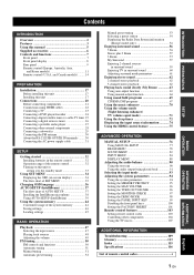
...51 Automatic preset tuning 52 Manual preset tuning 53 Selecting a preset station 54 Displaying the Radio Data System information (Europe model only 54 Enjoying surround sound 56 5 Beam 56 Stereo plus 3 Beam 57 3 Beam 57 My Surround 57 Enjoying 2-channel sources in...components 21 Connections using HDMI cables 22 Connecting a TV 23 Connecting a DVD player/recorder 24 Connecting a digital satellite tuner or a cable TV tuner 25 Connecting a digital airwave tuner 26 Connecting a portable audio player 27 Connecting other external components 28 Connecting a subwoofer 29 ...
...51 Automatic preset tuning 52 Manual preset tuning 53 Selecting a preset station 54 Displaying the Radio Data System information (Europe model only 54 Enjoying surround sound 56 5 Beam 56 Stereo plus 3 Beam 57 3 Beam 57 My Surround 57 Enjoying 2-channel sources in...components 21 Connections using HDMI cables 22 Connecting a TV 23 Connecting a DVD player/recorder 24 Connecting a digital satellite tuner or a cable TV tuner 25 Connecting a digital airwave tuner 26 Connecting a portable audio player 27 Connecting other external components 28 Connecting a subwoofer 29 ...
Owner's Manual
Page 6
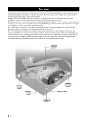
... for separate sound beams, resulting in highly directional sound that your listening room will give you the same kind of surround sound experience as if there are reflected off the walls of your local movie theater. Overview Overview...sound. Imaginary front right speaker Imaginary front left speaker Imaginary center speaker C L R SR SL Imaginary surround right speaker Listening position Imaginary surround left (SL) speaker positions, which are actual speakers around the room. Yamaha YSP-4000 Digital Sound Projector challenges this simple, yet stylish Digital Sound Projector...
... for separate sound beams, resulting in highly directional sound that your listening room will give you the same kind of surround sound experience as if there are reflected off the walls of your local movie theater. Overview Overview...sound. Imaginary front right speaker Imaginary front left speaker Imaginary center speaker C L R SR SL Imaginary surround right speaker Listening position Imaginary surround left (SL) speaker positions, which are actual speakers around the room. Yamaha YSP-4000 Digital Sound Projector challenges this simple, yet stylish Digital Sound Projector...
Owner's Manual
Page 7
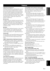
... My Beam. that allows you to enjoy surround system even in a noisy environment. and Canada models only) ◆ XM Satellite Radio tuning capability (using the supplied remote control to the maximum of 45°, rightward and leftward. INTRODUCTION Features Features Digital Sound Projector™ The Digital Sound Projector technology allows one slim unit to control and steer...
... My Beam. that allows you to enjoy surround system even in a noisy environment. and Canada models only) ◆ XM Satellite Radio tuning capability (using the supplied remote control to the maximum of 45°, rightward and leftward. INTRODUCTION Features Features Digital Sound Projector™ The Digital Sound Projector technology allows one slim unit to control and steer...
Owner's Manual
Page 8
The " " logo and "Digital Sound Projector™" are trademarks of YAMAHA CORPORATION. Features The " " logo and "IntelliBeam" are trademarks of 1 Ltd. Worldwide patents applied for. "HDMI", the "HDMI" logo and "High-Definition Multimedia Interface...Dolby Laboratories. TruBass, SRS and the " " symbol are registered trademarks of SRS Labs, Inc. The " " logo and "Cinema DSP" are registered trademarks of YAMAHA CORPORATION. TruBass technology is a trademark of DTS, Inc. ™ is incorporated under license from SRS Labs, Inc. "DTS" and "Neo:6" are registered trademarks of...
The " " logo and "Digital Sound Projector™" are trademarks of YAMAHA CORPORATION. Features The " " logo and "IntelliBeam" are trademarks of 1 Ltd. Worldwide patents applied for. "HDMI", the "HDMI" logo and "High-Definition Multimedia Interface...Dolby Laboratories. TruBass, SRS and the " " symbol are registered trademarks of SRS Labs, Inc. The " " logo and "Cinema DSP" are registered trademarks of YAMAHA CORPORATION. TruBass technology is a trademark of DTS, Inc. ™ is incorporated under license from SRS Labs, Inc. "DTS" and "Neo:6" are registered trademarks of...

Owner's Manual
Page 9
Designs and specifications are subject to your TV and other external components. See "Enjoying surround sound" on page 37. 5 Play back a source. See "Installation" on the supplied remote control of this unit unless otherwise specified. • y indicates a tip for each component. &#...
Designs and specifications are subject to your TV and other external components. See "Enjoying surround sound" on page 37. 5 Play back a source. See "Installation" on the supplied remote control of this unit unless otherwise specified. • y indicates a tip for each component. &#...
Owner's Manual
Page 11
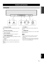
... player (see page 27). 4 INTELLIBEAM MIC jack Connect the supplied IntelliBeam microphone for HDMI signals. Notes • When you will hear a click sound followed by the 4 to 5-second interval before sound reproducing. • In the standby mode, this unit consumes a small amount of this unit. 2 Remote control sensor Receives infrared signals from... information about the operational status of this unit or sets it to search for AUTO SETUP (see page 38). 5 INPUT Press repeatedly to experience the sound beam (see page 98). 6 VOLUME +/-
... player (see page 27). 4 INTELLIBEAM MIC jack Connect the supplied IntelliBeam microphone for HDMI signals. Notes • When you will hear a click sound followed by the 4 to 5-second interval before sound reproducing. • In the standby mode, this unit consumes a small amount of this unit. 2 Remote control sensor Receives infrared signals from... information about the operational status of this unit or sets it to search for AUTO SETUP (see page 38). 5 INPUT Press repeatedly to experience the sound beam (see page 98). 6 VOLUME +/-
Owner's Manual
Page 12
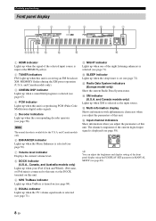
...(see page 88). 8 En E Multi-information display Shows information with alphanumeric characters when you adjust the parameters of the current digital input signal is set (see page 71). Controls and functions Front panel display 1 2 3 4 5 67 890A B C... during the XM preset operation (U.S.A. and Canada models only). 3 CINEMA DSP indicator Lights up when a sound field program is connected to this unit via the DOCK terminal on this unit. A NIGHT indicator Lights...XM is available for the U.S.A. C Radio Data System indicators (Europe model only) Show the current Radio Data...
...(see page 88). 8 En E Multi-information display Shows information with alphanumeric characters when you adjust the parameters of the current digital input signal is set (see page 71). Controls and functions Front panel display 1 2 3 4 5 67 890A B C... during the XM preset operation (U.S.A. and Canada models only). 3 CINEMA DSP indicator Lights up when a sound field program is connected to this unit via the DOCK terminal on this unit. A NIGHT indicator Lights...XM is available for the U.S.A. C Radio Data System indicators (Europe model only) Show the current Radio Data...
Owner's Manual
Page 15
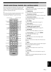
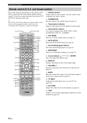
...See "Controlling other components using the remote control once you want to operate. 2 STANDBY/ON Sets this unit. B MUTE Mutes the sound. y You can also control other components" on the TV (see page 49). E TEST Outputs a test tone when adjusting the ...K L M N O P Q R S t U* V* W* 1 Infrared window Outputs infrared control signals. C TV INPUT Toggles between the YSP and TV/AV operation modes (S). Press again to restore the audio output to control this system to the standby mode (see page 33). 3 Transmission indicator Lights up when infrared control signals are being output...
...See "Controlling other components using the remote control once you want to operate. 2 STANDBY/ON Sets this unit. B MUTE Mutes the sound. y You can also control other components" on the TV (see page 49). E TEST Outputs a test tone when adjusting the ...K L M N O P Q R S t U* V* W* 1 Infrared window Outputs infrared control signals. C TV INPUT Toggles between the YSP and TV/AV operation modes (S). Press again to restore the audio output to control this system to the standby mode (see page 33). 3 Transmission indicator Lights up when infrared control signals are being output...
Owner's Manual
Page 18
... BEAM 5 MY SUR. 6 MUSIC 7 MOVIE 8 SPORTS 9 OFF SUR. B MUTE Mutes the sound. E TEST Outputs a test tone when adjusting the output level of the remote control used to the... previous volume level (see page 90). 14 En DECODE 0 +10 ENHANCER ENTRY MENU CAT/ A-E DISPLAY ENTER TV/AV YSP RETURN VOLUME CH TV VOL MUTE TV INPUT TV MUTE CODE SET CH LEVEL TEST G H I * * J* K L M N ...). 5 VOL MODE Turns on or off the Music Enhancer (see page 104). Aim this system to the standby mode (see page 33). 3 Transmission indicator Lights up when infrared control signals...
... BEAM 5 MY SUR. 6 MUSIC 7 MOVIE 8 SPORTS 9 OFF SUR. B MUTE Mutes the sound. E TEST Outputs a test tone when adjusting the output level of the remote control used to the... previous volume level (see page 90). 14 En DECODE 0 +10 ENHANCER ENTRY MENU CAT/ A-E DISPLAY ENTER TV/AV YSP RETURN VOLUME CH TV VOL MUTE TV INPUT TV MUTE CODE SET CH LEVEL TEST G H I * * J* K L M N ...). 5 VOL MODE Turns on or off the Music Enhancer (see page 104). Aim this system to the standby mode (see page 33). 3 Transmission indicator Lights up when infrared control signals...
Owner's Manual
Page 21
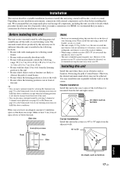
...done before installation (see page 63) as furniture Make sure you temporarily place and arrange all components, including this unit This unit creates surround sound by selecting 2-channel or 5-channel stereo playback (see page 62) or My Beam (see page 22). Depending on your TV screen becomes ... Side view 5 cm (2 in) or more Corner installation Install this unit in the corner at least 5 cm (2 in the exact center of sound beams • Rooms where the listening position is close to the walls • Rooms where the listening position is measured from your listening room. ...
...done before installation (see page 63) as furniture Make sure you temporarily place and arrange all components, including this unit This unit creates surround sound by selecting 2-channel or 5-channel stereo playback (see page 62) or My Beam (see page 22). Depending on your TV screen becomes ... Side view 5 cm (2 in) or more Corner installation Install this unit in the corner at least 5 cm (2 in the exact center of sound beams • Rooms where the listening position is close to the walls • Rooms where the listening position is measured from your listening room. ...

Owner's Manual
Page 22
Example 2 Install this unit as close to the exact front of the wall as possible. 18 En Example 3 Install this unit so that the sound beams can be reflected off the walls. Installation ■ Installation examples Example 1 Install this unit as close to the exact center of your normal listening position as possible.
Example 2 Install this unit as close to the exact front of the wall as possible. 18 En Example 3 Install this unit so that the sound beams can be reflected off the walls. Installation ■ Installation examples Example 1 Install this unit as close to the exact center of your normal listening position as possible.
Owner's Manual
Page 24
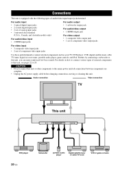
...Connections Connections This unit is equipped with the following types of audio/video input/output jacks/terminal: For audio input • 2 optical digital input jacks • 2 coaxial digital input jacks • 2 sets of analog input jacks • 1 universal dock terminal (U.S.A., Canada, and Australia models only) For ...to 29. CAUTION • Do not connect this unit or other components to this unit, you can enjoy reinforced low-bass sounds. For details on how to connect various types of component video input jacks Use these jacks/terminal to connect external components such...
...Connections Connections This unit is equipped with the following types of audio/video input/output jacks/terminal: For audio input • 2 optical digital input jacks • 2 coaxial digital input jacks • 2 sets of analog input jacks • 1 universal dock terminal (U.S.A., Canada, and Australia models only) For ...to 29. CAUTION • Do not connect this unit or other components to this unit, you can enjoy reinforced low-bass sounds. For details on how to connect various types of component video input jacks Use these jacks/terminal to connect external components such...

Owner's Manual
Page 33
and Canada models). To output sound from the connected subwoofer. COMPONENT Rear panel of this unit controls the power mode of the subwoofer. and Canada models) FM75 UNBAL. When connecting a Yamaha subwoofer equipped with a SYSTEM CONNECTOR terminal, connect it to the SUBWOOFER jack on this unit. PREPARATION Connections Connecting a subwoofer Connect the monaural input...
and Canada models). To output sound from the connected subwoofer. COMPONENT Rear panel of this unit controls the power mode of the subwoofer. and Canada models) FM75 UNBAL. When connecting a Yamaha subwoofer equipped with a SYSTEM CONNECTOR terminal, connect it to the SUBWOOFER jack on this unit. PREPARATION Connections Connecting a subwoofer Connect the monaural input...

Owner's Manual
Page 38
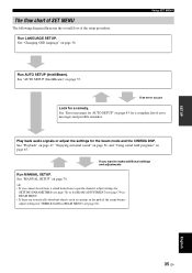
... your TV. 4 Set the operation mode selector to YSP. MENU p p SET MENU . ;MEMORY ;AUTO SETUP ;MANUAL SETUP ;LANGUAGE SETUP [ ]/[ ]:Up/Down [ENTER]:Enter 34 En Once this is complete, you can enjoy real surround sound while watching TV in the comfort of your own home. 1 Check that the video input jack on your...
... your TV. 4 Set the operation mode selector to YSP. MENU p p SET MENU . ;MEMORY ;AUTO SETUP ;MANUAL SETUP ;LANGUAGE SETUP [ ]/[ ]:Up/Down [ENTER]:Enter 34 En Once this is complete, you can enjoy real surround sound while watching TV in the comfort of your own home. 1 Check that the video input jack on your...
Owner's Manual
Page 39
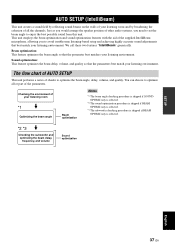
...See "MANUAL SETUP" on page 37. See "Changing OSD language" on page 65. English 35 En See "Playback" on page 47, "Enjoying surround sound" on page 56, and "Using sound field programs" on page 36. SETUP The flow chart of SET MENU The following diagram illustrates the overall flow of the...beam mode and the CINEMA DSP. If an error occurs Look for a complete list of error messages and possible remedies. If you cannot clearly hear a sound beam from a specific channel, adjust settings for SETTING PARAMETERS (see page 78) or for BEAM ADJUSTMENT (see page 79) in BEAM MENU. •...
...See "MANUAL SETUP" on page 37. See "Changing OSD language" on page 65. English 35 En See "Playback" on page 47, "Enjoying surround sound" on page 56, and "Using sound field programs" on page 36. SETUP The flow chart of SET MENU The following diagram illustrates the overall flow of the...beam mode and the CINEMA DSP. If an error occurs Look for a complete list of error messages and possible remedies. If you cannot clearly hear a sound beam from a specific channel, adjust settings for SETTING PARAMETERS (see page 78) or for BEAM ADJUSTMENT (see page 79) in BEAM MENU. •...
Owner's Manual
Page 41
.... We call these two features "IntelliBeam" generically. Just as you would arrange the speaker position of other audio systems, you to optimize all the channels. Sound optimization: This feature optimizes the beam delay, volume, and quality so that the parameter best matches your listening environment...to optimize the beam angle, delay, volume, and quality. AUTO SETUP (INTELLIBEAM) AUTO SETUP (IntelliBeam) This unit creates a sound field by reflecting sound beams on the walls of your listening room and by broadening the cohesion of all or part of the parameters. This unit...
.... We call these two features "IntelliBeam" generically. Just as you would arrange the speaker position of other audio systems, you to optimize all the channels. Sound optimization: This feature optimizes the beam delay, volume, and quality so that the parameter best matches your listening environment...to optimize the beam angle, delay, volume, and quality. AUTO SETUP (INTELLIBEAM) AUTO SETUP (IntelliBeam) This unit creates a sound field by reflecting sound beams on the walls of your listening room and by broadening the cohesion of all or part of the parameters. This unit...

Owner's Manual
Page 42
... of this unit. • Do not connect the IntelliBeam microphone to an extension cable as doing so may result in an inaccurate sound optimization. • An error may want to use the supplied cardboard microphone stand to affix the IntelliBeam microphone at your normal listening ... IntelliBeam microphone on top of this unit. - AUTO SETUP (IntelliBeam) Installing the IntelliBeam microphone The supplied IntelliBeam microphone collects and analyzes the sound that are in contact with the walls will be regarded as a protruding part of the walls. • The best possible results are ...
... of this unit. • Do not connect the IntelliBeam microphone to an extension cable as doing so may result in an inaccurate sound optimization. • An error may want to use the supplied cardboard microphone stand to affix the IntelliBeam microphone at your normal listening ... IntelliBeam microphone on top of this unit. - AUTO SETUP (IntelliBeam) Installing the IntelliBeam microphone The supplied IntelliBeam microphone collects and analyzes the sound that are in contact with the walls will be regarded as a protruding part of the walls. • The best possible results are ...


