
SPX990 Owners Manual Image
Page 2
... not guarantee that is coloured BLUE must be used according to the instructions found to products distributed by the FCC, to co-axial type cable. The wires in this mains lead are on different branch (circuit breaker or fuse) circuits or install AC line filter/s. If you can be determined by turning the unit "OFF" and "ON", please try...
... not guarantee that is coloured BLUE must be used according to the instructions found to products distributed by the FCC, to co-axial type cable. The wires in this mains lead are on different branch (circuit breaker or fuse) circuits or install AC line filter/s. If you can be determined by turning the unit "OFF" and "ON", please try...
SPX990 Owners Manual Image
Page 3
... EQ, compressor, Aural Exciter®, or distortion can be used in the internal RAM memory can be switched to OUT, edited programs stored in the post-effect program. As an extra touch of convenience, the SPX990's analog input and output terminals can be dumped to 20kHz for exceptionally clean, "transparent" effect sounds and direct digital interfacing capabilities making new effects like the main effect programs include multi-tap delay for accurate...
... EQ, compressor, Aural Exciter®, or distortion can be used in the internal RAM memory can be switched to OUT, edited programs stored in the post-effect program. As an extra touch of convenience, the SPX990's analog input and output terminals can be dumped to 20kHz for exceptionally clean, "transparent" effect sounds and direct digital interfacing capabilities making new effects like the main effect programs include multi-tap delay for accurate...
SPX990 Owners Manual Image
Page 4
... SPECIFICATIONS OPTION BLOCK DIAGRAM DIMENSIONS MIDI DATA FORMAT MIDI Implementation Chart USER PROGRAMMING TABLE MIDI PROGRAM CHANGE LIST Add-1 Add-1 Add-4 Add-4 Add-5 Add-10 Add-11 Add-13 * Aural Exciter® is a registered trademark and is manufactured under license from Aphex Systems, Ltd. 2 CONTENTS PRECAUTIONS 3 CONTROLS AND CONNECTIONS 4 THE FRONT PANEL 4 THE REAR PANEL 5 THE SPX990 SYSTEM 6 EFFECT CONFIGURATION 6 MEMORY CONFIGURATION 7 MEMORY CARD 7 MEMORY & EDIT MODES 8 SELECTING AN INPUT MODE 9 (Edit Mode: Page 5) GENERAL OPERATION 10 MEMORY RECALL...
... SPECIFICATIONS OPTION BLOCK DIAGRAM DIMENSIONS MIDI DATA FORMAT MIDI Implementation Chart USER PROGRAMMING TABLE MIDI PROGRAM CHANGE LIST Add-1 Add-1 Add-4 Add-4 Add-5 Add-10 Add-11 Add-13 * Aural Exciter® is a registered trademark and is manufactured under license from Aphex Systems, Ltd. 2 CONTENTS PRECAUTIONS 3 CONTROLS AND CONNECTIONS 4 THE FRONT PANEL 4 THE REAR PANEL 5 THE SPX990 SYSTEM 6 EFFECT CONFIGURATION 6 MEMORY CONFIGURATION 7 MEMORY CARD 7 MEMORY & EDIT MODES 8 SELECTING AN INPUT MODE 9 (Edit Mode: Page 5) GENERAL OPERATION 10 MEMORY RECALL...
SPX990 Owners Manual Image
Page 5
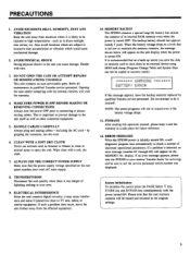
... returned to memory cards). ******* WARNING :•F::1.::}::i BATTERY ERROR If this operation manual, please keep it is too low to maintain the memory contents, the message shown below will be copied to the original settings. 3 If such a problem does occur, move the unit further away from locations where it and the warranty in an external device using MIDI bulk dump (Program Change Table and System Data can cause...
... returned to memory cards). ******* WARNING :•F::1.::}::i BATTERY ERROR If this operation manual, please keep it is too low to maintain the memory contents, the message shown below will be copied to the original settings. 3 If such a problem does occur, move the unit further away from locations where it and the warranty in an external device using MIDI bulk dump (Program Change Table and System Data can cause...
SPX990 Owners Manual Image
Page 6
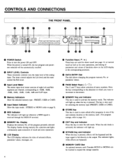
O INPUT LEVEL Controls These concentric controls vary the input level of recall and store operations. selection and lights continuously upon execution of the analog input. O DATA ENTRY Dial The dial allows changing the program memory No. The indicator lights, while effects are used for direct recall (see page 11) or normal recall as well as for selecting the memory type (PRESET, USER or CARD). • STORE Key This key is fed directly to the output. When the power is...
O INPUT LEVEL Controls These concentric controls vary the input level of recall and store operations. selection and lights continuously upon execution of the analog input. O DATA ENTRY Dial The dial allows changing the program memory No. The indicator lights, while effects are used for direct recall (see page 11) or normal recall as well as for selecting the memory type (PRESET, USER or CARD). • STORE Key This key is fed directly to the output. When the power is...

SPX990 Owners Manual Image
Page 7
... nominal output level. Both XLR-3-32 type connectors and TRS phone jacks are analog stereo input terminals. e TRIGGER Footswitch Jack An optional foot switch(Yamaha FC4 or FC5) connected to this terminal can be used to "tap" input parameter settings or to trigger the effect gate in the program selected. • BYPASS or MEMORY INC/DEC Footswitch Jack This terminal can be used to switch settings in the edit mode using one...
... nominal output level. Both XLR-3-32 type connectors and TRS phone jacks are analog stereo input terminals. e TRIGGER Footswitch Jack An optional foot switch(Yamaha FC4 or FC5) connected to this terminal can be used to "tap" input parameter settings or to trigger the effect gate in the program selected. • BYPASS or MEMORY INC/DEC Footswitch Jack This terminal can be used to switch settings in the edit mode using one...
SPX990 Owners Manual Image
Page 9
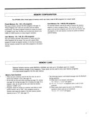
... recall. At the time of purchase, the user memory contains the same effect programs as the preset memory. Also, do not pull out the card when the memory indicator "CARD" is no memory card present, "Ho Ileviord Card" will appear. 7 Also, programs stored on memory card cannot be displayed during operation: When there is lit. • Programs cannot be edited and stored in which your programs. These cards can be used to format...
... recall. At the time of purchase, the user memory contains the same effect programs as the preset memory. Also, do not pull out the card when the memory indicator "CARD" is no memory card present, "Ho Ileviord Card" will appear. 7 Also, programs stored on memory card cannot be displayed during operation: When there is lit. • Programs cannot be edited and stored in which your programs. These cards can be used to format...
SPX990 Owners Manual Image
Page 13
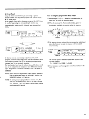
... operation. Its memory number is displayed above the function key and the program will remain in the same way. 11 O PRESET =I USER O CARD B Lights up ). Recalling a program using the panel keys" in an one function key (V / A) for direct recall Ql Perform steps a® in front of "Recalling a program using the panel keys" to assign the program. **,* O PRESET E=1 USER'" O CARDo. / B CONCERT HALL Recall? :7U05 P01 C07 P48 No Yes • A Flashes The program is identified by pressing the corresponding A function key. 2. NOTE: Direct recall can...
... operation. Its memory number is displayed above the function key and the program will remain in the same way. 11 O PRESET =I USER O CARD B Lights up ). Recalling a program using the panel keys" in an one function key (V / A) for direct recall Ql Perform steps a® in front of "Recalling a program using the panel keys" to assign the program. **,* O PRESET E=1 USER'" O CARDo. / B CONCERT HALL Recall? :7U05 P01 C07 P48 No Yes • A Flashes The program is identified by pressing the corresponding A function key. 2. NOTE: Direct recall can...

SPX990 Owners Manual Image
Page 18
... memory No. indicator will appear on a memory card to the user memory or copy (save) all data in the user or card memory for later use. CZMSSI MEMORY O PRESET E3 USER O CARD NOTE: When storing an edited program on page 15). NOTE: The BYPASS ON/OFF setting is stored in which is presently recalled, recall that program. ® Press the STORE key to activate the "'Store" mode. No 'YIDS I AI VIA I 1 Flashes...
... memory No. indicator will appear on a memory card to the user memory or copy (save) all data in the user or card memory for later use. CZMSSI MEMORY O PRESET E3 USER O CARD NOTE: When storing an edited program on page 15). NOTE: The BYPASS ON/OFF setting is stored in which is presently recalled, recall that program. ® Press the STORE key to activate the "'Store" mode. No 'YIDS I AI VIA I 1 Flashes...

SPX990 Owners Manual Image
Page 21
... two-digit number identifies the memory type: P= PRESET, Li= USER, C= CARD. ® Set the last program of the edit mode or the MEMORY key to return to the next or previous program in sequence. The recall range setting is pressed, the unit changes to the memory mode. NOTE: For live performances programs can be used to press the STORE key. Each time the foot switch is memorized automatically without having to connect...
... two-digit number identifies the memory type: P= PRESET, Li= USER, C= CARD. ® Set the last program of the edit mode or the MEMORY key to return to the next or previous program in sequence. The recall range setting is pressed, the unit changes to the memory mode. NOTE: For live performances programs can be used to press the STORE key. Each time the foot switch is memorized automatically without having to connect...

SPX990 Owners Manual Image
Page 26
.... SYNC DELAY MODULATION PROGRAMS • Flanger (Ranger) 65. DETUNE CHORUS • FM. Chorus (FM.Cho) 62. SILKY SWEEP • Symphonic (Symphon) 57. SYMPHONIC PITCH CHANGE PROGRAMS • Mono Pitch Change (MonoPit) 49. "LOW" SNARE 47. BOTTOM WHACKER 53. INTELLICHORDTRI • Stereo Pitch Change (StPitch) 56. GTR SYM ECHO • Flanger & Reverb (Flg&Rev) 9. SILVERHEART • Chorus (L) / Reverb (R) (Cho/Rev) 66. CONCERT HALL 10. ARENA • Filtered Reverb (FiltRev...
.... SYNC DELAY MODULATION PROGRAMS • Flanger (Ranger) 65. DETUNE CHORUS • FM. Chorus (FM.Cho) 62. SILKY SWEEP • Symphonic (Symphon) 57. SYMPHONIC PITCH CHANGE PROGRAMS • Mono Pitch Change (MonoPit) 49. "LOW" SNARE 47. BOTTOM WHACKER 53. INTELLICHORDTRI • Stereo Pitch Change (StPitch) 56. GTR SYM ECHO • Flanger & Reverb (Flg&Rev) 9. SILVERHEART • Chorus (L) / Reverb (R) (Cho/Rev) 66. CONCERT HALL 10. ARENA • Filtered Reverb (FiltRev...

SPX990 Owners Manual Image
Page 30
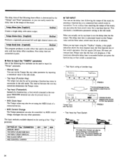
... and Release A short input signal like the one shown in a sound different from closing. By setting a long Hold time the gate can be used for the set hold time, a trigger received while the gate is set to extremely long reverb times (max. 480 seconds). Input Signal Reverb Output TrgLvl Hold Release OTHER TRIGGERS The signal level is set to 0, the gate will open even before the initial delay. A foot switch connected to trigger...
... and Release A short input signal like the one shown in a sound different from closing. By setting a long Hold time the gate can be used for the set hold time, a trigger received while the gate is set to extremely long reverb times (max. 480 seconds). Input Signal Reverb Output TrgLvl Hold Release OTHER TRIGGERS The signal level is set to 0, the gate will open even before the initial delay. A foot switch connected to trigger...
SPX990 Owners Manual Image
Page 36
... mode. • Tap Input (Function Key) The tempo can easily match the delay time to input the "TEMPO" parameter One of the music by pressing a connected foot switch twice. The delay time then is determined by the "Tempo" and "Note" parameters, so you can also be set by pressing a function key twice in succession in the edit mode. The interval between the two key operations determines the delay time. PARAMETER MANUAL INPUT TAP INPUT (FUNCTION KEY) TAP INPUT (FOOT SWITCH) MIDI CLOCK INPUT MIDI CONTROL CHANGE OFF TAP MIDI 0 0 0 x 0 x x 0 x x x 0 0 0 0 • TAP INPUT...
... mode. • Tap Input (Function Key) The tempo can easily match the delay time to input the "TEMPO" parameter One of the music by pressing a connected foot switch twice. The delay time then is determined by the "Tempo" and "Note" parameters, so you can also be set by pressing a function key twice in succession in the edit mode. The interval between the two key operations determines the delay time. PARAMETER MANUAL INPUT TAP INPUT (FUNCTION KEY) TAP INPUT (FOOT SWITCH) MIDI CLOCK INPUT MIDI CONTROL CHANGE OFF TAP MIDI 0 0 0 x 0 x x 0 x x x 0 0 0 0 • TAP INPUT...

SPX990 Owners Manual Image
Page 37
... High Parameters j ® Tempo (Tempo: J = 41 - 250) Indicates the number of quarter notes per minute (beats/ minute). © Note (Note: ,F, F, J., Sets the duration of the sound. The delay value then is displayed as the delay time value is set frequency. A minus value produces a reversed phase. © Diffuse (Diffusion: 0 - 10) Controls the loudness and clearness of sound by tap input using "TapKey" (function switch), foot switch or MIDI. The parameter also...
... High Parameters j ® Tempo (Tempo: J = 41 - 250) Indicates the number of quarter notes per minute (beats/ minute). © Note (Note: ,F, F, J., Sets the duration of the sound. The delay value then is displayed as the delay time value is set frequency. A minus value produces a reversed phase. © Diffuse (Diffusion: 0 - 10) Controls the loudness and clearness of sound by tap input using "TapKey" (function switch), foot switch or MIDI. The parameter also...

SPX990 Owners Manual Image
Page 41
... input sources with the music style according to set to OFF, the chromatic pitch change parameters to control the effect. The program offers 7 preset scales to choose from and allows you to a specified key and scale. When set pitch change amounts for D, etc. After selecting each note (InNote) you do not store the user scale data they will be lost when a different effect program is set within...
... input sources with the music style according to set to OFF, the chromatic pitch change parameters to control the effect. The program offers 7 preset scales to choose from and allows you to a specified key and scale. When set pitch change amounts for D, etc. After selecting each note (InNote) you do not store the user scale data they will be lost when a different effect program is set within...

SPX990 Owners Manual Image
Page 48
... a dual effect program in which the input signal of the left channel is selected, the left and right-channel signals are mixed and then outpu in relation to "Rev/Rev" effect on page 45. 0 RevLPF (REVERB Low Pass Filter Frequency: 1kHz 16kHz, THRU) Permits rolling off the high-frequency content of the Rev signal above ER parameters control the left channel input signal. Output (Output Mode: Stereo, Monox2) When set frequency. CD...
... a dual effect program in which the input signal of the left channel is selected, the left and right-channel signals are mixed and then outpu in relation to "Rev/Rev" effect on page 45. 0 RevLPF (REVERB Low Pass Filter Frequency: 1kHz 16kHz, THRU) Permits rolling off the high-frequency content of the Rev signal above ER parameters control the left channel input signal. Output (Output Mode: Stereo, Monox2) When set frequency. CD...

SPX990 Owners Manual Image
Page 49
... Feed back Gain: -99% - +99%) These parameters for the left channel delay signal fed back to the input of the processor. Echo (L)/ Reverb (R) (Ech/Rev) 21n/tout This is a dual effect program in which the input signal of the left channel is selected, the left and right-channel signals are mixed and then output in stereo. C) L. Output (Output Mode: Stereo, Monox2) When set to the overall reverb time. • Diffuse (REVERB Diffusion: 0 - 10) Sets the complexity...
... Feed back Gain: -99% - +99%) These parameters for the left channel delay signal fed back to the input of the processor. Echo (L)/ Reverb (R) (Ech/Rev) 21n/tout This is a dual effect program in which the input signal of the left channel is selected, the left and right-channel signals are mixed and then output in stereo. C) L. Output (Output Mode: Stereo, Monox2) When set to the overall reverb time. • Diffuse (REVERB Diffusion: 0 - 10) Sets the complexity...

SPX990 Owners Manual Image
Page 50
... set at which the effect varies. CD Typal (1 Pan Type: L R, L R, L R, L-TURN, R-TURN) 02 Speed1 (1 Panning Speed: 0.05Hz - 40.0Hz) 0 F/R Depi (1 Front/Rear Depth: 0% -. 100%) • L/R Dept1 (1 Lch/Rch Depth: 0% - 100%) ® Delayl (1 Initial Delay Time: 0.lmsec 700.0msec) The above are rotated without changing the angle. Two signal inputs create two different Pan effects. Chorus Reverb PAN1 PAN2 Parameters NOTE: Balanl controls the mix level...
... set at which the effect varies. CD Typal (1 Pan Type: L R, L R, L R, L-TURN, R-TURN) 02 Speed1 (1 Panning Speed: 0.05Hz - 40.0Hz) 0 F/R Depi (1 Front/Rear Depth: 0% -. 100%) • L/R Dept1 (1 Lch/Rch Depth: 0% - 100%) ® Delayl (1 Initial Delay Time: 0.lmsec 700.0msec) The above are rotated without changing the angle. Two signal inputs create two different Pan effects. Chorus Reverb PAN1 PAN2 Parameters NOTE: Balanl controls the mix level...
SPX990 Owners Manual Image
Page 51
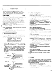
... a sampling frequency of the following pages) using the input signal level as required. When a positive value is selected, the left channel input signal will start point in the internal memory. Each of the sound to the previously recorded sound. • AutRec (Auto Recording) To automatically trigger the recording using the PAGE select keys (6 / 9). NOTE: When the Stereo input mode is set , the input signal will be recorded from an external MIDI keyboard. 49 Freeze (Freeze) 1in/2out...
... a sampling frequency of the following pages) using the input signal level as required. When a positive value is selected, the left channel input signal will start point in the internal memory. Each of the sound to the previously recorded sound. • AutRec (Auto Recording) To automatically trigger the recording using the PAGE select keys (6 / 9). NOTE: When the Stereo input mode is set , the input signal will be recorded from an external MIDI keyboard. 49 Freeze (Freeze) 1in/2out...

SPX990 Owners Manual Image
Page 54
... MIDI terminal of another MIDI device (keyboard, etc.) and set the MIDI parameters accordingly. MIDI OPERATIONS The following operations are possible using MIDI control: ■ Program Change The effect programs of the SPX990 can retransmit these messages to the MIDI OUT terminal of the MIDI OUT/FHRU switch. MIDI stands for "Musical Instrument Digital Interface", the data communication standard for electronic instruments and audio equipment. we MIDI IN This terminal enables the SPX990 to MIDI PROGRAM CHANGE TABLE SETUP...
... MIDI terminal of another MIDI device (keyboard, etc.) and set the MIDI parameters accordingly. MIDI OPERATIONS The following operations are possible using MIDI control: ■ Program Change The effect programs of the SPX990 can retransmit these messages to the MIDI OUT terminal of the MIDI OUT/FHRU switch. MIDI stands for "Musical Instrument Digital Interface", the data communication standard for electronic instruments and audio equipment. we MIDI IN This terminal enables the SPX990 to MIDI PROGRAM CHANGE TABLE SETUP...


