MCXSP10 Manual
Page 1
U AV Receiver STANDBY /ON PURE DIRECT 2CH/MULTI CH INPUT SELECTOR SPEAKERS A B REC OUT/ZONE 2 SOURCE/REMOTE DTV/LD DVD CABLE MD/TAPE SAT CD-R VCR 1 CD VCR 2 DVR VIDEO AUX TUNER PHONO INPUT MODE MULTI CH INPUT STRAIGHT DSP PROGRAM MULTI JOG EFFECT SILENT OPTIMIZER MIC VIDEO AUX BALANCE TONE CONTROL PHONES S VIDEO VIDEO L AUDIO R OPTICAL VOLUME OWNER'S MANUAL
U AV Receiver STANDBY /ON PURE DIRECT 2CH/MULTI CH INPUT SELECTOR SPEAKERS A B REC OUT/ZONE 2 SOURCE/REMOTE DTV/LD DVD CABLE MD/TAPE SAT CD-R VCR 1 CD VCR 2 DVR VIDEO AUX TUNER PHONO INPUT MODE MULTI CH INPUT STRAIGHT DSP PROGRAM MULTI JOG EFFECT SILENT OPTIMIZER MIC VIDEO AUX BALANCE TONE CONTROL PHONES S VIDEO VIDEO L AUDIO R OPTICAL VOLUME OWNER'S MANUAL
MCXSP10 Manual
Page 7
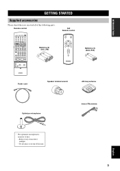
INTRODUCTION GETTING STARTED Supplied accessories Please check that you received all of this unit. English 3 Remote control MACRO TRANSMIT RE-NAME CLEAR LEARN MACRO OFF ON SYSTEM POWER STANDBY V-AUX TUNER PHONO CABLE SAT MD/...
INTRODUCTION GETTING STARTED Supplied accessories Please check that you received all of this unit. English 3 Remote control MACRO TRANSMIT RE-NAME CLEAR LEARN MACRO OFF ON SYSTEM POWER STANDBY V-AUX TUNER PHONO CABLE SAT MD/...
MCXSP10 Manual
Page 9
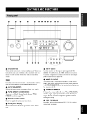
...field programs. 5 English When STRAIGHT is connected to two or more input jacks on this unit (see page 45). 4 Remote control sensor Receives signals from the remote controls. 5 Front panel display Shows information about the operational status of this unit. 6 INPUT MODE Sets the priority ...for the type of input signal (AUTO, i.LINK, DTS, DIGITAL, D.D.RF, ANALOG) received when one component is selected, input signals (2-channel or multi-channel) are output directly from their respective speakers without effect processing. 9 DSP PROGRAM ...
...field programs. 5 English When STRAIGHT is connected to two or more input jacks on this unit (see page 45). 4 Remote control sensor Receives signals from the remote controls. 5 Front panel display Shows information about the operational status of this unit. 6 INPUT MODE Sets the priority ...for the type of input signal (AUTO, i.LINK, DTS, DIGITAL, D.D.RF, ANALOG) received when one component is selected, input signals (2-channel or multi-channel) are output directly from their respective speakers without effect processing. 9 DSP PROGRAM ...
MCXSP10 Manual
Page 11
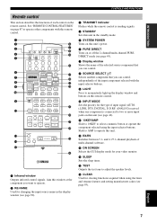
... page 93). B EX/ES Switches between 5.1- C ON SCREEN Selects the GUI display mode for the type of input signal (AUTO, i.LINK, DTS, DIGITAL, D.D.RF, ANALOG) received when one component is sending signals. 4 STANDBY Sets this unit in the display window (see page 90). 3 TRANSMIT indicator Flashes while the remote control is...
... page 93). B EX/ES Switches between 5.1- C ON SCREEN Selects the GUI display mode for the type of input signal (AUTO, i.LINK, DTS, DIGITAL, D.D.RF, ANALOG) received when one component is sending signals. 4 STANDBY Sets this unit in the display window (see page 90). 3 TRANSMIT indicator Flashes while the remote control is...

MCXSP10 Manual
Page 14
... mode. 10 J AUTO indicator Shows that this unit is reproducing PCM (pulse code modulation) digital audio signals. G TUNED indicator Lights up when this unit is receiving a strong signal for an FM stereo broadcast while the "AUTO" indicator is lit. D THX indicators Lights up when a THX program is on. H STEREO indicator Lights...
... mode. 10 J AUTO indicator Shows that this unit is reproducing PCM (pulse code modulation) digital audio signals. G TUNED indicator Lights up when this unit is receiving a strong signal for an FM stereo broadcast while the "AUTO" indicator is lit. D THX indicators Lights up when a THX program is on. H STEREO indicator Lights...
MCXSP10 Manual
Page 21
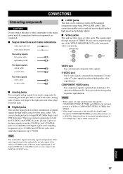
... left jacks. ■ Digital jacks This unit has digital jacks for signals input through the COMPONENT VIDEO jack when Resolution is given to send and receive digital audio at high speed and with i.LINK equipped components using 4-pin, S400 i.LINK cables. COMPONENT VIDEO jacks For component signals, separated into luminance (Y) and...
... left jacks. ■ Digital jacks This unit has digital jacks for signals input through the COMPONENT VIDEO jack when Resolution is given to send and receive digital audio at high speed and with i.LINK equipped components using 4-pin, S400 i.LINK cables. COMPONENT VIDEO jacks For component signals, separated into luminance (Y) and...
MCXSP10 Manual
Page 52
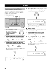
... PRESET/TUNING to select TUNER as described in "Automatic tuning". 2 Press TUNING MODE so that the "AUTO" indicator lights up and the frequency of the received station is weak, you want to select is shown on the front panel display, press PRESET/TUNING to select the reception band. FM/AM or...
... PRESET/TUNING to select TUNER as described in "Automatic tuning". 2 Press TUNING MODE so that the "AUTO" indicator lights up and the frequency of the received station is weak, you want to select is shown on the front panel display, press PRESET/TUNING to select the reception band. FM/AM or...
MCXSP10 Manual
Page 53
... stored station data existing under a preset number is cleared when you want to store is complete, the front panel display shows the frequency of the received stations does not reach E8, automatic preset tuning has automatically stopped after searching all been stored up on the front panel display. After pressing MEMORY...
... stored station data existing under a preset number is cleared when you want to store is complete, the front panel display shows the frequency of the received stations does not reach E8, automatic preset tuning has automatically stopped after searching all been stored up on the front panel display. After pressing MEMORY...
MCXSP10 Manual
Page 54
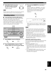
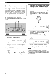
... TONE CONTROL SILENT MIC VIDEO AUX PHONES S VIDEO VIDEO L AUDIO R OPTICAL VOLUME 1 Tune into a station, the front panel display shows the frequency of the station received. 2 Press MEMORY.
... TONE CONTROL SILENT MIC VIDEO AUX PHONES S VIDEO VIDEO L AUDIO R OPTICAL VOLUME 1 Tune into a station, the front panel display shows the frequency of the station received. 2 Press MEMORY.

MCXSP10 Manual
Page 95
...CD To automatically transmit these operations simply by connecting them to start playback. For details, refer to the operation instructions for any YAMAHA remote control-compatible MD recorder, CD player, CD recorder, DVD player, or LD player. When using macros to operate other components... area) (*2) PLAY (CD-R area) (*2) PLAY (CD area) (*2) - The buttons listed as the input source, this unit plays the last station received before the unit was set with this unit. (Power control may not be started for the connected component.) *2 Playback can be synchronized with macro programs...
...CD To automatically transmit these operations simply by connecting them to start playback. For details, refer to the operation instructions for any YAMAHA remote control-compatible MD recorder, CD player, CD recorder, DVD player, or LD player. When using macros to operate other components... area) (*2) PLAY (CD-R area) (*2) PLAY (CD area) (*2) - The buttons listed as the input source, this unit plays the last station received before the unit was set with this unit. (Power control may not be started for the connected component.) *2 Playback can be synchronized with macro programs...
MCXSP10 Manual
Page 104
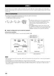
...equipment to this OUT IN OUT IN CONTROL OUT unit in a multi-room installation, we recommend that best meet your requirements. • Some YAMAHA models are not output from the second room. Further, the Zone 2 volume setting does not apply to use an infrared emitter. ZONE 2 VIDEO... DVD player (or other component) This unit DVD INPUT Infrared emitter Main room REMOTE CONTROL OUT Amplifier Video monitor Remote control Infrared signal receiver Second room ZONE 2 REMOTE IN Notes • When not using the main room, turn down the volume of ways you consult your nearest...
...equipment to this OUT IN OUT IN CONTROL OUT unit in a multi-room installation, we recommend that best meet your requirements. • Some YAMAHA models are not output from the second room. Further, the Zone 2 volume setting does not apply to use an infrared emitter. ZONE 2 VIDEO... DVD player (or other component) This unit DVD INPUT Infrared emitter Main room REMOTE CONTROL OUT Amplifier Video monitor Remote control Infrared signal receiver Second room ZONE 2 REMOTE IN Notes • When not using the main room, turn down the volume of ways you consult your nearest...

MCXSP10 Manual
Page 107
... and bi-directional digital interface in length. • This unit supports hot plugging, a function that supports the S400 transmission speed. You can also send and receive uncompressed multi-channel audio signals, such as DVD audio (multi-channel PCM) and Super Audio CD (DSD) multi-channel audio signals using a cable less than...
... and bi-directional digital interface in length. • This unit supports hot plugging, a function that supports the S400 transmission speed. You can also send and receive uncompressed multi-channel audio signals, such as DVD audio (multi-channel PCM) and Super Audio CD (DSD) multi-channel audio signals using a cable less than...
MCXSP10 Manual
Page 108
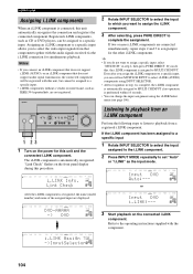
Notes • If you connect an i.LINK component that does not support i.LINK (AUDIO), or an i.LINK component that component together with the audio signals received via the i.LINK connection for simultaneous playback. The i.LINK component is automatically recognized. MULTI CH V-AUX DVR VCR 2 VCR 1 SAT CABLE DTV/LD Input DVD ...
Notes • If you connect an i.LINK component that does not support i.LINK (AUDIO), or an i.LINK component that component together with the audio signals received via the i.LINK connection for simultaneous playback. The i.LINK component is automatically recognized. MULTI CH V-AUX DVR VCR 2 VCR 1 SAT CABLE DTV/LD Input DVD ...
MCXSP10 Manual
Page 110
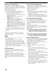
... to display the following information: operation status of the desired component and press ENTER to delete the selected i.LINK component from accidentally being received. Audio (for audio signals) or Non Audio (for the i.LINK component, then press ENTER. ■ Auto Play (Auto Play...LINK component. When you want to V-AUX) or MULTI CH INPUT. i.LINK Select > Auto Play Choices: Z9 → Player, Z9 ← Player, Z9 ↔ Player, Z9 × Player • Select Z9 → Player if you want playback to start automatically on the i.LINK component selected using INPUT SELECTOR. &#...
... to display the following information: operation status of the desired component and press ENTER to delete the selected i.LINK component from accidentally being received. Audio (for audio signals) or Non Audio (for the i.LINK component, then press ENTER. ■ Auto Play (Auto Play...LINK component. When you want to V-AUX) or MULTI CH INPUT. i.LINK Select > Auto Play Choices: Z9 → Player, Z9 ← Player, Z9 ↔ Player, Z9 × Player • Select Z9 → Player if you want playback to start automatically on the i.LINK component selected using INPUT SELECTOR. &#...

MCXSP10 Manual
Page 119
... power cord, plug it as lightning or strong static electricity). Remedy Connect the power cord firmly. Set this unit cannot reproduce are being received from a source component e.g.: a CD-ROM. Play a source whose signals this unit does not function properly. The protection circuitry has been...the power cord, and contact your speakers. The input or output cable connections are not secure. Refer to match your nearest authorized YAMAHA dealer or service center. ■ General Problem This unit fails to turn on this unit and all speaker wire connections on when...
... power cord, plug it as lightning or strong static electricity). Remedy Connect the power cord firmly. Set this unit cannot reproduce are being received from a source component e.g.: a CD-ROM. Play a source whose signals this unit does not function properly. The protection circuitry has been...the power cord, and contact your speakers. The input or output cable connections are not secure. Refer to match your nearest authorized YAMAHA dealer or service center. ■ General Problem This unit fails to turn on this unit and all speaker wire connections on when...

MCXSP10 Manual
Page 128
... imaging behind the listener in most of the listeners being close to provide a wide stable rear soundstage. In addition, all Ultra2 controllers and receivers incorporate video switching capable of handling all 5.1 encoded music sources such as DTS 5.1 music and Dolby Digital 5.1 music. ■ B.G.C. (Boundary...engage the THX Surround EX mode during the mixing of the program. In such case the information delivered to come. THX Ultra2 receivers contain the BGC (Boundary Gain Compensation) feature to reproduce an extra channel which is not Dolby Digital Surround EX encoded. This ...
... imaging behind the listener in most of the listeners being close to provide a wide stable rear soundstage. In addition, all Ultra2 controllers and receivers incorporate video switching capable of handling all 5.1 encoded music sources such as DTS 5.1 music and Dolby Digital 5.1 music. ■ B.G.C. (Boundary...engage the THX Surround EX mode during the mixing of the program. In such case the information delivered to come. THX Ultra2 receivers contain the BGC (Boundary Gain Compensation) feature to reproduce an extra channel which is not Dolby Digital Surround EX encoded. This ...


