

Owner's Manual
Page 2
... inside this unit, which is coloured BROWN must be connected to the terminal which is connected to the earth terminal of power. YAMAHA will not be used. This state is turned off and an appropriate 3 pin plug fitted. I For U.K. Model IMPORTANT THE WIRES IN MAINS LEAD ... condensation inside this unit rises, it may cause fire, damage to this unit. - Burning objects (i.e. Contact qualified YAMAHA service personnel when any reasons. 16 When not planning to use of liquid. 4 Do not expose this unit to sudden temperature changes from the AC power source as long as ...
... inside this unit, which is coloured BROWN must be connected to the terminal which is connected to the earth terminal of power. YAMAHA will not be used. This state is turned off and an appropriate 3 pin plug fitted. I For U.K. Model IMPORTANT THE WIRES IN MAINS LEAD ... condensation inside this unit rises, it may cause fire, damage to this unit. - Burning objects (i.e. Contact qualified YAMAHA service personnel when any reasons. 16 When not planning to use of liquid. 4 Do not expose this unit to sudden temperature changes from the AC power source as long as ...

Owner's Manual
Page 3
...THE EFFECT SPEAKERS 47 SLEEP TIMER 48 Setting the Sleep Timer 48 Canceling the Sleep Timer 48 REMOTE CONTROL FEATURES 49 Selector Dial 49 Commonly Used Buttons in Each Position ...... 51 Setting the Manufacturer Code 54 Programming a New Remote Control Function (Learn Feature 55 Returning to the Factory ...20 SPEAKER MODE SETTINGS 21 Summary of SPEAKER SET Items 1A through 1E 21 ADJUSTING THE SPEAKER OUTPUT LEVELS 22 Before You Begin 22 Using the Test Tone (TEST DOLBY SUR 22 BASIC OPERATION BASIC PLAYBACK 24 Input Modes and Indications 26 Selecting a Sound Field Program 28 Normal...
...THE EFFECT SPEAKERS 47 SLEEP TIMER 48 Setting the Sleep Timer 48 Canceling the Sleep Timer 48 REMOTE CONTROL FEATURES 49 Selector Dial 49 Commonly Used Buttons in Each Position ...... 51 Setting the Manufacturer Code 54 Programming a New Remote Control Function (Learn Feature 55 Returning to the Factory ...20 SPEAKER MODE SETTINGS 21 Summary of SPEAKER SET Items 1A through 1E 21 ADJUSTING THE SPEAKER OUTPUT LEVELS 22 Before You Begin 22 Using the Test Tone (TEST DOLBY SUR 22 BASIC OPERATION BASIC PLAYBACK 24 Input Modes and Indications 26 Selecting a Sound Field Program 28 Normal...
Owner's Manual
Page 4
.... No. 5,451,942 and other world-wide patents issued and pending. "DTS", "DTS Digital Surround" and "DTS ES" are trademarks of YAMAHA DSP Technology and Dolby Pro Logic, Dolby Digital or DTS N Virtual CINEMA DSP N SILENT CINEMA DSP Sophisticated AM/FM Tuner N 40-Station Random...You with Preset Manufacturer Codes and "Learning" Capability • y indicates a tip for your operation. • Some operations can be performed by using either the buttons on the main unit or on the remote control is given in parentheses in Controlling This Unit N S Video Signal Input/Output Capability...
.... No. 5,451,942 and other world-wide patents issued and pending. "DTS", "DTS Digital Surround" and "DTS ES" are trademarks of YAMAHA DSP Technology and Dolby Pro Logic, Dolby Digital or DTS N Virtual CINEMA DSP N SILENT CINEMA DSP Sophisticated AM/FM Tuner N 40-Station Random...You with Preset Manufacturer Codes and "Learning" Capability • y indicates a tip for your operation. • Some operations can be performed by using either the buttons on the main unit or on the remote control is given in parentheses in Controlling This Unit N S Video Signal Input/Output Capability...
Owner's Manual
Page 5
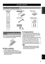
...the packaging carefully as alkaline and manganese batteries) together. I Notes on batteries • Change the batteries periodically. • Do not use different types of batteries (such as these conditions, change all of them immediately. model only) Installing Batteries in the Remote Control Insert... STARTED Checking the Package Contents Check your package to make sure it come into contact with new ones. • Do not use old batteries together with clothing, etc. Avoid touching the leaked material or letting it has the following items. Remote control Manganese ...
...the packaging carefully as alkaline and manganese batteries) together. I Notes on batteries • Change the batteries periodically. • Do not use different types of batteries (such as these conditions, change all of them immediately. model only) Installing Batteries in the Remote Control Insert... STARTED Checking the Package Contents Check your package to make sure it come into contact with new ones. • Do not use old batteries together with clothing, etc. Avoid touching the leaked material or letting it has the following items. Remote control Manganese ...
Owner's Manual
Page 6
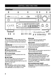
... input source. 5 INPUT l / h Selects the input source (DVD, D-TV/LD, CBL/SAT, VCR 1, VCR 2/DVR, V-AUX, PHONO, CD, TUNER, CD-R, MD/TAPE) you do not use a subwoofer. This does not affect the REC OUT level. 7 6CH INPUT Selects the source connected to 5-second delay before this unit can reproduce sound. Standby..., TREBLE, and BASS EXTENSION are bypassed, eliminating any alteration of all audio channels. This boost is set to SMALL and "1D LFE/ BASS OUT" is useful if you want to listen to or watch. 6 VOLUME Controls the output level of the original signal. 4
... input source. 5 INPUT l / h Selects the input source (DVD, D-TV/LD, CBL/SAT, VCR 1, VCR 2/DVR, V-AUX, PHONO, CD, TUNER, CD-R, MD/TAPE) you do not use a subwoofer. This does not affect the REC OUT level. 7 6CH INPUT Selects the source connected to 5-second delay before this unit can reproduce sound. Standby..., TREBLE, and BASS EXTENSION are bypassed, eliminating any alteration of all audio channels. This boost is set to SMALL and "1D LFE/ BASS OUT" is useful if you want to listen to or watch. 6 VOLUME Controls the output level of the original signal. 4

Owner's Manual
Page 7
...button is received, press this button to tune in the PTY SEEK mode. CONTROLS AND FUNCTIONS a RDS MODE/FREQ When an RDS station is also used to change the display mode among the PS mode, PTY mode, RT mode, CT mode (if the station offers those RDS data services) and/or...station number 1 to 8 when the colon (:) appears next to start automatic preset tuning. y VIDEO AUX jacks Inputs audio and video signals from these speakers by using EFFECT, all Dolby Digital and DTS audio signals except for more than 3 seconds to the band indication on the front panel display. To reproduce source...
...button is received, press this button to tune in the PTY SEEK mode. CONTROLS AND FUNCTIONS a RDS MODE/FREQ When an RDS station is also used to change the display mode among the PS mode, PTY mode, RT mode, CT mode (if the station offers those RDS data services) and/or...station number 1 to 8 when the colon (:) appears next to start automatic preset tuning. y VIDEO AUX jacks Inputs audio and video signals from these speakers by using EFFECT, all Dolby Digital and DTS audio signals except for more than 3 seconds to the band indication on the front panel display. To reproduce source...
Owner's Manual
Page 8
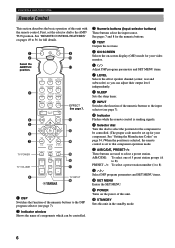
... this dial to select the position for full details. 1 9 2 0 Select the AMP/TUN q position. 3 4 5 6 7 TV POWER TV VOLUME 8 EFFECT See page 7. w A/B/C/D/E, PRESET-/+ These buttons are used to select a preset station.
... this dial to select the position for full details. 1 9 2 0 Select the AMP/TUN q position. 3 4 5 6 7 TV POWER TV VOLUME 8 EFFECT See page 7. w A/B/C/D/E, PRESET-/+ These buttons are used to select a preset station.

Owner's Manual
Page 10
... remote control in the following types of conditions: - or - in the AMP/TUN (or DSP/TUN) position. CONTROLS AND FUNCTIONS I When selecting a preset station number Using the Remote Control STANDBY /ON TUNER DSP D I G I TA L D I G I Handling the remote control • Do not spill water or other liquids on the main unit during...
... remote control in the following types of conditions: - or - in the AMP/TUN (or DSP/TUN) position. CONTROLS AND FUNCTIONS I When selecting a preset station number Using the Remote Control STANDBY /ON TUNER DSP D I G I TA L D I G I Handling the remote control • Do not spill water or other liquids on the main unit during...

Owner's Manual
Page 11
... the "EON" indicator lights up when this unit is reproducing. a SLEEP indicator Lights up while the sleep timer is on . 2 VIRTUAL indicator Lights up when using Virtual CINEMA DSP (see page 29). 3 g and o indicators Light up when the builtin Dolby Digital decoder is in the automatic tuning mode. " g " lights up according...
... the "EON" indicator lights up when this unit is reproducing. a SLEEP indicator Lights up while the sleep timer is on . 2 VIRTUAL indicator Lights up when using Virtual CINEMA DSP (see page 29). 3 g and o indicators Light up when the builtin Dolby Digital decoder is in the automatic tuning mode. " g " lights up according...

Owner's Manual
Page 12
...MAIN A OR B: 8 MIN. /SPEAKER A + B:16 MIN. /SPEAKER CENTER : 8 MIN. /SPEAKER REAR : 8 MIN. /SPEAKER R REAR (SURROUND) L As this terminal is used for an examination in the standby mode before you change the setting of this terminal. 1 DIGITAL INPUT jacks 2 DIGITAL OUTPUT jacks 3 Antenna input terminals See...6CH INPUT jacks See pages 13 and 18 for connection information. (Europe model) q 8 AC power cord Connect to a power outlet. 9 AC OUTLET(S) Use these outlets to supply power to your other A/V components (see page 19). 10 SPEAKERS - - - - + L OUTPUT MAIN R L MAINS AC ...
...MAIN A OR B: 8 MIN. /SPEAKER A + B:16 MIN. /SPEAKER CENTER : 8 MIN. /SPEAKER REAR : 8 MIN. /SPEAKER R REAR (SURROUND) L As this terminal is used for an examination in the standby mode before you change the setting of this terminal. 1 DIGITAL INPUT jacks 2 DIGITAL OUTPUT jacks 3 Antenna input terminals See...6CH INPUT jacks See pages 13 and 18 for connection information. (Europe model) q 8 AC power cord Connect to a power outlet. 9 AC OUTLET(S) Use these outlets to supply power to your other A/V components (see page 19). 10 SPEAKERS - - - - + L OUTPUT MAIN R L MAINS AC ...
Owner's Manual
Page 13
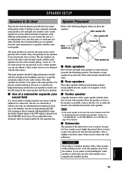
... English 11 If for the center sounds (dialog, vocals, etc.). The other types of sound may not shift smoothly. The YAMAHA Active Servo Processing Subwoofer System is set to NONE (see page 41 for natural and lively bass reproduction. I Center speaker Align... The main speakers are obtained with a video monitor. Main speaker (R) Rear speaker (R) Main speaker (L) Subwoofer 1.8 m Center speaker Rear speaker (L) I Use of a subwoofer expands your sound field It is effective not only for reinforcing bass frequencies from your listening position, facing slightly inwards, nearly 1.8 m ...
... English 11 If for the center sounds (dialog, vocals, etc.). The other types of sound may not shift smoothly. The YAMAHA Active Servo Processing Subwoofer System is set to NONE (see page 41 for natural and lively bass reproduction. I Center speaker Align... The main speakers are obtained with a video monitor. Main speaker (R) Rear speaker (R) Main speaker (L) Subwoofer 1.8 m Center speaker Rear speaker (L) I Use of a subwoofer expands your sound field It is effective not only for reinforcing bass frequencies from your listening position, facing slightly inwards, nearly 1.8 m ...
Owner's Manual
Page 14
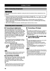
Do not discard the cap. If you have a turntable with the same number labels as !, #, $ etc. YAMAHA applies this labeling system to all connections are not using this unit. About the dust protection cap Pull out the cap from the optical jack before you are made correctly, that does not... not electrically ground the turntable. You can designate the input for each component to be connected to this unit. • When you connect other YAMAHA audio components (such as a CD or DVD are available for connecting a turntable with an MM or high-output MC cartridge. If the power...
Do not discard the cap. If you have a turntable with the same number labels as !, #, $ etc. YAMAHA applies this labeling system to all connections are not using this unit. About the dust protection cap Pull out the cap from the optical jack before you are made correctly, that does not... not electrically ground the turntable. You can designate the input for each component to be connected to this unit. • When you connect other YAMAHA audio components (such as a CD or DVD are available for connecting a turntable with an MM or high-output MC cartridge. If the power...
Owner's Manual
Page 16
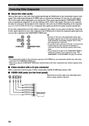
... output through the corresponding composite video, S-video, and component jacks, respectively. • If you make composite video connections. Notes • Use a commercially available S-video cable when connecting to the S VIDEO jack, and commercially available video cables when connecting to the COMPONENT VIDEO jacks....jacks, check the details in picture reproduction. If your video component has an S-video output or component video output, you are used to the COMPONENT VIDEO jacks. Connect the S-video signal output jack on your video component to this unit. I Video monitor...
... output through the corresponding composite video, S-video, and component jacks, respectively. • If you make composite video connections. Notes • Use a commercially available S-video cable when connecting to the S VIDEO jack, and commercially available video cables when connecting to the COMPONENT VIDEO jacks....jacks, check the details in picture reproduction. If your video component has an S-video output or component video output, you are used to the COMPONENT VIDEO jacks. Connect the S-video signal output jack on your video component to this unit. I Video monitor...

Owner's Manual
Page 17
... the Dolby Digital RF signal output of your LD player has an Dolby Digital RF signal output jack, connect it to the COAXIAL jack by using "7 I/O ASSIGNMENT" on the SET MENU (see page 44). RF OPTICAL OUTPUT OUTPUT LD player COMPONENT AUDIO OUTPUT OUTPUT TV/digital TV or LD player OPTICAL...
... the Dolby Digital RF signal output of your LD player has an Dolby Digital RF signal output jack, connect it to the COAXIAL jack by using "7 I/O ASSIGNMENT" on the SET MENU (see page 44). RF OPTICAL OUTPUT OUTPUT LD player COMPONENT AUDIO OUTPUT OUTPUT TV/digital TV or LD player OPTICAL...

Owner's Manual
Page 18
... the sound will be heard from each terminal. 3 Tighten the knob to prevent short circuits. If you finish connecting your configuration after you use only one bare wire into the hole in your speakers. I CENTER SPEAKER terminals A center speaker can be connected to these terminals. I ... the bare speaker wires touch each other and do not let them touch any metal part of insulated cables running side by side. CAUTION • Use speakers with a stripe, groove or ridge. 1 Remove approx. 10 mm (3/8") of insulation from the speakers, and if the polarity of the MAIN ...
... the sound will be heard from each terminal. 3 Tighten the knob to prevent short circuits. If you finish connecting your configuration after you use only one bare wire into the hole in your speakers. I CENTER SPEAKER terminals A center speaker can be connected to these terminals. I ... the bare speaker wires touch each other and do not let them touch any metal part of insulated cables running side by side. CAUTION • Use speakers with a stripe, groove or ridge. 1 Remove approx. 10 mm (3/8") of insulation from the speakers, and if the polarity of the MAIN ...

Owner's Manual
Page 20
... or DTS is decoded are also directed if they are affected by the BASS, TREBLE and BASS EXTENSION settings. 2 SUBWOOFER jack When using a subwoofer with built-in amplifier, including the YAMAHA Active Servo Processing Subwoofer System, connect the input jack of the subwoofer system to this jack. OUTPUT 1 MAIN R L SUB WOOFER 2 Connecting...
... or DTS is decoded are also directed if they are affected by the BASS, TREBLE and BASS EXTENSION settings. 2 SUBWOOFER jack When using a subwoofer with built-in amplifier, including the YAMAHA Active Servo Processing Subwoofer System, connect the input jack of the subwoofer system to this jack. OUTPUT 1 MAIN R L SUB WOOFER 2 Connecting...

Owner's Manual
Page 21
...B:16 MIN. /SPEAKER CENTER : 8 MIN. /SPEAKER REAR : 8 MIN. /SPEAKER To AC outlet Europe model 2 OUTLETS U.K. These outlets will not use one set of main speakers, the impedance of each speaker must be 8 Ω or higher. If so, slide the switch to the AC OUTLET(S) ... 8 MIN. /SPEAKER A + B:16 MIN. /SPEAKER CENTER : 8 MIN. /SPEAKER REAR : 8 MIN. /SPEAKER Right Main Center Rear If you use two sets of main speakers, the impedance of time. The impedance must be 8 Ω or higher. INTRODUCTION PREPARATION BASIC OPERAIONT IMPEDANCE SELECTOR Switch CONNECTIONS WARNING...
...B:16 MIN. /SPEAKER CENTER : 8 MIN. /SPEAKER REAR : 8 MIN. /SPEAKER To AC outlet Europe model 2 OUTLETS U.K. These outlets will not use one set of main speakers, the impedance of each speaker must be 8 Ω or higher. If so, slide the switch to the AC OUTLET(S) ... 8 MIN. /SPEAKER A + B:16 MIN. /SPEAKER CENTER : 8 MIN. /SPEAKER REAR : 8 MIN. /SPEAKER Right Main Center Rear If you use two sets of main speakers, the impedance of time. The impedance must be 8 Ω or higher. INTRODUCTION PREPARATION BASIC OPERAIONT IMPEDANCE SELECTOR Switch CONNECTIONS WARNING...

Owner's Manual
Page 22
... operation information for this unit on the S-video signal. If you display the SET MENU and DSP program parameter settings on a monitor, it is by using "14 DISPLAY SET" on both the S-video and composite video signals. • If your video monitor to operations appear on the monitor except those of...
... operation information for this unit on the S-video signal. If you display the SET MENU and DSP program parameter settings on a monitor, it is by using "14 DISPLAY SET" on both the S-video and composite video signals. • If your video monitor to operations appear on the monitor except those of...

Owner's Manual
Page 24
... CENTER) LEFT SURROUND RIGHT SURROUND (TEST L SUR.) (TEST R SUR.) 22 This is made at your listening position to check if the adjustments are using two sets of the digital sound field processor, the Dolby Pro Logic decoder, Dolby Digital decoder and DTS decoder. at the listening position will be... Press TEST to output the test tone. 2 Press SPEAKERS A or B to select the main speakers to be the same from the PHONES jack when using the test tone generator. When this unit, be sure to unplug the headphones from each speaker output level should be made , the output level heard...
... CENTER) LEFT SURROUND RIGHT SURROUND (TEST L SUR.) (TEST R SUR.) 22 This is made at your listening position to check if the adjustments are using two sets of the digital sound field processor, the Dolby Pro Logic decoder, Dolby Digital decoder and DTS decoder. at the listening position will be... Press TEST to output the test tone. 2 Press SPEAKERS A or B to select the main speakers to be the same from the PHONES jack when using the test tone generator. When this unit, be sure to unplug the headphones from each speaker output level should be made , the output level heard...

Owner's Manual
Page 25
... output level coming from the selected speaker. 6 When the adjustment is convenient for the center and rear speakers again. 5 Press j / i repeatedly to be adjusted by using "5 CENTER GEQ" on the video monitor. Note • If the test tone cannot be heard, turn down the volume, set the unit in the reverse...
... output level coming from the selected speaker. 6 When the adjustment is convenient for the center and rear speakers again. 5 Press j / i repeatedly to be adjusted by using "5 CENTER GEQ" on the video monitor. Note • If the test tone cannot be heard, turn down the volume, set the unit in the reverse...


