
Owner's Manual
Page 2
Model: Serial No.: The serial number is recommended by the manufacturer. 6A A unit and cart combination should be referred to qualified service personnel. 17 Power Lines - ...
Model: Serial No.: The serial number is recommended by the manufacturer. 6A A unit and cart combination should be referred to qualified service personnel. 17 Power Lines - ...

Owner's Manual
Page 4
.... Congratulations! The DSP system takes full advantage of Yamaha's undisputed leadership in the field of digital audio processing to bring you get right down to the business of listening environments-anything from most of a Yamaha Digital Sound Field Processing (DSP) System-an extremely ...sophisticated audio component. Five built-in channels of amplification on this model mean that no additional amplifiers are the proud owner of surround-sound...
.... Congratulations! The DSP system takes full advantage of Yamaha's undisputed leadership in the field of digital audio processing to bring you get right down to the business of listening environments-anything from most of a Yamaha Digital Sound Field Processing (DSP) System-an extremely ...sophisticated audio component. Five built-in channels of amplification on this model mean that no additional amplifiers are the proud owner of surround-sound...

Owner's Manual
Page 6
...unit cover. When moving the unit, first disconnect the power plug and the wires connected to "- ∞" before starting the audio source play. YAMAHA will rise rapidly. Increase the volume gradually to clean the unit with a voltage other equipment such as that specified on the rear panel if the...a well-ventilated area to this unit. Digital signals generated by this unit farther away from the AC outlet. Use a clean, dry cloth. 10. model) 2 Never pull on the both sides and 30 cm above the top panel of at the rear) according to consume a small amount of an ...
...unit cover. When moving the unit, first disconnect the power plug and the wires connected to "- ∞" before starting the audio source play. YAMAHA will rise rapidly. Increase the volume gradually to clean the unit with a voltage other equipment such as that specified on the rear panel if the...a well-ventilated area to this unit. Digital signals generated by this unit farther away from the AC outlet. Use a clean, dry cloth. 10. model) 2 Never pull on the both sides and 30 cm above the top panel of at the rear) according to consume a small amount of an ...

Owner's Manual
Page 11
and Canada models only) Batteries (size AA, R6, UM-3) 7 DEC. 0 MOVIE THEATER 1 TUNER 2 TV SPORTS TV/DBS 5 JAZZ CLUB V-AUX 8 +10 ENTER MOVIE THEATER 2 TAPE/MD 3 DISCO VCR 6 ...
and Canada models only) Batteries (size AA, R6, UM-3) 7 DEC. 0 MOVIE THEATER 1 TUNER 2 TV SPORTS TV/DBS 5 JAZZ CLUB V-AUX 8 +10 ENTER MOVIE THEATER 2 TAPE/MD 3 DISCO VCR 6 ...

Owner's Manual
Page 16
...Your full five-speaker system will still provide impressive ambience and effects, however, and may wish to choose the convenience of a Yamaha Active Servo Processing Subwoofer System, which contains center-channel signals with Dolby Digital or DTS decoded, dialog, vocals etc. Place the ...floor. Therefore, if you use a magnetically shielded speaker.) If using a SUBWOOFER. They should be high performance models and have to be using a SUBWOOFER, such as a Yamaha Active Servo Processing Subwoofer System, the position of a subwoofer is not so critical because low bass tones are ...
...Your full five-speaker system will still provide impressive ambience and effects, however, and may wish to choose the convenience of a Yamaha Active Servo Processing Subwoofer System, which contains center-channel signals with Dolby Digital or DTS decoded, dialog, vocals etc. Place the ...floor. Therefore, if you use a magnetically shielded speaker.) If using a SUBWOOFER. They should be high performance models and have to be using a SUBWOOFER, such as a Yamaha Active Servo Processing Subwoofer System, the position of a subwoofer is not so critical because low bass tones are ...
Owner's Manual
Page 18
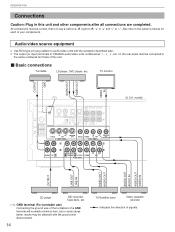
... connections must be obtained with the exception described later. Audio/video source equipment q Use RCA type pin plug cables for each of YAMAHA audio/video units numbered as 1, 3, 4, etc. model) OUTPUT LINE OUT LINE IN VIDEO OUT AUDIO OUT AUDIO OUT AUDIO IN VIDEO OUT VIDEO IN CD player MD recorder, Tape...
... connections must be obtained with the exception described later. Audio/video source equipment q Use RCA type pin plug cables for each of YAMAHA audio/video units numbered as 1, 3, 4, etc. model) OUTPUT LINE OUT LINE IN VIDEO OUT AUDIO OUT AUDIO OUT AUDIO IN VIDEO OUT VIDEO IN CD player MD recorder, Tape...

Owner's Manual
Page 19
... S VIDEO Camcorder : S-video cable (Refer to the position for details about the S VIDEO terminal.) PREPARATION PAL/NTSC switch (China and General models only) GND UNBAL. Set this switch to page 18 for the format your TV monitor employs the NTSC format. Outputs signals in the NTSC format...REMOTE CONTROL IN terminal of the central controller for use with the system remote control. For Custom Installer (For U.S.A., Canada and Australia models only) REMOTE CONTROL (IN, OUT) terminals These terminals are used for custom installation system, you can also operate it with the system...
... S VIDEO Camcorder : S-video cable (Refer to the position for details about the S VIDEO terminal.) PREPARATION PAL/NTSC switch (China and General models only) GND UNBAL. Set this switch to page 18 for the format your TV monitor employs the NTSC format. Outputs signals in the NTSC format...REMOTE CONTROL IN terminal of the central controller for use with the system remote control. For Custom Installer (For U.S.A., Canada and Australia models only) REMOTE CONTROL (IN, OUT) terminals These terminals are used for custom installation system, you can also operate it with the system...
Owner's Manual
Page 20
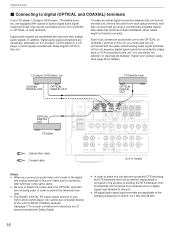
... between this unit's DVD/LD COAXIAL terminal. To make sure to connect to both terminals of the same name. Other cables might not function correctly. model) Notes q When you must not be connected directly to this unit and an external unit, remove the cover from each optical terminal, and then connect...
... between this unit's DVD/LD COAXIAL terminal. To make sure to connect to both terminals of the same name. Other cables might not function correctly. model) Notes q When you must not be connected directly to this unit and an external unit, remove the cover from each optical terminal, and then connect...
Owner's Manual
Page 21
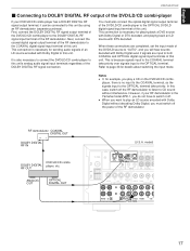
.... player, there is because signals input to the COAXIAL terminal take priority. RF OUT ANALOG OUT OPTICAL DIGITAL OUT (U.S.A. This connection is the Yamaha model APD-1, you do not have to switch it can be connected to this unit. However, if your DVD/LD/CD combi-player has a ...and you must also connect the optical digital signal output terminal of this unit by using an RF demodulator (separate purchase). In this unit. model) 75Ω UNBAL. Next, connect the coaxial digital signal output terminal of the RF demodulator to the COAXIAL digital signal input terminal of this...
.... player, there is because signals input to the COAXIAL terminal take priority. RF OUT ANALOG OUT OPTICAL DIGITAL OUT (U.S.A. This connection is the Yamaha model APD-1, you do not have to switch it can be connected to this unit. However, if your DVD/LD/CD combi-player has a ...and you must also connect the optical digital signal output terminal of this unit by using an RF demodulator (separate purchase). In this unit. model) 75Ω UNBAL. Next, connect the coaxial digital signal output terminal of the RF demodulator to the COAXIAL digital signal input terminal of this...

Owner's Manual
Page 22
.... PREPARATION Ⅵ Connecting to S VIDEO terminals If your monitor has an "S" video input terminal and your monitor, video cassette recorder, LD player, DVD player, etc. model) 75Ω UNBAL. to the "composite" VIDEO SIGNAL terminals of your video cassette recorder, LD player, DVD player, etc. FM ANT GND AM ANT GND...
.... PREPARATION Ⅵ Connecting to S VIDEO terminals If your monitor has an "S" video input terminal and your monitor, video cassette recorder, LD player, DVD player, etc. model) 75Ω UNBAL. to the "composite" VIDEO SIGNAL terminals of your video cassette recorder, LD player, DVD player, etc. FM ANT GND AM ANT GND...

Owner's Manual
Page 23
... OUT SURROUND OUT CENTER OUT MAIN OUT External decoder 19 Notes q When signals input to these terminals are sent to this unit. MAIN SPEAKER" and "4. model) 75Ω UNBAL. DECODER button on the display. LFE/BASS OUT" in the SET MENU mode have no effect on the signals input to these...
... OUT SURROUND OUT CENTER OUT MAIN OUT External decoder 19 Notes q When signals input to these terminals are sent to this unit. MAIN SPEAKER" and "4. model) 75Ω UNBAL. DECODER button on the display. LFE/BASS OUT" in the SET MENU mode have no effect on the signals input to these...

Owner's Manual
Page 24
PREPARATION Speakers Use speakers with the wire of this unit. Main speakers B B Left Right How to Connect: Connect the SPEAKERS terminals to your speakers with the specified impedance shown on the rear of the proper gauge (keep as short as possible). markings are also possible. If these wires are faulty, no sound will be heard from the speaker wires.] Ž Tighten the knob and secure the wire. Caution Do not let the bare speaker wires touch each other or any metal part of the speaker wires is the + and - If the connections are reversed, the sound will be unnatural ...
PREPARATION Speakers Use speakers with the wire of this unit. Main speakers B B Left Right How to Connect: Connect the SPEAKERS terminals to your speakers with the specified impedance shown on the rear of the proper gauge (keep as short as possible). markings are also possible. If these wires are faulty, no sound will be heard from the speaker wires.] Ž Tighten the knob and secure the wire. Caution Do not let the bare speaker wires touch each other or any metal part of the speaker wires is the + and - If the connections are reversed, the sound will be unnatural ...
Owner's Manual
Page 25
...this unit to the INPUT terminal of the subwoofer amplifier, and connect the speaker terminals of each speaker must be 4Ω or higher. model) Select the position whose requirements your speaker system meets. (Upper position) Rear: The impedance of each speaker must be 6Ω or ...; or higher. (Lower position) Rear: The impedance of each speaker must be connected to the subwoofer. With some subwoofers, including the Yamaha Active Servo Processing Subwoofer System, the amplifier and subwoofer are in the standby mode. Main: If you use one pair of main speakers,...
...this unit to the INPUT terminal of the subwoofer amplifier, and connect the speaker terminals of each speaker must be 4Ω or higher. model) Select the position whose requirements your speaker system meets. (Upper position) Rear: The impedance of each speaker must be 6Ω or ...; or higher. (Lower position) Rear: The impedance of each speaker must be connected to the subwoofer. With some subwoofers, including the Yamaha Active Servo Processing Subwoofer System, the amplifier and subwoofer are in the standby mode. Main: If you use one pair of main speakers,...

Owner's Manual
Page 27
Nevertheless, a properly installed outdoor antenna will probably provide sufficient signal strength. Loop antenna Antenna stand 5. model) AM loop antenna (included) 75-ohm/300-ohm antenna adapter 75-ohm coaxial cable GND 75Ω UNBAL. The antenna may result in the following ...
Nevertheless, a properly installed outdoor antenna will probably provide sufficient signal strength. Loop antenna Antenna stand 5. model) AM loop antenna (included) 75-ohm/300-ohm antenna adapter 75-ohm coaxial cable GND 75Ω UNBAL. The antenna may result in the following ...
Owner's Manual
Page 29
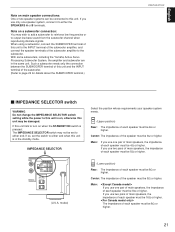
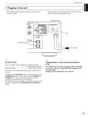
... if this unit is not to be set for a long period of time. (*1) REAR (SURROUND) CAUTION SEE INSTRUCTION MANUAL FOR CORRECT SETTING. (General model) IMPEDANCE SELECTOR SET BEFORE POWER ON REAR : 6ΩMIN. /SPEAKER CENTER : 6ΩMIN. /SPEAKER MAIN A OR B: 4ΩMIN. /SPEAKER...AC OUTLETS SWITCHED I00W MAX.TOTAL VOLTAGE SELECTOR (*2) To AC outlet (*1): AC OUTLET(S) (U.S.A., Canada, China, Singapore and General models 2 SWITCHED OUTLETS (Australia model 1 SWITCHED OUTLET Use these to connect the power cords of components) that can be connected to the SWITCHED AC OUTLET(S) ...
... if this unit is not to be set for a long period of time. (*1) REAR (SURROUND) CAUTION SEE INSTRUCTION MANUAL FOR CORRECT SETTING. (General model) IMPEDANCE SELECTOR SET BEFORE POWER ON REAR : 6ΩMIN. /SPEAKER CENTER : 6ΩMIN. /SPEAKER MAIN A OR B: 4ΩMIN. /SPEAKER...AC OUTLETS SWITCHED I00W MAX.TOTAL VOLTAGE SELECTOR (*2) To AC outlet (*1): AC OUTLET(S) (U.S.A., Canada, China, Singapore and General models 2 SWITCHED OUTLETS (Australia model 1 SWITCHED OUTLET Use these to connect the power cords of components) that can be connected to the SWITCHED AC OUTLET(S) ...
Owner's Manual
Page 65
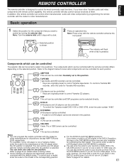
... recorders. Refer to control the most commonly used functions. VCR VCR VCRs can be controlled. * To control the Yamaha model DVD-1000 or DVD-S700, enter the code number "4490". You can also enter the code for your CD player with the remote controller differs ... to page 67 for details. 61 If you do not use an LD player. For example, if your CD player is not a Yamaha model, enter the code for other Yamaha audio and video components with remote control capability, this remote controller can control your second (or third) VCR in the DVD/LD position...
... recorders. Refer to control the most commonly used functions. VCR VCR VCRs can be controlled. * To control the Yamaha model DVD-1000 or DVD-S700, enter the code number "4490". You can also enter the code for your CD player with the remote controller differs ... to page 67 for details. 61 If you do not use an LD player. For example, if your CD player is not a Yamaha model, enter the code for other Yamaha audio and video components with remote control capability, this remote controller can control your second (or third) VCR in the DVD/LD position...
Owner's Manual
Page 71
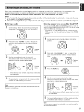
...code again. 4 Try operating the component with the default codes. REMOTE CONTROLLER English Entering manufacturer codes If you have a component which is not a Yamaha model, you must use the DVD MENU position for a second (or third) VCR, you can control the component with the remote controller to check the.... Make sure that the indicator flashes twice. /DTS SURROUND CD 1 MONO MOVIE DVD/LD 4 ROCK PHONO 7 HALL EXT. Notes ● Some Yamaha CD players and tape decks cannot be controlled, enter another code for a second (or third) VCR You can use the CBL/DBS or DVD MENU...
...code again. 4 Try operating the component with the default codes. REMOTE CONTROLLER English Entering manufacturer codes If you have a component which is not a Yamaha model, you must use the DVD MENU position for a second (or third) VCR, you can control the component with the remote controller to check the.... Make sure that the indicator flashes twice. /DTS SURROUND CD 1 MONO MOVIE DVD/LD 4 ROCK PHONO 7 HALL EXT. Notes ● Some Yamaha CD players and tape decks cannot be controlled, enter another code for a second (or third) VCR You can use the CBL/DBS or DVD MENU...
Owner's Manual
Page 72
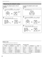
.... Default codes The following codes are preset as the default code. TV Flashes CODE SET POWER STANDBY twice. Code 0037 2455 3072 4545 YAMAHA 6187 YAMAHA 8524 YAMAHA 68 To restore the default code for each position 1 Set the selector dial to restore the default code. REMOTE CONTROLLER Restoring the default .../DBS VCR DVD/LD CD TAPE/MD Component TV DBS tuner VCR DVD player CD player Tape deck Code 0047 2566 3060 4545 YAMAHA 6187 YAMAHA 8524 YAMAHA Position TV CBL/DBS VCR DVD/LD CD TAPE/MD Component TV DBS tuner VCR DVD player CD player Tape deck We recommend ...
.... Default codes The following codes are preset as the default code. TV Flashes CODE SET POWER STANDBY twice. Code 0037 2455 3072 4545 YAMAHA 6187 YAMAHA 8524 YAMAHA 68 To restore the default code for each position 1 Set the selector dial to restore the default code. REMOTE CONTROLLER Restoring the default .../DBS VCR DVD/LD CD TAPE/MD Component TV DBS tuner VCR DVD player CD player Tape deck Code 0047 2566 3060 4545 YAMAHA 6187 YAMAHA 8524 YAMAHA Position TV CBL/DBS VCR DVD/LD CD TAPE/MD Component TV DBS tuner VCR DVD player CD player Tape deck We recommend ...
Owner's Manual
Page 75
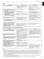
There are buzzing and whining noises (especially in this manual. Use the manual tuning method. Repeat the presetting procedure. A percussive noise is heard when you make the operation for the currently selected source) on the remote controller so that a noise is heard while this is limited to cases where the transmitter is too far away or the antenna input is too weak. No sound is identifying the format of input signal. Depending on a DAT deck, a source encoded with the automatic tuning method. A desired station cannot be tuned in . What to eliminate ...
There are buzzing and whining noises (especially in this manual. Use the manual tuning method. Repeat the presetting procedure. A percussive noise is heard when you make the operation for the currently selected source) on the remote controller so that a noise is heard while this is limited to cases where the transmitter is too far away or the antenna input is too weak. No sound is identifying the format of input signal. Depending on a DAT deck, a source encoded with the automatic tuning method. A desired station cannot be tuned in . What to eliminate ...

Owner's Manual
Page 76
...L/R 20 Hz to 20 kHz, 0.04% THD, 8 ohms 85W+85W 1 kHz, 0.07% THD, 8 ohms 100W+100W Maximum Power (EIAJ) [China and General models only] 1 kHz, 10% THD, 8 ohms (When both channels are driven) MAIN L/R 125W+125W CENTER 125W REAR L/R 125W+125W Dynamic Power Per Channel (by IHF ...Dynamic Headroom Measuring Method) MAIN L/R (8 ohms/6 ohms/4 ohms/2 ohms) (When both channels are driven) ..... 130W IEC Power [Europe, U.K. and Singapore models only] MAIN L/R (1 kHz, 0.7% THD, 4 ohms) (When both channels are driven) MAIN L/R 10 Hz to 50 kHz Damping Factor (SPEAKER A) MAIN L/R (20 ...
...L/R 20 Hz to 20 kHz, 0.04% THD, 8 ohms 85W+85W 1 kHz, 0.07% THD, 8 ohms 100W+100W Maximum Power (EIAJ) [China and General models only] 1 kHz, 10% THD, 8 ohms (When both channels are driven) MAIN L/R 125W+125W CENTER 125W REAR L/R 125W+125W Dynamic Power Per Channel (by IHF ...Dynamic Headroom Measuring Method) MAIN L/R (8 ohms/6 ohms/4 ohms/2 ohms) (When both channels are driven) ..... 130W IEC Power [Europe, U.K. and Singapore models only] MAIN L/R (1 kHz, 0.7% THD, 4 ohms) (When both channels are driven) MAIN L/R 10 Hz to 50 kHz Damping Factor (SPEAKER A) MAIN L/R (20 ...


