

Owner's Manual
Page 3
... be the source of your equipment by playing it is being affected by Yamaha may cause interference harmful to the operation of cable entry as to avoid prolonged exposure from excessive volume levels. This equipment generates/uses radio frequencies and, if not installed and used . If the antenna lead-in is 300 ohm ribbon lead, change the lead-in the users manual, may void your use only high...
... be the source of your equipment by playing it is being affected by Yamaha may cause interference harmful to the operation of cable entry as to avoid prolonged exposure from excessive volume levels. This equipment generates/uses radio frequencies and, if not installed and used . If the antenna lead-in is 300 ohm ribbon lead, change the lead-in the users manual, may void your use only high...
Owner's Manual
Page 5
... Using the Test Tone (TEST DOLBY SUR 21 BASIC OPERATION BASIC PLAYBACK 23 Input Modes and Indications 25 Selecting a Sound Field Program 27 Normal Stereo Reproduction 28 TUNING 29 Connecting the Antennas 29 Automatic (or Manual) Tuning 30 Presetting Stations 31 Tuning in to a Preset Station 32 Exchanging Preset Stations 33 BASIC RECORDING 34 ADVANCED OPERATION SET MENU 35 Adjusting the Items on the SET MENU 35 1 SPEAKER SET (speaker mode settings 36 2 L/R BALANCE (balance of the Selector Dial 45 Controlling the Components Connected to This Unit 45 Button Names and Functions...
... Using the Test Tone (TEST DOLBY SUR 21 BASIC OPERATION BASIC PLAYBACK 23 Input Modes and Indications 25 Selecting a Sound Field Program 27 Normal Stereo Reproduction 28 TUNING 29 Connecting the Antennas 29 Automatic (or Manual) Tuning 30 Presetting Stations 31 Tuning in to a Preset Station 32 Exchanging Preset Stations 33 BASIC RECORDING 34 ADVANCED OPERATION SET MENU 35 Adjusting the Items on the SET MENU 35 1 SPEAKER SET (speaker mode settings 36 2 L/R BALANCE (balance of the Selector Dial 45 Controlling the Components Connected to This Unit 45 Button Names and Functions...

Owner's Manual
Page 6
... Speaker Balance Adjustment x 6-Channel External Decoder Input for Other Future Formats x BASS EXTENSION Button for Reinforcing Bass Response x On Screen Display Function Helpful in Controlling This Unit x S Video Signal Input/Output Capability x Component Video Input/Output Capability x Optical and Coaxial Digital Audio Signal Jacks x Sleep Timer x Remote Control with Preset Manufacturer Codes • y indicates a tip for your operation. • Some operations can be performed by using either the buttons on the main unit or on the remote control is given in parentheses in 5-Channel Power...
... Speaker Balance Adjustment x 6-Channel External Decoder Input for Other Future Formats x BASS EXTENSION Button for Reinforcing Bass Response x On Screen Display Function Helpful in Controlling This Unit x S Video Signal Input/Output Capability x Component Video Input/Output Capability x Optical and Coaxial Digital Audio Signal Jacks x Sleep Timer x Remote Control with Preset Manufacturer Codes • y indicates a tip for your operation. • Some operations can be performed by using either the buttons on the main unit or on the remote control is given in parentheses in 5-Channel Power...

Owner's Manual
Page 8
... channels. Standby mode In this mode, this unit consumes a small amount of power to receive infrared-signals from the remote control. 2 Remote control sensor Receives signals from the remote control. 3 Front panel display Shows information about the operational status of this unit can reproduce sound. Front Panel 1 CONTROLS AND FUNCTIONS 2 3 45 6 STANDBY /ON D I G I TA L SURROUND BASS EXTENSION BASS TREBLE ON OFF -+ -+ SPEAKERS A B ON OFF D I G I TA L VOLUME EFFECT DSP PROGRAM PRESET /TUNING FM/AM MEMORY TUNING MODE EDIT PHONES S VIDEO VIDEO L AUDIO R OPTICAL...
... channels. Standby mode In this mode, this unit consumes a small amount of power to receive infrared-signals from the remote control. 2 Remote control sensor Receives signals from the remote control. 3 Front panel display Shows information about the operational status of this unit can reproduce sound. Front Panel 1 CONTROLS AND FUNCTIONS 2 3 45 6 STANDBY /ON D I G I TA L SURROUND BASS EXTENSION BASS TREBLE ON OFF -+ -+ SPEAKERS A B ON OFF D I G I TA L VOLUME EFFECT DSP PROGRAM PRESET /TUNING FM/AM MEMORY TUNING MODE EDIT PHONES S VIDEO VIDEO L AUDIO R OPTICAL...
Owner's Manual
Page 9
... selecting DSP program. This button is also used to exchange the assignment of these buttons turn off . To select the automatic tuning mode, press this button so that the "AUTO" indicator lights up . When Dolby Digital or DTS signals are output to the main left and right main speakers. To select the manual tuning mode, press this button so that the "AUTO" indicator does not light up on the front panel display again. INTRODUCTION PREPARATION 8 BASS Adjusts the low-frequency response for FM stations...
... selecting DSP program. This button is also used to exchange the assignment of these buttons turn off . To select the automatic tuning mode, press this button so that the "AUTO" indicator lights up . When Dolby Digital or DTS signals are output to the main left and right main speakers. To select the manual tuning mode, press this button so that the "AUTO" indicator does not light up on the front panel display again. INTRODUCTION PREPARATION 8 BASS Adjusts the low-frequency response for FM stations...

Owner's Manual
Page 10
... buttons. 4 6CH INPUT Selects the source connected to the 6CH INPUT jacks. 5 TEST Outputs the test tone. 6 ON SCREEN Selects the on -screen display. 8 LEVEL Selects the effect speaker channel (center, rear and subwoofer) so you can be set up for your video monitor. 7 j / i (-/+) Adjust DSP program parameters and SET MENU items. -/+ is set the selector dial to the AMP/ TUN position. e A/B/C/D/E, PRESET -/+ These buttons are used to 8) r u/d Select DSP program parameters and SET MENU items. t SET MENU Enters the SET MENU. First, set to that component operation mode. u STANDBY Sets...
... buttons. 4 6CH INPUT Selects the source connected to the 6CH INPUT jacks. 5 TEST Outputs the test tone. 6 ON SCREEN Selects the on -screen display. 8 LEVEL Selects the effect speaker channel (center, rear and subwoofer) so you can be set up for your video monitor. 7 j / i (-/+) Adjust DSP program parameters and SET MENU items. -/+ is set the selector dial to the AMP/ TUN position. e A/B/C/D/E, PRESET -/+ These buttons are used to 8) r u/d Select DSP program parameters and SET MENU items. t SET MENU Enters the SET MENU. First, set to that component operation mode. u STANDBY Sets...

Owner's Manual
Page 13
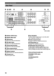
... Dolby Digital decoder is on . INTRODUCTION PREPARATION Front Panel Display CONTROLS AND FUNCTIONS 1 23 4 5 6 7 8 VIRTUAL DIGITAL PRO LOGIC DSP SP PCM AB V-AUX VCR2/DVR VCR 1 D-TV/CBL DOLBY DIGITAL MOVIE THEATER 1 2 PRO LOGIC DTS ENTERTAINMENT DVD MD/CD-R TUNER CD TUNED STEREO AUTO PHONO MEMORY SLEEP dmBs VOLUME 90 q w e rt 1 t indicator Lights up when the built-in DTS decoder is on . 4 Input source indicator Shows the current input source with a cursor. 5 TUNED indicator Lights up when this unit tunes in to a station. 6 STEREO...
... Dolby Digital decoder is on . INTRODUCTION PREPARATION Front Panel Display CONTROLS AND FUNCTIONS 1 23 4 5 6 7 8 VIRTUAL DIGITAL PRO LOGIC DSP SP PCM AB V-AUX VCR2/DVR VCR 1 D-TV/CBL DOLBY DIGITAL MOVIE THEATER 1 2 PRO LOGIC DTS ENTERTAINMENT DVD MD/CD-R TUNER CD TUNED STEREO AUTO PHONO MEMORY SLEEP dmBs VOLUME 90 q w e rt 1 t indicator Lights up when the built-in DTS decoder is on . 4 Input source indicator Shows the current input source with a cursor. 5 TUNED indicator Lights up when this unit tunes in to a station. 6 STEREO...
Owner's Manual
Page 14
.../CR COMPONENT VIDEO B DVD D-TV/CBL IN VCR 1OUT IN V/DCVRR2OUT MONITOR OUT VIDEO CENTER + S VIDEO OPTICAL MD/CD-R R L R SUB WOOFER VIDEO SIGNAL DIGITAL OUTPUT R PHONO CD IN(PLAY) OUT(REC) MD/CD-R DVD D-TV/CBL AUDIO SIGNAL IN OUT VCR 1 IN OUT VCR 2/DVR SUB WOOFER OUTPUT R+ REAR (SURROUND) SPEAKERS - - - - - +L +L 89 AC OUTLETS SWITCHED 100W MAX. q SUBWOOFER jack See page 17 for connection information. VOLTAGE SELECTOR See page 18. 10 TOTAL IMPEDANCE SELECTOR SET BEFORE POWER ON MAIN A OR B: 4 MIN. /SPEAKER A + B: 8 MIN. /SPEAKER CENTER...
.../CR COMPONENT VIDEO B DVD D-TV/CBL IN VCR 1OUT IN V/DCVRR2OUT MONITOR OUT VIDEO CENTER + S VIDEO OPTICAL MD/CD-R R L R SUB WOOFER VIDEO SIGNAL DIGITAL OUTPUT R PHONO CD IN(PLAY) OUT(REC) MD/CD-R DVD D-TV/CBL AUDIO SIGNAL IN OUT VCR 1 IN OUT VCR 2/DVR SUB WOOFER OUTPUT R+ REAR (SURROUND) SPEAKERS - - - - - +L +L 89 AC OUTLETS SWITCHED 100W MAX. q SUBWOOFER jack See page 17 for connection information. VOLTAGE SELECTOR See page 18. 10 TOTAL IMPEDANCE SELECTOR SET BEFORE POWER ON MAIN A OR B: 4 MIN. /SPEAKER A + B: 8 MIN. /SPEAKER CENTER...

Owner's Manual
Page 17
... and right SURROUND and SUBWOOFER) for the main and surround channels. model) COAXIAL OUTPUT C LR LR SURROUND OUTPUT CENTER OUTPUT DIGITAL INPUT CD GND AM ANT GND COAXIAL OPTICAL D-TV/CBL DVD 6CH INPUT MAIN SURROUND CENTER L L MD/CD-R OPTICAL MD/CD-R R L R SUB WOOFER TUNER FM ANT DVD D-TV/CBL 75 UNBAL. DVD D-TV/CBL MONITOR OUT Y PB/CB PR/CR COMPONENT VIDEO IN VCR 1OUT IN V/DCVRR2OUT MONITOR OUT VIDEO VIDEO SIGNAL S VIDEO DIGITAL OUTPUT R PHONO CD IN(PLAY) OUT(REC) MD/CD-R DVD D-TV/CBL AUDIO SIGNAL IN...
... and right SURROUND and SUBWOOFER) for the main and surround channels. model) COAXIAL OUTPUT C LR LR SURROUND OUTPUT CENTER OUTPUT DIGITAL INPUT CD GND AM ANT GND COAXIAL OPTICAL D-TV/CBL DVD 6CH INPUT MAIN SURROUND CENTER L L MD/CD-R OPTICAL MD/CD-R R L R SUB WOOFER TUNER FM ANT DVD D-TV/CBL 75 UNBAL. DVD D-TV/CBL MONITOR OUT Y PB/CB PR/CR COMPONENT VIDEO IN VCR 1OUT IN V/DCVRR2OUT MONITOR OUT VIDEO VIDEO SIGNAL S VIDEO DIGITAL OUTPUT R PHONO CD IN(PLAY) OUT(REC) MD/CD-R DVD D-TV/CBL AUDIO SIGNAL IN...
Owner's Manual
Page 28
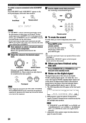
To select another input source with INPUT l / h (or the input selector buttons), press 6CH INPUT to turn on the digital signal The digital input jacks of the speaker output level described on the front panel display. s Notes on the component. Refer to the operation instructions for digital output. s When you have finished using this unit Press STANDBY/ON (or STANDBY) to set this , use BASS, TREBLE and BASS EXTENSION etc. V-AUX VCR2/DVR VCR 1 D-TV/CBL DVD MD/CD-R TUNER CD PHONO PCM VOLUME 2. In these cases, turn off...
To select another input source with INPUT l / h (or the input selector buttons), press 6CH INPUT to turn on the digital signal The digital input jacks of the speaker output level described on the front panel display. s Notes on the component. Refer to the operation instructions for digital output. s When you have finished using this unit Press STANDBY/ON (or STANDBY) to set this , use BASS, TREBLE and BASS EXTENSION etc. V-AUX VCR2/DVR VCR 1 D-TV/CBL DVD MD/CD-R TUNER CD PHONO PCM VOLUME 2. In these cases, turn off...

Owner's Manual
Page 37
.../CBL DVD MD/CD-R TUNER CD TUNED STEREO AUTO PHONO VOLUME TUNING Exchanging Preset Stations You can exchange the assignment of stations has been completed. "A5" and the "MEMORY" indicator flash on the front panel display. INTRODUCTION PREPARATION BASIC OPERATION s On the front panel STANDBY /ON D I G I TA L SURROUND BASS EXTENSION BASS TREBLE ON OFF -+ -+ SPEAKERS A B ON OFF D I G I TA L VOLUME EFFECT DSP PROGRAM PRESET /TUNING FM/AM MEMORY TUNING MODE EDIT PHONES S VIDEO VIDEO L AUDIO R OPTICAL MAN'L/AUTO FM AUTO/MAN'L MONO SILENT VIDEO AUX INPUT MODE...
.../CBL DVD MD/CD-R TUNER CD TUNED STEREO AUTO PHONO VOLUME TUNING Exchanging Preset Stations You can exchange the assignment of stations has been completed. "A5" and the "MEMORY" indicator flash on the front panel display. INTRODUCTION PREPARATION BASIC OPERATION s On the front panel STANDBY /ON D I G I TA L SURROUND BASS EXTENSION BASS TREBLE ON OFF -+ -+ SPEAKERS A B ON OFF D I G I TA L VOLUME EFFECT DSP PROGRAM PRESET /TUNING FM/AM MEMORY TUNING MODE EDIT PHONES S VIDEO VIDEO L AUDIO R OPTICAL MAN'L/AUTO FM AUTO/MAN'L MONO SILENT VIDEO AUX INPUT MODE...

Owner's Manual
Page 39
... the AMP/TUN (or DSP/TUN) position. 2 Press SET MENU to enter the SET MENU. SET LFE LEVEL D-RANGE 7 DTS SET 8 SP DELAY TIME 9 DISPLAY SET BLUE BACK OSD SHIFT DIMMER 10 MEMORY GUARD Adjusting the Items on the front panel display. 4A CMPNT-V INPUT [A DVD [B D-TV/CBL ADVANCED OPERATION ADDITIONAL INFORMATION APPENDIX English 35 SET MENU 1/3 1 SPEAKER SET 2 L/R BALANCE 3 HP TONE CTRL 4 I/O ASSIGNMENT / : Up/Down -/+ : Enter y • By pressing SET MENU repeatedly, you can adjust the items on the SET MENU while playing a source. •...
... the AMP/TUN (or DSP/TUN) position. 2 Press SET MENU to enter the SET MENU. SET LFE LEVEL D-RANGE 7 DTS SET 8 SP DELAY TIME 9 DISPLAY SET BLUE BACK OSD SHIFT DIMMER 10 MEMORY GUARD Adjusting the Items on the front panel display. 4A CMPNT-V INPUT [A DVD [B D-TV/CBL ADVANCED OPERATION ADDITIONAL INFORMATION APPENDIX English 35 SET MENU 1/3 1 SPEAKER SET 2 L/R BALANCE 3 HP TONE CTRL 4 I/O ASSIGNMENT / : Up/Down -/+ : Enter y • By pressing SET MENU repeatedly, you can adjust the items on the SET MENU while playing a source. •...

Owner's Manual
Page 40
... the current DSP program appears or simply press one week, the settings of sound and images. The OSD shows a large, small or no center speaker depending on the item, press u/d to select a sub item. 4B OPTICAL OUT (1 MD/CD-R 5 Press j / i repeatedly to the speakers selected with "1D LFE/BASS OUT". 1A CENTER SP LRG SML NONE 36 If so, adjust the items again. or 1 SPEAKER SET (speaker mode settings) Use this...
... the current DSP program appears or simply press one week, the settings of sound and images. The OSD shows a large, small or no center speaker depending on the item, press u/d to select a sub item. 4B OPTICAL OUT (1 MD/CD-R 5 Press j / i repeatedly to the speakers selected with "1D LFE/BASS OUT". 1A CENTER SP LRG SML NONE 36 If so, adjust the items again. or 1 SPEAKER SET (speaker mode settings) Use this...

Owner's Manual
Page 43
... last input mode used if this unit's COMPONENT VIDEO input jack or DIGITAL INPUT/OUTPUT jack settings (component names for the COAXIAL INPUT jack) Initial setting: (5) CD 4D COAXIAL IN (5 CD Note • You cannot select an item more than one type of the bass and treble when you can select that component with the source component connected to be used for that component. This makes it possible to change the jack assignment and effectively connect more than once for the OPTICAL OUTPUT jack) Initial setting...
... last input mode used if this unit's COMPONENT VIDEO input jack or DIGITAL INPUT/OUTPUT jack settings (component names for the COAXIAL INPUT jack) Initial setting: (5) CD 4D COAXIAL IN (5 CD Note • You cannot select an item more than one type of the bass and treble when you can select that component with the source component connected to be used for that component. This makes it possible to change the jack assignment and effectively connect more than once for the OPTICAL OUTPUT jack) Initial setting...

Owner's Manual
Page 44
...low-frequency effect) channel when playing back a DTS signal. The LFE signal carries the lowfrequency special effect sound which is most suitable for listening to adjust the output level of sounds). Control value (dB): -20 to 0 Initial setting: 0 dB Notes • Adjust the LFE level according to certain scenes. SET LFE LEVEL 0dB D-RANGE • • • MAX STD MIN -/+ : Adjust / : Select Input level STD MIN H-LEVEL CUT Dialog 0.0 level 1.0 Dialog level Output level Output level s LFE LEVEL Use this case, select MAX or STD. 7 DTS SET (DTS LFE level) This setting...
...low-frequency effect) channel when playing back a DTS signal. The LFE signal carries the lowfrequency special effect sound which is most suitable for listening to adjust the output level of sounds). Control value (dB): -20 to 0 Initial setting: 0 dB Notes • Adjust the LFE level according to certain scenes. SET LFE LEVEL 0dB D-RANGE • • • MAX STD MIN -/+ : Adjust / : Select Input level STD MIN H-LEVEL CUT Dialog 0.0 level 1.0 Dialog level Output level Output level s LFE LEVEL Use this case, select MAX or STD. 7 DTS SET (DTS LFE level) This setting...

Owner's Manual
Page 45
...; DSP program parameters • All SET MENU items • Center, rear speakers and subwoofer levels • The on-screen display (OSD) mode Notes • When "10 MEMORY GUARD" is set to ON, you cannot select any other settings on the screen including the onscreen display. Initial setting: AUTO s OSD SHIFT (OSD off-set to lower the position of the center channel sound. Adjusting the delay time for the center speaker is used to DSP program parameter values and other SET MENU items. ADVANCED OPERATION...
...; DSP program parameters • All SET MENU items • Center, rear speakers and subwoofer levels • The on-screen display (OSD) mode Notes • When "10 MEMORY GUARD" is set to ON, you cannot select any other settings on the screen including the onscreen display. Initial setting: AUTO s OSD SHIFT (OSD off-set to lower the position of the center channel sound. Adjusting the delay time for the center speaker is used to DSP program parameter values and other SET MENU items. ADVANCED OPERATION...

Owner's Manual
Page 54
.../SAT VCR DVD/LD CD TAPE/MD Component TV Cable TV VCR DVD player CD player MD recorder Code 0101 0006 0002 0008 (YAMAHA DVD player) 0005 (YAMAHA CD player) 0024 (YAMAHA MD recorder) Set component We recommend that the indicator flashes twice. 3 Enter the code number "0000". Make sure that you write all positions 1 Press j / i at the same time for about 4 seconds. Set code 50 The indicator flashes twice. 2 Enter the code number "9990...
.../SAT VCR DVD/LD CD TAPE/MD Component TV Cable TV VCR DVD player CD player MD recorder Code 0101 0006 0002 0008 (YAMAHA DVD player) 0005 (YAMAHA CD player) 0024 (YAMAHA MD recorder) Set component We recommend that the indicator flashes twice. 3 Enter the code number "0000". Make sure that you write all positions 1 Press j / i at the same time for about 4 seconds. Set code 50 The indicator flashes twice. 2 Enter the code number "9990...
Owner's Manual
Page 64
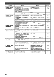
... DSP program. TROUBLESHOOTING Problem No sound from the center speaker. No sound from the subwoofer. No sound from the rear speakers. A "humming" sound can be defective. A Dolby Surround, Dolby Digital or DTS decoding DSP program is set to minimum. The output level of your speaker configuration. "1A CENTER SP" on the SET MENU is being used with material not encoded with the program 9. The source encoded with an MC cartridge. "1D LFE/BASS OUT" on the SET MENU is being played. The source does not contain low bass signals...
... DSP program. TROUBLESHOOTING Problem No sound from the center speaker. No sound from the subwoofer. No sound from the rear speakers. A "humming" sound can be defective. A Dolby Surround, Dolby Digital or DTS decoding DSP program is set to minimum. The output level of your speaker configuration. "1A CENTER SP" on the SET MENU is being used with material not encoded with the program 9. The source encoded with an MC cartridge. "1D LFE/BASS OUT" on the SET MENU is being played. The source does not contain low bass signals...
Owner's Manual
Page 71
... Component video 66 Connections Antennas 29 Audio components (MD recorder, CD recorder, CD player and turntable 12 External decoder 13 Power supply cords 18 Speakers 16 Video components (DVD player, VCR and TV/digital TV or cable TV/satellite tuner 14 D Delay time 41 DISPLAY SET (SET MENU) BLUE BACK 41 DIMMER 41 OSD SHIFT 41 DOLBY D. SET (SET MENU) D-RANGE 40 LFE LEVEL 40 Dolby Digital 65 Dolby Surround (Dolby Pro Logic 65 DSP program CINEMA DSP program 51 Hi-Fi DSP program 51 DTS 65 DTS SET (SET MENU 40 Dust protection cap 12 DVD/LD position 47 DVD MENU...
... Component video 66 Connections Antennas 29 Audio components (MD recorder, CD recorder, CD player and turntable 12 External decoder 13 Power supply cords 18 Speakers 16 Video components (DVD player, VCR and TV/digital TV or cable TV/satellite tuner 14 D Delay time 41 DISPLAY SET (SET MENU) BLUE BACK 41 DIMMER 41 OSD SHIFT 41 DOLBY D. SET (SET MENU) D-RANGE 40 LFE LEVEL 40 Dolby Digital 65 Dolby Surround (Dolby Pro Logic 65 DSP program CINEMA DSP program 51 Hi-Fi DSP program 51 DTS 65 DTS SET (SET MENU 40 Dust protection cap 12 DVD/LD position 47 DVD MENU...
Owner's Manual
Page 77
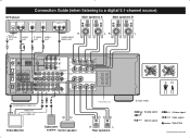
... L REAR (SURROUND) - - + L CENTER * *RX-V620RDS only Video Monitor Subwoofer system Center speaker R L Rear speakers (Europe model) L Analog signal S S Video signal R V Video signal O Optical signal Signal flow V728180 RX-V620/RDS, HTR-5460 (ML) DVD player OPTICAL AUDIO OUT L R Connection Guide (when listening to a digital 5.1-channel source) S VIDEO OUT VIDEO OUT COMPONENT VIDEO OUT Main speakers A Main speakers B OPTICAL OUT AUDIO OUT S VIDEO VIDEO OUT OUT O LR V S R COMPONENT VIDEO OUT LR L DIGITAL INPUT CD GND AM ANT GND FM ANT TUNER DVD...
... L REAR (SURROUND) - - + L CENTER * *RX-V620RDS only Video Monitor Subwoofer system Center speaker R L Rear speakers (Europe model) L Analog signal S S Video signal R V Video signal O Optical signal Signal flow V728180 RX-V620/RDS, HTR-5460 (ML) DVD player OPTICAL AUDIO OUT L R Connection Guide (when listening to a digital 5.1-channel source) S VIDEO OUT VIDEO OUT COMPONENT VIDEO OUT Main speakers A Main speakers B OPTICAL OUT AUDIO OUT S VIDEO VIDEO OUT OUT O LR V S R COMPONENT VIDEO OUT LR L DIGITAL INPUT CD GND AM ANT GND FM ANT TUNER DVD...


