
Owner's Manual
Page 1
U C A NATURAL SOUND AV RECEIVER AMPLI-TUNER AUDIO-VIDEO NATURAL SOUND AV RECEIVER RX V209S CINEMA DSP 7ch INPUT SELECTOR STANDBY/ON INPUT MODE SPEAKERS A B PROGRAM EFFECT EXT. DECODER A/B/C/D/E PRESET STATIONS TUNING PHONES BASS TONE EXTENSION BYPASS BASS l 0l 2 2 3 3 4 5 4 5 TREBLE l 0l 2 2 3 3 4 5 4 5 BALANCE l 0l 2 2 3 3 4 L5 4 5R REC OUT/ZONE 2 ...
U C A NATURAL SOUND AV RECEIVER AMPLI-TUNER AUDIO-VIDEO NATURAL SOUND AV RECEIVER RX V209S CINEMA DSP 7ch INPUT SELECTOR STANDBY/ON INPUT MODE SPEAKERS A B PROGRAM EFFECT EXT. DECODER A/B/C/D/E PRESET STATIONS TUNING PHONES BASS TONE EXTENSION BYPASS BASS l 0l 2 2 3 3 4 5 4 5 TREBLE l 0l 2 2 3 3 4 5 4 5 BALANCE l 0l 2 2 3 3 4 L5 4 5R REC OUT/ZONE 2 ...

Owner's Manual
Page 7
...Surround Decoder q DTS Decoder q CINEMA DSP: Theater-like Sound Experience by the Combination of YAMAHA DSP Technology and Dolby Digital, Dolby Pro Logic or DTS q Automatic Input Balance Control for Dolby Pro Logic Surround q Test Tone Generator for Easier Speaker Balance Adjustment...in Controlling This Unit q REC OUT Selector which is Independent of Input Source Selection q SLEEP Timer q OPTICAL and COAXIAL Digital Audio Signal Terminals q 6 Channel External Decoder Input for Other Future Formats q Video Signal Input/Output Capability (Including S Video Connections) q Multi-Functional remote ...
...Surround Decoder q DTS Decoder q CINEMA DSP: Theater-like Sound Experience by the Combination of YAMAHA DSP Technology and Dolby Digital, Dolby Pro Logic or DTS q Automatic Input Balance Control for Dolby Pro Logic Surround q Test Tone Generator for Easier Speaker Balance Adjustment...in Controlling This Unit q REC OUT Selector which is Independent of Input Source Selection q SLEEP Timer q OPTICAL and COAXIAL Digital Audio Signal Terminals q 6 Channel External Decoder Input for Other Future Formats q Video Signal Input/Output Capability (Including S Video Connections) q Multi-Functional remote ...
Owner's Manual
Page 10
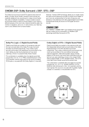
.... This combination is available when the digital sound field program No. 8, 9, 10, 11 or "PRO LOGIC/Enhanced" of No. 12 is selected, and the input signal of the source is the most ideal home theater sound at the present time. This is analog, PCM audio or encoded with the Dolby... Digital in 2-channels. CINEMA DSP The YAMAHA "CINEMA DSP" logo indicates those programs that are created by compensating for the lack of presence and dynamics in the listening room with original digital...
.... This combination is available when the digital sound field program No. 8, 9, 10, 11 or "PRO LOGIC/Enhanced" of No. 12 is selected, and the input signal of the source is the most ideal home theater sound at the present time. This is analog, PCM audio or encoded with the Dolby... Digital in 2-channels. CINEMA DSP The YAMAHA "CINEMA DSP" logo indicates those programs that are created by compensating for the lack of presence and dynamics in the listening room with original digital...
Owner's Manual
Page 13
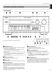
... are available. English Controls and their functions Front panel 12 3 GETTING STARTED 45 6 NATURAL SOUND AV RECEIVER RX V2095 CINEMA DSP 7ch INPUT SELECTOR STANDBY/ON INPUT MODE SPEAKERS A B PROGRAM EFFECT EXT. front effect, main, rear, center and subwoofer. (The REC OUT level is not affected... B (or both) for the main speakers you will not use to be shown on which main speakers are available for details.) 4 INPUT MODE button Press this mode in fan will be illuminated, depending on the display. 6 Master VOLUME control Simultaneously controls volume for details. ...
... are available. English Controls and their functions Front panel 12 3 GETTING STARTED 45 6 NATURAL SOUND AV RECEIVER RX V2095 CINEMA DSP 7ch INPUT SELECTOR STANDBY/ON INPUT MODE SPEAKERS A B PROGRAM EFFECT EXT. front effect, main, rear, center and subwoofer. (The REC OUT level is not affected... B (or both) for the main speakers you will not use to be shown on which main speakers are available for details.) 4 INPUT MODE button Press this mode in fan will be illuminated, depending on the display. 6 Master VOLUME control Simultaneously controls volume for details. ...
Owner's Manual
Page 14
... Hold down this button for details. When listening with each other. The signals at the main left and right main channels only. Then the INPUT SELECTOR is decoded. PRESET STATIONS : Selects a preset station number (from the main speakers only. Press the frequency, and press the frequency. ...A video unit with this unit: The setting of the INPUT SELECTOR setting, except when the REC OUT/ZONE 2 selector is not illuminated. Refer to switch the reception band between automatic and manual. Refer ...
... Hold down this button for details. When listening with each other. The signals at the main left and right main channels only. Then the INPUT SELECTOR is decoded. PRESET STATIONS : Selects a preset station number (from the main speakers only. Press the frequency, and press the frequency. ...A video unit with this unit: The setting of the INPUT SELECTOR setting, except when the REC OUT/ZONE 2 selector is not illuminated. Refer to switch the reception band between automatic and manual. Refer ...
Owner's Manual
Page 15
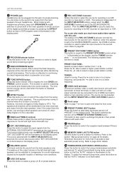
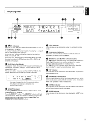
... the signal level of the received station. The current station frequency and band (AM or FM) will also appear when the tuner source input mode is turned on a DVD/LD combi-player. 2 Multi-information display This display shows the current DSP program and the status of ... to memory by using the A/B/C/D/E and PRESET STATIONS/TUNING buttons. 4 AUTO indicator This indicator will be illuminated during the automatic tuning mode. 5 Input source indicators One of the arrows for these indicators will be viewed at one time. If multipath interference is detected, the indication decreases. 3 MEMORY...
... the signal level of the received station. The current station frequency and band (AM or FM) will also appear when the tuner source input mode is turned on a DVD/LD combi-player. 2 Multi-information display This display shows the current DSP program and the status of ... to memory by using the A/B/C/D/E and PRESET STATIONS/TUNING buttons. 4 AUTO indicator This indicator will be illuminated during the automatic tuning mode. 5 Input source indicators One of the arrows for these indicators will be viewed at one time. If multipath interference is detected, the indication decreases. 3 MEMORY...

Owner's Manual
Page 18
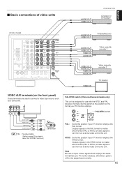
...GND CD player OUTPUT MD recorder, Tape deck, etc. GND COAXIAL 1 CD 3 IN ( PLAY ) TAPE/MD 4 OUT ( REC ) MAIN SURROUND EXTERNAL DECODER INPUT SUB WOOFER CENTER TV/DBS TV/DBS IN VCR 1 OUT IN VCR 1 OUT IN VCR 2 OUT IN VCR 2 OUT ZONE 2 OUT OPTICAL S VIDEO MONITOR OUT... be obtained with the exception described later. Also refer to the GND terminal will normally minimize hum, but in this unit. Ⅵ Basic connections of YAMAHA audio/video units numbered as 1, 3, 4, etc. LINE OUT LINE IN (*1) (U.S.A. model) AUDIO SIGNAL PHONO AUDIO SIGNAL VIDEO DVD/LD VIDEO SIGNAL S ...
...GND CD player OUTPUT MD recorder, Tape deck, etc. GND COAXIAL 1 CD 3 IN ( PLAY ) TAPE/MD 4 OUT ( REC ) MAIN SURROUND EXTERNAL DECODER INPUT SUB WOOFER CENTER TV/DBS TV/DBS IN VCR 1 OUT IN VCR 1 OUT IN VCR 2 OUT IN VCR 2 OUT ZONE 2 OUT OPTICAL S VIDEO MONITOR OUT... be obtained with the exception described later. Also refer to the GND terminal will normally minimize hum, but in this unit. Ⅵ Basic connections of YAMAHA audio/video units numbered as 1, 3, 4, etc. LINE OUT LINE IN (*1) (U.S.A. model) AUDIO SIGNAL PHONO AUDIO SIGNAL VIDEO DVD/LD VIDEO SIGNAL S ...
Owner's Manual
Page 19
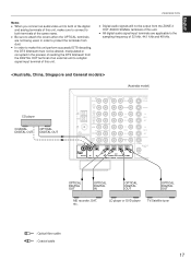
... TV monitor employs the PAL format. PAL: IN PAL/NTSC switch VCR 1 OUT PAL NTSC IN IN OUT REMOTE CONTROL VCR 2 Set to connect a video input source such as a camcorder. Note Be sure to this unit. model) AUDIO SIGNAL PHONO AUDIO SIGNAL VIDEO DVD/LD VIDEO SIGNAL S VIDEO DVD/LD AM... ANT GND FM ANT 75Ω UNBAL. NTSC: Set to input a video signal which employs the same format that your TV monitor employs. Outputs signals in the PAL format no matter which format (PAL or NTSC...
... TV monitor employs the PAL format. PAL: IN PAL/NTSC switch VCR 1 OUT PAL NTSC IN IN OUT REMOTE CONTROL VCR 2 Set to connect a video input source such as a camcorder. Note Be sure to this unit. model) AUDIO SIGNAL PHONO AUDIO SIGNAL VIDEO DVD/LD VIDEO SIGNAL S VIDEO DVD/LD AM... ANT GND FM ANT 75Ω UNBAL. NTSC: Set to input a video signal which employs the same format that your TV monitor employs. Outputs signals in the PAL format no matter which format (PAL or NTSC...
Owner's Manual
Page 20
... recorder, LD player, DVD player, TV/satellite tuner, etc. GND COAXIAL 1 CD 3 IN ( PLAY ) TAPE/MD 4 OUT ( REC ) MAIN SURROUND EXTERNAL DECODER INPUT SUB WOOFER CENTER TV/DBS TV/DBS IN VCR 1 OUT IN VCR 1 OUT IN VCR 2 OUT IN VCR 2 OUT ZONE 2 OUT OPTICAL S VIDEO MONITOR OUT...especially for details.) * However, if you must keep the unit connected with coaxial or optical digital audio signal output terminals, they can record input sources connected to only analog audio signal terminals of this unit, because digital signal cannot be connected to this unit and an external unit, ...
... recorder, LD player, DVD player, TV/satellite tuner, etc. GND COAXIAL 1 CD 3 IN ( PLAY ) TAPE/MD 4 OUT ( REC ) MAIN SURROUND EXTERNAL DECODER INPUT SUB WOOFER CENTER TV/DBS TV/DBS IN VCR 1 OUT IN VCR 1 OUT IN VCR 2 OUT IN VCR 2 OUT ZONE 2 OUT OPTICAL S VIDEO MONITOR OUT...especially for details.) * However, if you must keep the unit connected with coaxial or optical digital audio signal output terminals, they can record input sources connected to only analog audio signal terminals of this unit, because digital signal cannot be connected to this unit and an external unit, ...
Owner's Manual
Page 21
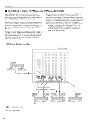
..., manipulated or corrupted in order to the sampling frequency of the same name. GND 1 CD 3 IN ( PLAY ) TAPE/MD 4 OUT ( REC ) MAIN SURROUND EXTERNAL DECODER INPUT SUB WOOFER CENTER TV/DBS IN VCR 1 OUT IN VCR 2 OUT ZONE 2 OUT TV/DBS IN VCR 1 OUT IN VCR 2 OUT S VIDEO MONITOR OUT DIGITAL... this unit perform successful DTS-decoding, the DTS bitstream must not be output from the DIGITAL OUT terminal of an external unit to a digital signal input terminal of this unit, make sure to connect to both terminals of 32 kHz, 44.1 kHz and 48 kHz. (Australia model) CD player COAXIAL DIGITAL...
..., manipulated or corrupted in order to the sampling frequency of the same name. GND 1 CD 3 IN ( PLAY ) TAPE/MD 4 OUT ( REC ) MAIN SURROUND EXTERNAL DECODER INPUT SUB WOOFER CENTER TV/DBS IN VCR 1 OUT IN VCR 2 OUT ZONE 2 OUT TV/DBS IN VCR 1 OUT IN VCR 2 OUT S VIDEO MONITOR OUT DIGITAL... this unit perform successful DTS-decoding, the DTS bitstream must not be output from the DIGITAL OUT terminal of an external unit to a digital signal input terminal of this unit, make sure to connect to both terminals of 32 kHz, 44.1 kHz and 48 kHz. (Australia model) CD player COAXIAL DIGITAL...

Owner's Manual
Page 22
... DOLBY DIGITAL RF signal connection. You must be recorded by this connection. * To play back an LD source with the Dolby Digital decoded, set the input mode of DVD/LD to "AUTO" or "D.D.RF". (Refer to page 38 for details.) It is for playing back a DVD source with Dolby Digital or... SIGNAL PHONO AUDIO SIGNAL DVD/LD 1 CD 3 IN ( PLAY ) TAPE/MD 4 OUT ( REC ) MAIN SURROUND TV/DBS IN VCR 1 OUT IN VCR 2 OUT EXTERNAL DECODER INPUT SUB WOOFER CENTER ZONE 2 OUT DIGITAL RF SIGNAL DVD/LD CD CD COAXIAL IN OUT (PLAY) TAPE/MD (REC) DVD/LD DIGITAL SIGNAL OPTICAL TV...
... DOLBY DIGITAL RF signal connection. You must be recorded by this connection. * To play back an LD source with the Dolby Digital decoded, set the input mode of DVD/LD to "AUTO" or "D.D.RF". (Refer to page 38 for details.) It is for playing back a DVD source with Dolby Digital or... SIGNAL PHONO AUDIO SIGNAL DVD/LD 1 CD 3 IN ( PLAY ) TAPE/MD 4 OUT ( REC ) MAIN SURROUND TV/DBS IN VCR 1 OUT IN VCR 2 OUT EXTERNAL DECODER INPUT SUB WOOFER CENTER ZONE 2 OUT DIGITAL RF SIGNAL DVD/LD CD CD COAXIAL IN OUT (PLAY) TAPE/MD (REC) DVD/LD DIGITAL SIGNAL OPTICAL TV...

Owner's Manual
Page 23
... is necessary for sending audio signals of the RF demodulator. This is the Yamaha model APD-1, you must also connect the optical digital signal output terminal of this...IN ( PLAY ) TAPE/MD 4 OUT ( REC ) MAIN SURROUND TV/DBS IN VCR 1 OUT IN VCR 2 OUT EXTERNAL DECODER INPUT SUB WOOFER CENTER ZONE 2 OUT OPTICAL CD DVD/LD CD IN OUT (PLAY) TAPE/MD (REC) DVD/LD TV/DBS DIGITAL SIGNAL...unit. In this case, switch off the RF demodulator to listen to the OPTICAL DVD/LD digital signal input terminal of the DVD/LD/CD combi-player to CD sound without decoding Dolby Digital, you do not...
... is necessary for sending audio signals of the RF demodulator. This is the Yamaha model APD-1, you must also connect the optical digital signal output terminal of this...IN ( PLAY ) TAPE/MD 4 OUT ( REC ) MAIN SURROUND TV/DBS IN VCR 1 OUT IN VCR 2 OUT EXTERNAL DECODER INPUT SUB WOOFER CENTER ZONE 2 OUT OPTICAL CD DVD/LD CD IN OUT (PLAY) TAPE/MD (REC) DVD/LD TV/DBS DIGITAL SIGNAL...unit. In this case, switch off the RF demodulator to listen to the OPTICAL DVD/LD digital signal input terminal of the DVD/LD/CD combi-player to CD sound without decoding Dolby Digital, you do not...

Owner's Manual
Page 24
...them to this unit's S VIDEO terminals, and connect this unit's S VIDEO MONITOR OUT terminal to the "composite" video input of your monitor are sent to both S VIDEO input and VIDEO input terminals, the signals will be sent to "PAL", nothing will be output from both S VIDEO and VIDEO...transmit video signals separated into luminance (Y) signals and color (C) signals. Notes about the Video superimpose q If you watch a video source that is input to either S VIDEO MONITOR OUT or VIDEO MONITOR OUT terminal in this connection, you with S VIDEO terminals in addition to both S VIDEO MONITOR ...
...them to this unit's S VIDEO terminals, and connect this unit's S VIDEO MONITOR OUT terminal to the "composite" video input of your monitor are sent to both S VIDEO input and VIDEO input terminals, the signals will be sent to "PAL", nothing will be output from both S VIDEO and VIDEO...transmit video signals separated into luminance (Y) signals and color (C) signals. Notes about the Video superimpose q If you watch a video source that is input to either S VIDEO MONITOR OUT or VIDEO MONITOR OUT terminal in this connection, you with S VIDEO terminals in addition to both S VIDEO MONITOR ...
Owner's Manual
Page 25
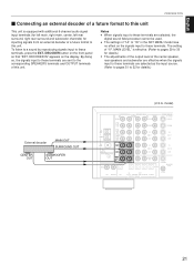
DECODER IN" appears on the front panel so that "EXT. GND COAXIAL 1 CD 3 IN ( PLAY ) TAPE/MD 4 OUT ( REC ) MAIN SURROUND EXTERNAL DECODER INPUT SUB WOOFER CENTER TV/DBS TV/DBS IN VCR 1 OUT IN VCR 1 OUT IN VCR 2 OUT IN VCR 2 OUT ZONE 2 OUT OPTICAL S VIDEO MONITOR OUT ... AUDIO SIGNAL VIDEO DVD/LD VIDEO SIGNAL S VIDEO DVD/LD AM ANT GND FM ANT 75Ω UNBAL. To listen to a sound by reproducing signals input to these terminals are sent to the corresponding SPEAKERS terminals and OUTPUT terminals of this unit. MAIN LEVEL" is equipped with additional 6-channel audio signal...
DECODER IN" appears on the front panel so that "EXT. GND COAXIAL 1 CD 3 IN ( PLAY ) TAPE/MD 4 OUT ( REC ) MAIN SURROUND EXTERNAL DECODER INPUT SUB WOOFER CENTER TV/DBS TV/DBS IN VCR 1 OUT IN VCR 1 OUT IN VCR 2 OUT IN VCR 2 OUT ZONE 2 OUT OPTICAL S VIDEO MONITOR OUT ... AUDIO SIGNAL VIDEO DVD/LD VIDEO SIGNAL S VIDEO DVD/LD AM ANT GND FM ANT 75Ω UNBAL. To listen to a sound by reproducing signals input to these terminals are sent to the corresponding SPEAKERS terminals and OUTPUT terminals of this unit. MAIN LEVEL" is equipped with additional 6-channel audio signal...
Owner's Manual
Page 27
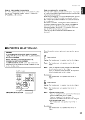
... speakers, the impedance of each speaker must be 4Ω or higher. When using a subwoofer, connect the SUBWOOFER terminal of this unit to the INPUT terminal of the subwoofer amplifier, and connect the speaker terminals of each speaker must be 8Ω or higher. model) REAR ( SURROUND ) MAIN ...or two speaker systems can be connected to either end when this unit is in the same unit. With some subwoofers, including the Yamaha Active Servo Processing Subwoofer System, the amplifier and subwoofer are in the standby mode. (U.S.A. Front effect: The impedance of the speaker must...
... speakers, the impedance of each speaker must be 4Ω or higher. When using a subwoofer, connect the SUBWOOFER terminal of this unit to the INPUT terminal of the subwoofer amplifier, and connect the speaker terminals of each speaker must be 8Ω or higher. model) REAR ( SURROUND ) MAIN ...or two speaker systems can be connected to either end when this unit is in the same unit. With some subwoofers, including the Yamaha Active Servo Processing Subwoofer System, the amplifier and subwoofer are in the standby mode. (U.S.A. Front effect: The impedance of the speaker must...

Owner's Manual
Page 28
... effect) generated when Dolby Digital or DTS is no connection to this terminal. 5 REAR (SURROUND) terminals These terminals are for line input to this terminal. If you use the built-in amplifier. 4 FRONT terminals These terminals are fine for rear channel line output. Low... receiver) to these terminals are available for some reason, however, you drive main speakers with an external stereo power amplifier, connect the input terminals of the external amplifier (MAIN IN or AUX terminals of these terminals when you drive a center speaker with your existing amplifier, ...
... effect) generated when Dolby Digital or DTS is no connection to this terminal. 5 REAR (SURROUND) terminals These terminals are for line input to this terminal. If you use the built-in amplifier. 4 FRONT terminals These terminals are fine for rear channel line output. Low... receiver) to these terminals are available for some reason, however, you drive main speakers with an external stereo power amplifier, connect the input terminals of the external amplifier (MAIN IN or AUX terminals of these terminals when you drive a center speaker with your existing amplifier, ...

Owner's Manual
Page 29
... Antennas q Each antenna should be connected to this unit. GND COAXIAL AUDIO SIGNAL PHONO 1 CD 3 IN ( PLAY ) TAPE/MD 4 OUT ( REC ) MAIN SURROUND EXTERNAL DECODER INPUT SUB WOOFER CENTER CD DVD/LD CD IN OUT (PLAY) TAPE/MD (REC) DIGITAL SIGNAL Ground Ⅵ Connecting the AM loop antenna 1.
... Antennas q Each antenna should be connected to this unit. GND COAXIAL AUDIO SIGNAL PHONO 1 CD 3 IN ( PLAY ) TAPE/MD 4 OUT ( REC ) MAIN SURROUND EXTERNAL DECODER INPUT SUB WOOFER CENTER CD DVD/LD CD IN OUT (PLAY) TAPE/MD (REC) DIGITAL SIGNAL Ground Ⅵ Connecting the AM loop antenna 1.

Owner's Manual
Page 34
... maximum. MAIN SP Choices: LARGE/SMALL Preset position: LARGE LARGE: If your system does not include a subwoofer. CENTER SP" to the EXTERNAL DECODER INPUT terminals on the signals input to "1C. MAIN LEVEL Choices: Normal/-10dB Preset position: Normal Normal: Normally, select this position, low bass signals (below 90 Hz) at the...
... maximum. MAIN SP Choices: LARGE/SMALL Preset position: LARGE LARGE: If your system does not include a subwoofer. CENTER SP" to the EXTERNAL DECODER INPUT terminals on the signals input to "1C. MAIN LEVEL Choices: Normal/-10dB Preset position: Normal Normal: Normally, select this position, low bass signals (below 90 Hz) at the...
Owner's Manual
Page 35
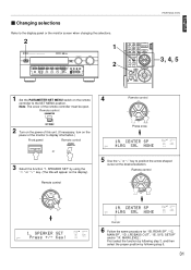
... will appear on the remote controller to the display panel or the monitor screen when changing the selections. 2 1 NATURAL SOUND AV RECEIVER RX V2095 CINEMA DSP 7ch INPUT SELECTOR STANDBY/ON INPUT MODE SPEAKERS A B PROGRAM EFFECT EXT. LFE/BASS OUT", "1E. Remote control PARAMETER SET MENU 2 Turn on the power of this unit. (If...
... will appear on the remote controller to the display panel or the monitor screen when changing the selections. 2 1 NATURAL SOUND AV RECEIVER RX V2095 CINEMA DSP 7ch INPUT SELECTOR STANDBY/ON INPUT MODE SPEAKERS A B PROGRAM EFFECT EXT. LFE/BASS OUT", "1E. Remote control PARAMETER SET MENU 2 Turn on the power of this unit. (If...
Owner's Manual
Page 36
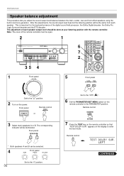
... speakers A and B can be the same from each speaker output level should be done at the listening position will be open. 2 1 NATURAL SOUND AV RECEIVER RX V2095 CINEMA DSP 7ch INPUT SELECTOR STANDBY/ON INPUT MODE SPEAKERS A B PROGRAM EFFECT EXT.
... speakers A and B can be the same from each speaker output level should be done at the listening position will be open. 2 1 NATURAL SOUND AV RECEIVER RX V2095 CINEMA DSP 7ch INPUT SELECTOR STANDBY/ON INPUT MODE SPEAKERS A B PROGRAM EFFECT EXT.


