
MCXSP10 Manual
Page 5
... 22 Connecting a multi-format player or an external decoder 26 Connecting a YAMAHA iPod universal dock ........ 27 Using the VIDEO AUX jacks on the front panel .... 27 Connecting the FM and AM antennas 28 Connecting the power cable 29 Setting the speaker impedance 30 Turning on and off the power 31 AUTO SETUP...
... 22 Connecting a multi-format player or an external decoder 26 Connecting a YAMAHA iPod universal dock ........ 27 Using the VIDEO AUX jacks on the front panel .... 27 Connecting the FM and AM antennas 28 Connecting the power cable 29 Setting the speaker impedance 30 Turning on and off the power 31 AUTO SETUP...
MCXSP10 Manual
Page 6
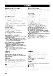
... (such as the YDS-10, sold separately), which supports iPod (Click and Wheel), iPod nano, and iPod mini Other features ◆ YPAO (YAMAHA Parametric Room Acoustic Optimizer) for automatic speaker setup ◆ 192-kHz/24-bit D/A converter ◆ OSD (on HDMI version 1.2a ◆ Analog video to HDMI digital video up-conversion...
... (such as the YDS-10, sold separately), which supports iPod (Click and Wheel), iPod nano, and iPod mini Other features ◆ YPAO (YAMAHA Parametric Room Acoustic Optimizer) for automatic speaker setup ◆ 192-kHz/24-bit D/A converter ◆ OSD (on HDMI version 1.2a ◆ Analog video to HDMI digital video up-conversion...
MCXSP10 Manual
Page 7
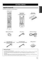
... DISPLAY EFFECT CLASSICAL LIVE/CLUB ENTERTAIN MOVIE 1 2 3 4 STEREO SUR. ID1 ID2 NUMBER ZONE 2 ZONE 3 Speaker terminal wrench Power cable GETTING STARTED Batteries (6) (AAA, R03, UM-4) Optimizer microphone Indoor FM antenna (U.S.A., Canada, China...control, the button name on the remote control. In case of improvements, etc. Remote control POWER TV POWER AV STANDBY POWER XM AUDIO SEL SLEEP PHONO TUNER CD MULTI CH IN V-AUX/DOCK CBL/SAT MD/TAPE CD... subject to production. INTRODUCTION GETTING STARTED Supplied accessories Check that you received all of the following parts.
... DISPLAY EFFECT CLASSICAL LIVE/CLUB ENTERTAIN MOVIE 1 2 3 4 STEREO SUR. ID1 ID2 NUMBER ZONE 2 ZONE 3 Speaker terminal wrench Power cable GETTING STARTED Batteries (6) (AAA, R03, UM-4) Optimizer microphone Indoor FM antenna (U.S.A., Canada, China...control, the button name on the remote control. In case of improvements, etc. Remote control POWER TV POWER AV STANDBY POWER XM AUDIO SEL SLEEP PHONO TUNER CD MULTI CH IN V-AUX/DOCK CBL/SAT MD/TAPE CD... subject to production. INTRODUCTION GETTING STARTED Supplied accessories Check that you received all of the following parts.
MCXSP10 Manual
Page 8
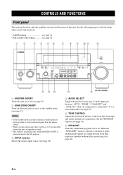
...input jacks (see page 40). 5 TONE CONTROL Adjusts the bass/treble balance of the front left, front right and center channels in order to receive infrared signals from the remote control. • When you turn on this unit, there will be a 4 to 5-second delay before this ...jack between "AUTO", "HDMI", "COAX/OPT" and "ANALOG" when one component is selected, 2-channel or multichannel input signals are output directly from their respective speakers without effect processing (see page 62 12 3 4 56 7 8 9 0A B MAIN ZONE ON/OFF ON OFF MASTER INPUT AUDIO SELECT TONE CONTROL A/B/C/D/E CATEGORY...
...input jacks (see page 40). 5 TONE CONTROL Adjusts the bass/treble balance of the front left, front right and center channels in order to receive infrared signals from the remote control. • When you turn on this unit, there will be a 4 to 5-second delay before this ...jack between "AUTO", "HDMI", "COAX/OPT" and "ANALOG" when one component is selected, 2-channel or multichannel input signals are output directly from their respective speakers without effect processing (see page 62 12 3 4 56 7 8 9 0A B MAIN ZONE ON/OFF ON OFF MASTER INPUT AUDIO SELECT TONE CONTROL A/B/C/D/E CATEGORY...

MCXSP10 Manual
Page 10
...TRANSMIT indicator Flashes while the remote control is sending infrared signals. 3 Input selector buttons Select the input source you can control. 5 LEVEL Selects the speaker channel to be adjusted and sets the output level (see page 51). 6 Cursor buttons k / n / l / h, ENTER Select and ...the previous menu level when adjusting the "SET MENU" parameters. 8 Sound field program selector buttons Select sound field programs (see page 103 1 2 3 POWER TV POWER AV STANDBY POWER XM AUDIO SEL SLEEP PHONO TUNER CD MULTI CH IN V-AUX/DOCK CBL/SAT MD/TAPE CD-R B C D E F DTV VCR 1 DVR/VCR ...
...TRANSMIT indicator Flashes while the remote control is sending infrared signals. 3 Input selector buttons Select the input source you can control. 5 LEVEL Selects the speaker channel to be adjusted and sets the output level (see page 51). 6 Cursor buttons k / n / l / h, ENTER Select and ...the previous menu level when adjusting the "SET MENU" parameters. 8 Sound field program selector buttons Select sound field programs (see page 103 1 2 3 POWER TV POWER AV STANDBY POWER XM AUDIO SEL SLEEP PHONO TUNER CD MULTI CH IN V-AUX/DOCK CBL/SAT MD/TAPE CD-R B C D E F DTV VCR 1 DVR/VCR ...

MCXSP10 Manual
Page 11
...", "HDMI", "COAX/OPT" and "ANALOG" when one set the remote control codes for DTV/CBL. U LEARN Programs remote control codes of functions from their respective speakers without effect processing (see page 106). R NIGHT Turns on or off the macro function (see page 107). B STANDBY Sets the main zone to be controlled...
...", "HDMI", "COAX/OPT" and "ANALOG" when one set the remote control codes for DTV/CBL. U LEARN Programs remote control codes of functions from their respective speakers without effect processing (see page 106). R NIGHT Turns on or off the macro function (see page 107). B STANDBY Sets the main zone to be controlled...

MCXSP10 Manual
Page 14
...EX MATRIX DISCRETE J F 96 K 24 G 7 8 9 TUNED STEREO L AUTO MEMORY M PS ZONE2 PTY N ZONE3 RT NIGHT CT O SLEEP EON P PTY HOLD 0 ........ Presence and surround back speaker indicators Light up according to the number of the XM indicator lights up only when "XM" is input to the U.S.A. For details, see page 41...input source is input at HDMI IN 1 or HDMI IN 2 jacks (see page 19). 2 DOCK indicator Lights up when you station your iPod in a YAMAHA iPod universal dock (such as the YDS-10, sold separately) connected to "ON" (see page 89) in the standby mode of this unit. (see...
...EX MATRIX DISCRETE J F 96 K 24 G 7 8 9 TUNED STEREO L AUTO MEMORY M PS ZONE2 PTY N ZONE3 RT NIGHT CT O SLEEP EON P PTY HOLD 0 ........ Presence and surround back speaker indicators Light up according to the number of the XM indicator lights up only when "XM" is input to the U.S.A. For details, see page 41...input source is input at HDMI IN 1 or HDMI IN 2 jacks (see page 19). 2 DOCK indicator Lights up when you station your iPod in a YAMAHA iPod universal dock (such as the YDS-10, sold separately) connected to "ON" (see page 89) in the standby mode of this unit. (see...

MCXSP10 Manual
Page 15
...indicators (U.K. CINEMA DSP indicator Lights up when this unit function. TUNED indicator Lights up when you run "AUTO SETUP" and when the speaker settings set in the PTY SEEK mode. 11 En HiFi DSP indicator Lights up when Virtual CINEMA DSP is reproducing PCM (Pulse Code ... up when you select a HiFi DSP sound field program (see page 49). and Canada models only) Lights up when this unit is being received. INTRODUCTION 0 neural indicator (U.S.A. D DSD indicator Lights up when the Neural Surround decoder is producing DSD (Direct Stream Digital) digital audio signals....
...indicators (U.K. CINEMA DSP indicator Lights up when this unit function. TUNED indicator Lights up when you run "AUTO SETUP" and when the speaker settings set in the PTY SEEK mode. 11 En HiFi DSP indicator Lights up when Virtual CINEMA DSP is reproducing PCM (Pulse Code ... up when you select a HiFi DSP sound field program (see page 49). and Canada models only) Lights up when this unit is being received. INTRODUCTION 0 neural indicator (U.S.A. D DSD indicator Lights up when the Neural Surround decoder is producing DSD (Direct Stream Digital) digital audio signals....

MCXSP10 Manual
Page 16
...-232C terminal This is a control expansion terminal for connection information. 12 En E Speaker terminals See page 14 for factory use (see page 15). 7 VOLTAGE SELECTOR (...) OUT (REC) MD/ TAPE L R CENTER FRONT(6CH) SURROUND CENTER FRONT SURROUND SINGLE(SB) ZONE 2 ZONE 3 VIDEO R+ SP1 PRESENCE SPEAKERS +L + SURROUND BACK/ BI-AMP + CENTER SINGLE WRENCH HOLDER + CBL/ SAT IN 1 DVD OUT R DOCK IN(PLAY) AUDIO XM OUT...for connection information. 6 WRENCH HOLDER Use to hook the supplied speaker terminal wrench when not in use only. Consult your dealer for connection information.
...-232C terminal This is a control expansion terminal for connection information. 12 En E Speaker terminals See page 14 for factory use (see page 15). 7 VOLTAGE SELECTOR (...) OUT (REC) MD/ TAPE L R CENTER FRONT(6CH) SURROUND CENTER FRONT SURROUND SINGLE(SB) ZONE 2 ZONE 3 VIDEO R+ SP1 PRESENCE SPEAKERS +L + SURROUND BACK/ BI-AMP + CENTER SINGLE WRENCH HOLDER + CBL/ SAT IN 1 DVD OUT R DOCK IN(PLAY) AUDIO XM OUT...for connection information. 6 WRENCH HOLDER Use to hook the supplied speaker terminal wrench when not in use only. Consult your dealer for connection information.

MCXSP10 Manual
Page 17
.... Subwoofer (SW) The use of a subwoofer with a built-in order to -back transitions. Place these speakers at the front of the room to the monitor as possible, such as the YAMAHA Active Servo Processing Subwoofer System, is not so critical, because low bass sounds are used for effect and... surround sounds. Surround back left and right speakers (SL and SR) The surround speakers are not highly directional. Place these speakers at the same height...
.... Subwoofer (SW) The use of a subwoofer with a built-in order to -back transitions. Place these speakers at the front of the room to the monitor as possible, such as the YAMAHA Active Servo Processing Subwoofer System, is not so critical, because low bass sounds are used for effect and... surround sounds. Surround back left and right speakers (SL and SR) The surround speakers are not highly directional. Place these speakers at the same height...

MCXSP10 Manual
Page 18
... monitor. • If you are colored or shaped differently, perhaps with the monitor, place the speakers away from the speakers, and if the polarity of the speaker connections is actually a pair of insulated cables running side by side. This could damage this unit...connect the left channel (L), right channel (R), "+" (red) and "-" (black) properly. Subwoofer Surround back speakers Presence speakers Left Right Right Left Center speaker (U.S.A. CAUTION • Before connecting the speakers, make sure that this unit is turned off (see page 118). You can set to prioritize either ...
... monitor. • If you are colored or shaped differently, perhaps with the monitor, place the speakers away from the speakers, and if the polarity of the speaker connections is actually a pair of insulated cables running side by side. This could damage this unit...connect the left channel (L), right channel (R), "+" (red) and "-" (black) properly. Subwoofer Surround back speakers Presence speakers Left Right Right Left Center speaker (U.S.A. CAUTION • Before connecting the speakers, make sure that this unit is turned off (see page 118). You can set to prioritize either ...

MCXSP10 Manual
Page 19
... use a surround back speaker, connect the speaker to these terminals. CONNECTIONS ■ Connecting the speaker cable 1 Remove approximately 10 mm (0.4 in) of insulation from the end of the cable together to prevent short circuits. 10 mm (0.4 in amplifier (such as the YAMAHA Active Servo Processing Subwoofer ...System) to this jack. Speaker terminal wrench Red: positive (+) Black: negative (-) 3 Insert one bare wire into the hole on the side of...
... use a surround back speaker, connect the speaker to these terminals. CONNECTIONS ■ Connecting the speaker cable 1 Remove approximately 10 mm (0.4 in) of insulation from the end of the cable together to prevent short circuits. 10 mm (0.4 in amplifier (such as the YAMAHA Active Servo Processing Subwoofer ...System) to this jack. Speaker terminal wrench Red: positive (+) Black: negative (-) 3 Insert one bare wire into the hole on the side of...

MCXSP10 Manual
Page 20
...Europe, Asia and Korea models) The banana plug is a single-pole electrical connector widely used to terminate speaker cables. Banana plug ■ Connecting to the SP2 speaker terminals Connect Zone 2 or Zone 3 speakers to secure the wire. Open the tab and then insert one bare wire into the hole on the terminal...positive (+) Black: negative (-) 2 Insert one banana plug into the end of this unit when not in use the banana plug with the SP2 speaker terminals. Red: positive (+) Black: negative (-) 2 Insert the banana plug connector into the hole on the terminal. CONNECTIONS 5 Hook the...
...Europe, Asia and Korea models) The banana plug is a single-pole electrical connector widely used to terminate speaker cables. Banana plug ■ Connecting to the SP2 speaker terminals Connect Zone 2 or Zone 3 speakers to secure the wire. Open the tab and then insert one bare wire into the hole on the terminal...positive (+) Black: negative (-) 2 Insert one banana plug into the end of this unit when not in use the banana plug with the SP2 speaker terminals. Red: positive (+) Black: negative (-) 2 Insert the banana plug connector into the hole on the terminal. CONNECTIONS 5 Hook the...

MCXSP10 Manual
Page 21
... terminals. This unit allows you will note shorting bars or bridges, one speaker system. Check if your speakers as shown below. PREPARATION CONNECTIONS Using bi-amplification connections Some of the speakers have speaker wire connections that allow bi-amplification to "ON" in "ADVANCED SETUP" ...+ SURROUND BACK/ BI-AMP + SINGLE R+ FRONT +L This unit R+ FRONT +L Right Left Front speakers Shorting bars or bridges Shorting bars or bridges Right Left Front speakers Note Remove the shorting bars or bridges to you, you to make the bi-amplification connections, use the...
... terminals. This unit allows you will note shorting bars or bridges, one speaker system. Check if your speakers as shown below. PREPARATION CONNECTIONS Using bi-amplification connections Some of the speakers have speaker wire connections that allow bi-amplification to "ON" in "ADVANCED SETUP" ...+ SURROUND BACK/ BI-AMP + SINGLE R+ FRONT +L This unit R+ FRONT +L Right Left Front speakers Shorting bars or bridges Shorting bars or bridges Right Left Front speakers Note Remove the shorting bars or bridges to you, you to make the bi-amplification connections, use the...

MCXSP10 Manual
Page 29
... or presence channel output jacks. CONNECTIONS 25 En PREPARATION When you make connections to the PRE OUT jacks, do not make connections to the SPEAKERS terminals. • The signals output at the FRONT PRE OUT and CENTER PRE OUT jacks are affected by the TONE CONTROL settings (see ...page 50). • Each PRE OUT jack outputs the same channel signals as the corresponding SPEAKERS terminals. • Adjust the volume level of the subwoofer with a built-in amplifier. However, if you want to use . ■ Connecting an ...
... or presence channel output jacks. CONNECTIONS 25 En PREPARATION When you make connections to the PRE OUT jacks, do not make connections to the SPEAKERS terminals. • The signals output at the FRONT PRE OUT and CENTER PRE OUT jacks are affected by the TONE CONTROL settings (see ...page 50). • Each PRE OUT jack outputs the same channel signals as the corresponding SPEAKERS terminals. • Adjust the volume level of the subwoofer with a built-in amplifier. However, if you want to use . ■ Connecting an ...
MCXSP10 Manual
Page 30
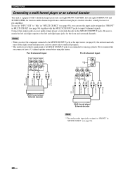
... turns off the digital sound field processor, and you cannot select sound field programs. • This unit does not redirect signals input at least a 5.1-channel speaker system before using this feature. For 6-channel input For 8-channel input CENTER FRONT(6CH) SURROUND L R SUB WOOFER SB(8CH) MULTI CH INPUT () ( C) ...signals. Connect the output jacks on your multi-format player or external decoder to the left and right SURROUND and SUBWOOFER) for missing speakers. We recommend that you can use the input jacks assigned as "FRONT" in MULTI CH SET (see page 96). 26 En Be...
... turns off the digital sound field processor, and you cannot select sound field programs. • This unit does not redirect signals input at least a 5.1-channel speaker system before using this feature. For 6-channel input For 8-channel input CENTER FRONT(6CH) SURROUND L R SUB WOOFER SB(8CH) MULTI CH INPUT () ( C) ...signals. Connect the output jacks on your multi-format player or external decoder to the left and right SURROUND and SUBWOOFER) for missing speakers. We recommend that you can use the input jacks assigned as "FRONT" in MULTI CH SET (see page 96). 26 En Be...

MCXSP10 Manual
Page 34
... unit turns on, and the advanced setup menu appears in the front panel display. The following display appears in the front panel display. PROGRAM SPEAKER IMP. 8 MIN 30 En STRAIGHT EFFECT While holding down MASTER 3 Rotate the PROGRAM selector on the front panel to save the new setting ... then press MASTER ON/OFF inward to the ON position to "6ΩMIN" as follows BEFORE using this unit. 4 ohm speakers can be also used as the front speakers. (U.S.A. to turn on this unit. STRAIGHT EFFECT MAIN ZONE ON/OFF ON OFF MASTER INPUT AUDIO SELECT TONE CONTROL A/B/C/D/E CATEGORY...
... unit turns on, and the advanced setup menu appears in the front panel display. The following display appears in the front panel display. PROGRAM SPEAKER IMP. 8 MIN 30 En STRAIGHT EFFECT While holding down MASTER 3 Rotate the PROGRAM selector on the front panel to save the new setting ... then press MASTER ON/OFF inward to the ON position to "6ΩMIN" as follows BEFORE using this unit. 4 ohm speakers can be also used as the front speakers. (U.S.A. to turn on this unit. STRAIGHT EFFECT MAIN ZONE ON/OFF ON OFF MASTER INPUT AUDIO SELECT TONE CONTROL A/B/C/D/E CATEGORY...

MCXSP10 Manual
Page 36
... optimizer microphone to affix the optimizer microphone at your actual listening environment. AUTO SETUP AUTO SETUP This unit employs the YPAO (YAMAHA Parametric Room Acoustic Optimizer) technology which lets you have connected the supplied optimizer microphone to the OPTIMIZER MIC jack on the front... the omni-directional microphone heading upward. You can be satisfactory. The supplied optimizer microphone collects and this unit analyzes the sound your speakers produce in "TROUBLESHOOTING" on pages 128 and 129 for a complete list of your listening room, run "AUTO SETUP" using the...
... optimizer microphone to affix the optimizer microphone at your actual listening environment. AUTO SETUP AUTO SETUP This unit employs the YPAO (YAMAHA Parametric Room Acoustic Optimizer) technology which lets you have connected the supplied optimizer microphone to the OPTIMIZER MIC jack on the front... the omni-directional microphone heading upward. You can be satisfactory. The supplied optimizer microphone collects and this unit analyzes the sound your speakers produce in "TROUBLESHOOTING" on pages 128 and 129 for a complete list of your listening room, run "AUTO SETUP" using the...
MCXSP10 Manual
Page 37
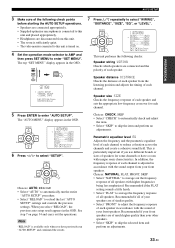
...;;;;;;CHECK START [ ]/[ ]:Up/Down [p]/[[]:Select This unit performs the following check points before starting the AUTO SETUP operations. • Speakers are connected appropriately. • Supplied optimizer microphone is connected to this unit is turned on page 34 and carry out the operations....the previous auto setup result appears in the OSD. Note "RELOAD" is available only when you use different brands or sizes of speakers for each speaker in accordance with higher frequencies being less emphasized. Recommended if the FLAT setting sounds a little harsh. • Select "FLAT"...
...;;;;;;CHECK START [ ]/[ ]:Up/Down [p]/[[]:Select This unit performs the following check points before starting the AUTO SETUP operations. • Speakers are connected appropriately. • Supplied optimizer microphone is connected to this unit is turned on page 34 and carry out the operations....the previous auto setup result appears in the OSD. Note "RELOAD" is available only when you use different brands or sizes of speakers for each speaker in accordance with higher frequencies being less emphasized. Recommended if the FLAT setting sounds a little harsh. • Select "FLAT"...

MCXSP10 Manual
Page 38
... order: Front/Back/Subwoofer Speaker distance DIST Displays the speaker distance from the listening position in the following order: Closest speaker distance/Farthest speaker distance Speaker level LVL Displays the speaker output level in the following order: Lowest speaker output level/Highest speaker output level Notes •...display appears in the auto setup procedure. AUTO SETUP Volume level LEVEL Checks and adjusts the volume level of speakers connected to complete the auto setup procedure. This unit starts the auto setup procedure. The display changes as follows. RESULT ....
... order: Front/Back/Subwoofer Speaker distance DIST Displays the speaker distance from the listening position in the following order: Closest speaker distance/Farthest speaker distance Speaker level LVL Displays the speaker output level in the following order: Lowest speaker output level/Highest speaker output level Notes •...display appears in the auto setup procedure. AUTO SETUP Volume level LEVEL Checks and adjusts the volume level of speakers connected to complete the auto setup procedure. This unit starts the auto setup procedure. The display changes as follows. RESULT ....


