
Owner's Manual
Page 4
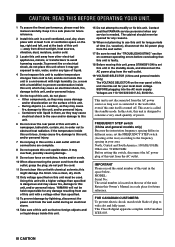
...from the AC power source as long as they may overheat, possibly causing damage. 9 Do not use of this unit must be used. Other components, as it is located on the rear of plug to wide slot and fully insert. Containers with high humidity (i.e. Use a clean, dry cloth....) Because the interstation frequency spacing differs in different areas, set this unit in a safe place for future reference. IIIVI CAUTION Contact qualified YAMAHA service personnel when any damage resulting from use force on switches, knobs and/or cords. 10 When disconnecting the power cord from the AC...
...from the AC power source as long as they may overheat, possibly causing damage. 9 Do not use of this unit must be used. Other components, as it is located on the rear of plug to wide slot and fully insert. Containers with high humidity (i.e. Use a clean, dry cloth....) Because the interstation frequency spacing differs in different areas, set this unit in a safe place for future reference. IIIVI CAUTION Contact qualified YAMAHA service personnel when any damage resulting from use force on switches, knobs and/or cords. 10 When disconnecting the power cord from the AC...
Owner's Manual
Page 5
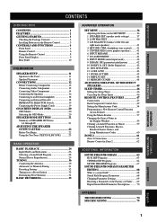
...Rear Panel 10 PREPARATION SPEAKER SETUP 11 Speakers to Be Used 11 Speaker Placement 11 CONNECTIONS 12 Before Connecting Components 12 Connecting Audio Components 12 Connecting Video Components 14 Connecting the Speakers 16 Connecting to an External Amplifier 18 Connecting an External Decoder 18 IMPEDANCE SELECTOR ... SLEEP TIMER 46 Setting the Sleep Timer 46 Canceling the Sleep Timer 46 REMOTE CONTROL FEATURES 47 Control Area 47 Each Component Control Area 49 Setting the Manufacturer Code 54 Programming a New Remote Control Function (Learn Feature 55 Using the Macro Feature...
...Rear Panel 10 PREPARATION SPEAKER SETUP 11 Speakers to Be Used 11 Speaker Placement 11 CONNECTIONS 12 Before Connecting Components 12 Connecting Audio Components 12 Connecting Video Components 14 Connecting the Speakers 16 Connecting to an External Amplifier 18 Connecting an External Decoder 18 IMPEDANCE SELECTOR ... SLEEP TIMER 46 Setting the Sleep Timer 46 Canceling the Sleep Timer 46 REMOTE CONTROL FEATURES 47 Control Area 47 Each Component Control Area 49 Setting the Manufacturer Code 54 Programming a New Remote Control Function (Learn Feature 55 Using the Macro Feature...
Owner's Manual
Page 6
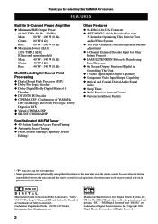
...symbol are trademarks of Digital Theater Systems, Inc. US Pat. "DTS", "DTS Digital Surround" and "DTS ES" are trademarks of YAMAHA DSP Technology and Dolby Pro Logic, Dolby Digital or DTS x Virtual CINEMA DSP x SILENT CINEMA DSP Sophisticated AM/FM Tuner x 40...x BASS EXTENSION Button for Reinforcing Bass Response x On Screen Display Function Helpful in Controlling This Unit x S Video Signal Input/Output Capability x Component Video Input/Output Capability x Optical and Coaxial Digital Audio Signal Jacks x Sleep Timer x Multi-Function Remote Control x Custom Installation Facility •...
...symbol are trademarks of Digital Theater Systems, Inc. US Pat. "DTS", "DTS Digital Surround" and "DTS ES" are trademarks of YAMAHA DSP Technology and Dolby Pro Logic, Dolby Digital or DTS x Virtual CINEMA DSP x SILENT CINEMA DSP Sophisticated AM/FM Tuner x 40...x BASS EXTENSION Button for Reinforcing Bass Response x On Screen Display Function Helpful in Controlling This Unit x S Video Signal Input/Output Capability x Component Video Input/Output Capability x Optical and Coaxial Digital Audio Signal Jacks x Sleep Timer x Multi-Function Remote Control x Custom Installation Facility •...
Owner's Manual
Page 10
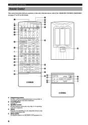
... page 47. D Others Functions vary depending on pages 47 to conveniently operates your other components. E Setup section Sets speaker output levels, SET MENU, DSP parameters, etc. 6 See "REMOTE CONTROL FEATURES" on your other components. A/B/C/D/E PRESET + TV INPUT CH TV MUTE - DISC MUTE EFFECT + VOLUME - .... CONTROLS AND FUNCTIONS Remote Control This section describes the basic operation of programming types you can utilize to 60 for operating your components that are set up with the remote control. CHAPTER + POWER REC / STOP PAUSE PLAY 10KEY DSP HALL 1 HALL 2 ...
... page 47. D Others Functions vary depending on pages 47 to conveniently operates your other components. E Setup section Sets speaker output levels, SET MENU, DSP parameters, etc. 6 See "REMOTE CONTROL FEATURES" on your other components. A/B/C/D/E PRESET + TV INPUT CH TV MUTE - DISC MUTE EFFECT + VOLUME - .... CONTROLS AND FUNCTIONS Remote Control This section describes the basic operation of programming types you can utilize to 60 for operating your components that are set up with the remote control. CHAPTER + POWER REC / STOP PAUSE PLAY 10KEY DSP HALL 1 HALL 2 ...
Owner's Manual
Page 11
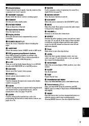
... remote control is turned off, all Dolby Digital and DTS audio signals except for the LFE channel are controlling. 7 SOURCE SELECT k/n Selects the source component without switching the input. 8 10KEY/DSP Selects the numeric button (10KEY) mode or DSP mode. 9 DSP program group/Numeric buttons Select DSP programs... or numbers according to the position of this unit. 5 Input selector buttons Select the input source. 6 Display window Shows the selected source component that group.) 0 6.1/ES Turns on -screen display (OSD) mode for control by a single button (see page 59). Aim this window at the...
... remote control is turned off, all Dolby Digital and DTS audio signals except for the LFE channel are controlling. 7 SOURCE SELECT k/n Selects the source component without switching the input. 8 10KEY/DSP Selects the numeric button (10KEY) mode or DSP mode. 9 DSP program group/Numeric buttons Select DSP programs... or numbers according to the position of this unit. 5 Input selector buttons Select the input source. 6 Display window Shows the selected source component that group.) 0 6.1/ES Turns on -screen display (OSD) mode for control by a single button (see page 59). Aim this window at the...
Owner's Manual
Page 14
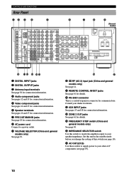
... IN OUT REMOTE CONTROL SUB CENTER WOOFER 6CH INPUT 100 kHz/10 kHz 50 kHz/ 9 kHz FM AM FREQUENCY STEP MONITOR OUT S VIDEO VIDEO VIDEO COMPONENT DVD Y PB/ CB PR/ CR D-TV/LD Y PB/ CB PR/ CR MONITOR OUT Y PB/ CB PR/ CR VIDEO + R A MAIN B CENTER + R + REAR (SURROUND) -... r ZONE 2 OUT jacks See page 61 for details. u AC OUTLET(S) Use these outlets to supply power to your other A/V components (see page 19). q REMOTE CONTROL IN/OUT jacks See page 61 for details. Consult your speaker impedance. Set this unit in the standby mode before...
... IN OUT REMOTE CONTROL SUB CENTER WOOFER 6CH INPUT 100 kHz/10 kHz 50 kHz/ 9 kHz FM AM FREQUENCY STEP MONITOR OUT S VIDEO VIDEO VIDEO COMPONENT DVD Y PB/ CB PR/ CR D-TV/LD Y PB/ CB PR/ CR MONITOR OUT Y PB/ CB PR/ CR VIDEO + R A MAIN B CENTER + R + REAR (SURROUND) -... r ZONE 2 OUT jacks See page 61 for details. u AC OUTLET(S) Use these outlets to supply power to your other A/V components (see page 19). q REMOTE CONTROL IN/OUT jacks See page 61 for details. Consult your speaker impedance. Set this unit in the standby mode before...
Owner's Manual
Page 16
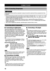
... You can designate the input for each component to be connected to this unit. • When you connect other components. • When you record from a source component connected to this unit while this unit may distort the sound from other YAMAHA audio components (such as a tape deck, MD recorder...I /O ASSIGNMENT" on the SET MENU (see page 41 for direct transmission of digital signals through either coaxial or fiber optic cables. Some components require different connection methods and have a turntable with a low-output MC cartridge, use a fiber optic cable that is given to the EIA...
... You can designate the input for each component to be connected to this unit. • When you connect other components. • When you record from a source component connected to this unit while this unit may distort the sound from other YAMAHA audio components (such as a tape deck, MD recorder...I /O ASSIGNMENT" on the SET MENU (see page 41 for direct transmission of digital signals through either coaxial or fiber optic cables. Some components require different connection methods and have a turntable with a low-output MC cartridge, use a fiber optic cable that is given to the EIA...

Owner's Manual
Page 17
... OUTPUT L R C COAXIAL OUTPUT DIGITAL OUTPUT MD/ TAPE TUNER AM CD-R ANT OPTICAL GND AUDIO R L IN (PLAY) MD/TAPE OUT (REC) AUDIO R L S VIDEO DVD VIDEO VIDEO COMPONENT DVD Y D-TV PB/ /LD CB CD IN (PLAY) CBL PR/ /SAT CR CD-R 75 UNBAL. ADVANCED OPERATION ADDITIONAL INFORMATION APPENDIX English 13
... OUTPUT L R C COAXIAL OUTPUT DIGITAL OUTPUT MD/ TAPE TUNER AM CD-R ANT OPTICAL GND AUDIO R L IN (PLAY) MD/TAPE OUT (REC) AUDIO R L S VIDEO DVD VIDEO VIDEO COMPONENT DVD Y D-TV PB/ /LD CB CD IN (PLAY) CBL PR/ /SAT CR CD-R 75 UNBAL. ADVANCED OPERATION ADDITIONAL INFORMATION APPENDIX English 13
Owner's Manual
Page 18
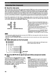
...Notes • Use a commercially available S-video cable when connecting to the S VIDEO jack, and commercially available video cables when connecting to the COMPONENT VIDEO jacks. • When you can connect it to this unit gives priority to the S-video signal. • You can designate the input... the Dolby Digital RF (AC-3) signals, set the input mode to make S-video connections to this unit. Video signals input through the COMPONENT VIDEO jacks are made, this unit. You must playback an LD encoded with Dolby Digital signals in picture reproduction. Video signals input through...
...Notes • Use a commercially available S-video cable when connecting to the S VIDEO jack, and commercially available video cables when connecting to the COMPONENT VIDEO jacks. • When you can connect it to this unit gives priority to the S-video signal. • You can designate the input... the Dolby Digital RF (AC-3) signals, set the input mode to make S-video connections to this unit. Video signals input through the COMPONENT VIDEO jacks are made, this unit. You must playback an LD encoded with Dolby Digital signals in picture reproduction. Video signals input through...
Owner's Manual
Page 19
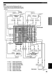
...indicates video cables S indicates S-video cables V S VIDEO S VIDEO INPUT INPUT Video monitor COMPONENT INPUT 15 APPENDIX English RF OUTPUT OPTICAL LD player OUTPUT COMPONENT AUDIO OUTPUT OUTPUT TV/digital TV or LD player CONNECTIONS OPTICAL OUTPUT AUDIO OUTPUT DVD player...OUTPUT S VIDEO V OUTPUT PREPARATION BASIC OPERATION ADVANCED OPERATION ADDITIONAL INFORMATION DIGITAL OUTPUT MD/ TAPE TUNER AUDIO R L AUDIO R L S VIDEO VIDEO VIDEO COMPONENT DVD (General model) L IN (PLAY) DVD Y AM MD/TAPE R CD-R ANT OUT (REC) D-TV PB/ /LD CB OPTICAL GND...
...indicates video cables S indicates S-video cables V S VIDEO S VIDEO INPUT INPUT Video monitor COMPONENT INPUT 15 APPENDIX English RF OUTPUT OPTICAL LD player OUTPUT COMPONENT AUDIO OUTPUT OUTPUT TV/digital TV or LD player CONNECTIONS OPTICAL OUTPUT AUDIO OUTPUT DVD player...OUTPUT S VIDEO V OUTPUT PREPARATION BASIC OPERATION ADVANCED OPERATION ADDITIONAL INFORMATION DIGITAL OUTPUT MD/ TAPE TUNER AUDIO R L AUDIO R L S VIDEO VIDEO VIDEO COMPONENT DVD (General model) L IN (PLAY) DVD Y AM MD/TAPE R CD-R ANT OUT (REC) D-TV PB/ /LD CB OPTICAL GND...
Owner's Manual
Page 23
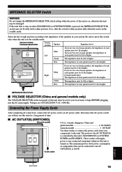
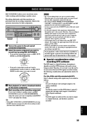
... impedance of the speakers in the standby mode. Disconnect the AC power cord if you use this unit fails to this unit is in your components to turn on when STANDBY/ON (or SYSTEM POWER) is pressed, the IMPEDANCE SELECTOR switch may be 8 Ω or higher. Select the left or ...right position according to an AC power outlet. The maximum power (total power consumption of components) that can be 8 Ω or higher. If you will supply power to any connected component whenever this unit is on, otherwise the unit may not be fully slid to the AC OUTLET(S) is...
... impedance of the speakers in the standby mode. Disconnect the AC power cord if you use this unit fails to this unit is in your components to turn on when STANDBY/ON (or SYSTEM POWER) is pressed, the IMPEDANCE SELECTOR switch may be 8 Ω or higher. Select the left or ...right position according to an AC power outlet. The maximum power (total power consumption of components) that can be 8 Ω or higher. If you will supply power to any connected component whenever this unit is on, otherwise the unit may not be fully slid to the AC OUTLET(S) is...
Owner's Manual
Page 24
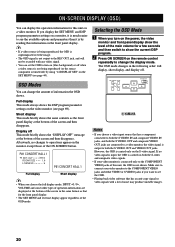
... the level of noise may produce unstable images. 20 If no changes to change the amount of this unit, the OSD is output to the COMPONENT VIDEO jacks of information the OSD shows. Make sure to connect your video monitor is by using "14 DISPLAY SET" on a video monitor. ... as the front panel display at the bottom of the screen and then disappears. y • If a video source is being reproduced (or the source component is much easier to see page 69). OSD Modes You can display the operation information for this information on the front panel display. Selecting the...
... the level of noise may produce unstable images. 20 If no changes to change the amount of this unit, the OSD is output to the COMPONENT VIDEO jacks of information the OSD shows. Make sure to connect your video monitor is by using "14 DISPLAY SET" on a video monitor. ... as the front panel display at the bottom of the screen and then disappears. y • If a video source is being reproduced (or the source component is much easier to see page 69). OSD Modes You can display the operation information for this information on the front panel display. Selecting the...
Owner's Manual
Page 28
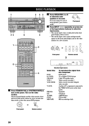
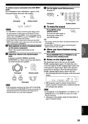
...input source Select this: DVD: D-TV/LD: CBL/SAT: VCR 1: VCR 2/DVR: V-AUX: PHONO: CD: TUNER: CD-R: MD/TAPE: To reproduce the signal from this component DVD player TV or digital TV/LD player Cable TV/satellite tuner Video cassette recorder 1 Video cassette recorder 2/digital video recorder Another... A/V component (connected to turn on the front panel) Turntable CD player AM/FM tuner CD recorder MD recorder/tape deck Front panel Remote control 24 ...
...input source Select this: DVD: D-TV/LD: CBL/SAT: VCR 1: VCR 2/DVR: V-AUX: PHONO: CD: TUNER: CD-R: MD/TAPE: To reproduce the signal from this component DVD player TV or digital TV/LD player Cable TV/satellite tuner Video cassette recorder 1 Video cassette recorder 2/digital video recorder Another... A/V component (connected to turn on the front panel) Turntable CD player AM/FM tuner CD recorder MD recorder/tape deck Front panel Remote control 24 ...
Owner's Manual
Page 29
... with a video source, first select the video source and then press 6CH INPUT. 4 Start playback (or select a broadcast station) on the source component. BASIC PLAYBACK 6 Use the digital sound field processor. TV CONCERT STADIUM TAINMENT SPORTS 5 6 7 8 MONO MOVIE 9 MOVIE MOVIE THEATER 1 THEATER ... from the subwoofer. 3. Front panel BASS TREBLE Remote control BASS PROCESSOR EXTENSION DIRECT - +- + ON OFF Front panel Note • If the component connected to SMALL or "1E LFE/BASS OUT" is set this unit: 1. VOLUME + or VOLUME - PROGRAM 10KEY DSP HALL 1 HALL 2 ...
... with a video source, first select the video source and then press 6CH INPUT. 4 Start playback (or select a broadcast station) on the source component. BASIC PLAYBACK 6 Use the digital sound field processor. TV CONCERT STADIUM TAINMENT SPORTS 5 6 7 8 MONO MOVIE 9 MOVIE MOVIE THEATER 1 THEATER ... from the subwoofer. 3. Front panel BASS TREBLE Remote control BASS PROCESSOR EXTENSION DIRECT - +- + ON OFF Front panel Note • If the component connected to SMALL or "1E LFE/BASS OUT" is set this unit: 1. VOLUME + or VOLUME - PROGRAM 10KEY DSP HALL 1 HALL 2 ...
Owner's Manual
Page 30
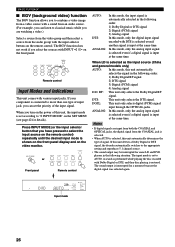
... a sound from an audio source. (For example, you can listen to classical music while you can set the priority of the input signal. If your component is set according to "8 INPUT MODE" on the front panel.
... a sound from an audio source. (For example, you can listen to classical music while you can set the priority of the input signal. If your component is set according to "8 INPUT MODE" on the front panel.
Owner's Manual
Page 31
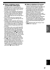
... a DTS signal with the input mode setting left to AUTO, this unit automatically switches to the "DTS-decoding" mode to PCM or analog. • Some A/V components such as necessary. • While you are operating the LD player and playing a disc encoded with a Dolby Digital signal, if you switch from being generated...
... a DTS signal with the input mode setting left to AUTO, this unit automatically switches to the "DTS-decoding" mode to PCM or analog. • Some A/V components such as necessary. • While you are operating the LD player and playing a disc encoded with a Dolby Digital signal, if you switch from being generated...
Owner's Manual
Page 39
...8226; S-video and composite video signals pass independently through this unit cannot be made. Attempting to the operation instructions for these components. INTRODUCTION PREPARATION BASIC OPERATION BASIC RECORDING REC OUT/ZONE 2 allows you cannot record between other operations are performed from by your ... audio and video from records, CDs, radio, etc. Therefore, when recording or dubbing video signals, if your video source component is a digital bitstream. Therefore, if you want to reproduce with DTS Only 2-channel analog audio signals may be recorded. ...
...8226; S-video and composite video signals pass independently through this unit cannot be made. Attempting to the operation instructions for these components. INTRODUCTION PREPARATION BASIC OPERATION BASIC RECORDING REC OUT/ZONE 2 allows you cannot record between other operations are performed from by your ... audio and video from records, CDs, radio, etc. Therefore, when recording or dubbing video signals, if your video source component is a digital bitstream. Therefore, if you want to reproduce with DTS Only 2-channel analog audio signals may be recorded. ...

Owner's Manual
Page 45
... and general models only)) to exit from the left main speaker. "TEST DOLBY SUR." Once you begin this feature to designate the input for the COMPONENT jacks (A and B) and the DIGITAL INPUT/OUTPUT jacks (1 to 8 (or 9 for 5-band 1 Press n to select a higher frequency and k to select ...; You can use up to 8 characters to rename the inputs. 4 Press + repeatedly to any sources you adjust the various frequency levels. s 7A [A] [B] (for the COMPONENT VIDEO jacks) Initial settings: [A] DVD [B] D-TV/LD s 7B (1) (2) (for the OPTICAL OUTPUT jacks) Initial settings: (1) MD/TAPE (2) CD-R s 7C (3) to...
... and general models only)) to exit from the left main speaker. "TEST DOLBY SUR." Once you begin this feature to designate the input for the COMPONENT jacks (A and B) and the DIGITAL INPUT/OUTPUT jacks (1 to 8 (or 9 for 5-band 1 Press n to select a higher frequency and k to select ...; You can use up to 8 characters to rename the inputs. 4 Press + repeatedly to any sources you adjust the various frequency levels. s 7A [A] [B] (for the COMPONENT VIDEO jacks) Initial settings: [A] DVD [B] D-TV/LD s 7B (1) (2) (for the OPTICAL OUTPUT jacks) Initial settings: (1) MD/TAPE (2) CD-R s 7C (3) to...
Owner's Manual
Page 48
... (OSD off ). s DIMMER You can set the OSD background to blue if the video source is not being reproduced (or the power of the source component is off -set position) This setting is set to ON, you cannot use the test tone. • When "15 MEMORY GUARD" is used to adjust...
... (OSD off ). s DIMMER You can set the OSD background to blue if the video source is not being reproduced (or the power of the source component is off -set position) This setting is set to ON, you cannot use the test tone. • When "15 MEMORY GUARD" is used to adjust...
Owner's Manual
Page 50
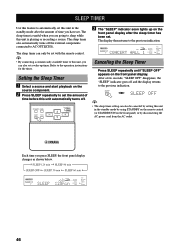
... after the amount of time before this unit automatically turns off. Setting the Sleep Timer 1 Select a source and start playback on the source component. 2 Press SLEEP repeatedly to set with the remote control. After a few seconds, "SLEEP OFF" disappears, the "SLEEP" indicator goes off the external... components connected to the previous indication. SLEEP TIMER Use this feature to automatically set this unit in the standby mode by using STANDBY on the ...
... after the amount of time before this unit automatically turns off. Setting the Sleep Timer 1 Select a source and start playback on the source component. 2 Press SLEEP repeatedly to set with the remote control. After a few seconds, "SLEEP OFF" disappears, the "SLEEP" indicator goes off the external... components connected to the previous indication. SLEEP TIMER Use this feature to automatically set this unit in the standby mode by using STANDBY on the ...


