

Owner's Manual
Page 2
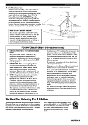
... service the unit beyond those means described in performance; The power-supply cord or the plug has been damaged; For example, the unit should be connected to a power supply only of electric shock to overturn. 7 Wall or Ceiling Mounting - Objects have fallen, or liquid has been spilled into the inside of...
... service the unit beyond those means described in performance; The power-supply cord or the plug has been damaged; For example, the unit should be connected to a power supply only of electric shock to overturn. 7 Wall or Ceiling Mounting - Objects have fallen, or liquid has been spilled into the inside of...
Owner's Manual
Page 3
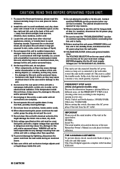
... 810-20) GROUNDING CONDUCTORS (NEC SECTION 810-21) GROUND CLAMPS POWER SERVICE GROUNDING ELECTRODE SYSTEM (NEC ART 250. IMPORTANT : When connecting this unit, be used according to the instructions found to be the source of your authority, granted by the FCC, to those products...2. If you to eliminate the problem by the interference. We Want You Listening For A Lifetime YAMAHA and the Electronic Industries Association's Consumer Electronics Group want you can be connected to the grounding system of other electronic devices. This product, when installed as close to the operation...
... 810-20) GROUNDING CONDUCTORS (NEC SECTION 810-21) GROUND CLAMPS POWER SERVICE GROUNDING ELECTRODE SYSTEM (NEC ART 250. IMPORTANT : When connecting this unit, be used according to the instructions found to be the source of your authority, granted by the FCC, to those products...2. If you to eliminate the problem by the interference. We Want You Listening For A Lifetime YAMAHA and the Electronic Industries Association's Consumer Electronics Group want you can be connected to the grounding system of other electronic devices. This product, when installed as close to the operation...
Owner's Manual
Page 4
... located on this unit, and/or personal injury. IMPORTANT Please record the serial number of this unit in this unit to a wall outlet until all connections are 110/120/220/240 V AC, 50/60 Hz. a room with a humidifier) to prevent condensation inside this unit, which may cause fire, ...damage to this unit, and/or personal injury. - Using this unit with chemical solvents; Contact qualified YAMAHA service personnel when any reasons. 16 When not planning to use of this unit - FREQUENCY STEP switch (China and general models only) Because the ...
... located on this unit, and/or personal injury. IMPORTANT Please record the serial number of this unit in this unit to a wall outlet until all connections are 110/120/220/240 V AC, 50/60 Hz. a room with a humidifier) to prevent condensation inside this unit, which may cause fire, ...damage to this unit, and/or personal injury. - Using this unit with chemical solvents; Contact qualified YAMAHA service personnel when any reasons. 16 When not planning to use of this unit - FREQUENCY STEP switch (China and general models only) Because the ...
Owner's Manual
Page 5
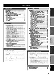
...to Be Used 11 Speaker Placement 11 CONNECTIONS 12 Before Connecting Components 12 Connecting Audio Components 12 Connecting Video Components 14 Connecting the Speakers 16 Connecting to an External Amplifier 18 Connecting an External Decoder 18 IMPEDANCE SELECTOR Switch 19 Connecting the Power Supply Cords 19 ON-SCREEN...Function or Macro 59 Clearing Learned Functions, Macros, Renamed Source Names, and Setup Manufacturer Codes 60 ZONE 2 61 Zone 2 Connections 61 Remote Control in Zone 2 62 ADDITIONAL INFORMATION SOUND FIELD PROGRAM 63 Hi-Fi DSP Programs 63 CINEMA DSP Programs 64 ...
...to Be Used 11 Speaker Placement 11 CONNECTIONS 12 Before Connecting Components 12 Connecting Audio Components 12 Connecting Video Components 14 Connecting the Speakers 16 Connecting to an External Amplifier 18 Connecting an External Decoder 18 IMPEDANCE SELECTOR Switch 19 Connecting the Power Supply Cords 19 ON-SCREEN...Function or Macro 59 Clearing Learned Functions, Macros, Renamed Source Names, and Setup Manufacturer Codes 60 ZONE 2 61 Zone 2 Connections 61 Remote Control in Zone 2 62 ADDITIONAL INFORMATION SOUND FIELD PROGRAM 63 Hi-Fi DSP Programs 63 CINEMA DSP Programs 64 ...
Owner's Manual
Page 8
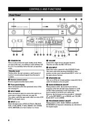
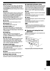
... this unit in the standby mode. When you do not use a subwoofer. This does not affect the REC OUT level. 7 6CH INPUT Selects the source connected to SWFR. 0 PROCESSOR DIRECT ON/OFF When pushed in (ON), BASS, TREBLE, and BASS EXTENSION are bypassed, eliminating any alteration of the original signal....However, this boost may not be a 4 to or watch. 6 VOLUME Controls the output level of all audio channels. This boost is set of main speakers connected to this unit (see page 9). 4 INPUT MODE Selects the mode of input for sources that send two or more types of signals to the A and...
... this unit in the standby mode. When you do not use a subwoofer. This does not affect the REC OUT level. 7 6CH INPUT Selects the source connected to SWFR. 0 PROCESSOR DIRECT ON/OFF When pushed in (ON), BASS, TREBLE, and BASS EXTENSION are bypassed, eliminating any alteration of the original signal....However, this boost may not be a 4 to or watch. 6 VOLUME Controls the output level of all audio channels. This boost is set of main speakers connected to this unit (see page 9). 4 INPUT MODE Selects the mode of input for sources that send two or more types of signals to the A and...
Owner's Manual
Page 9
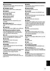
... the low-frequency response. ADVANCED OPERATION ADDITIONAL INFORMATION APPENDIX English 5 w EFFECT Switches the effect speakers (center, rear and rear center (see page 28). When you connect headphones, no signals are not operating the controls behind the front panel door, close the door. u VIDEO AUX jacks Inputs audio and video signals from...
... the low-frequency response. ADVANCED OPERATION ADDITIONAL INFORMATION APPENDIX English 5 w EFFECT Switches the effect speakers (center, rear and rear center (see page 28). When you connect headphones, no signals are not operating the controls behind the front panel door, close the door. u VIDEO AUX jacks Inputs audio and video signals from...
Owner's Manual
Page 11
... the power of this button after you want to operate. 2 TRANSMIT indicator Flashes while the remote control is turned off . i 6CH INPUT Selects the source connected to show the setup buttons. s Cover Slides down to the 6CH INPUT jacks. g SLEEP Sets the sleep timer. j PARAMETER/SET MENU Selects the PARAMETER mode...
... the power of this button after you want to operate. 2 TRANSMIT indicator Flashes while the remote control is turned off . i 6CH INPUT Selects the source connected to show the setup buttons. s Cover Slides down to the 6CH INPUT jacks. g SLEEP Sets the sleep timer. j PARAMETER/SET MENU Selects the PARAMETER mode...

Owner's Manual
Page 13
...-R TUNER CD PHONO 0q we r t yui 1 t indicator Lights up when the built-in DTS decoder is on . " g " lights up when both sets of speakers are connected. r Multi-information display Shows the current DSP program name and other information when adjusting or changing settings. Both indicators light up when the builtin Dolby...
...-R TUNER CD PHONO 0q we r t yui 1 t indicator Lights up when the built-in DTS decoder is on . " g " lights up when both sets of speakers are connected. r Multi-information display Shows the current DSP program name and other information when adjusting or changing settings. Both indicators light up when the builtin Dolby...
Owner's Manual
Page 14
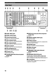
...input terminals See page 30 for connection information. 4 Audio component jacks See pages 12 and 13 for connection information. 5 Video component jacks See pages 14 and 15 for connection information. 6 Speaker terminals See pages 16 and 17 for connection information. 7 PRE OUT/MAIN IN...R L MAIN IN MAIN OUT AC OUTLETS SWITCHED 100W MAX. w RS-232C connector This is a control expansion connector for connection information. 8 AC power cord Connect to your dealer for connection information. r ZONE 2 OUT jacks See page 61 for details. t FREQUENCY STEP switch (China and general models only) ...
...input terminals See page 30 for connection information. 4 Audio component jacks See pages 12 and 13 for connection information. 5 Video component jacks See pages 14 and 15 for connection information. 6 Speaker terminals See pages 16 and 17 for connection information. 7 PRE OUT/MAIN IN...R L MAIN IN MAIN OUT AC OUTLETS SWITCHED 100W MAX. w RS-232C connector This is a control expansion connector for connection information. 8 AC power cord Connect to your dealer for connection information. r ZONE 2 OUT jacks See page 61 for details. t FREQUENCY STEP switch (China and general models only) ...
Owner's Manual
Page 16
... digital jacks for each digital jack according to these jacks. This cap protects the jack from other YAMAHA audio components (such as a tape deck, MD recorder and CD player or changer), connect them again to make sure they are correct. You can designate the input for each component to ... CD jacks, priority is given to the input signals from a source such as !, #, $ etc. YAMAHA applies this labeling system to all its power on the SET MENU (see page 41 for connecting a turntable with the same number labels as a CD or DVD are made correctly, that does not conform...
... digital jacks for each digital jack according to these jacks. This cap protects the jack from other YAMAHA audio components (such as a tape deck, MD recorder and CD player or changer), connect them again to make sure they are correct. You can designate the input for each component to ... CD jacks, priority is given to the input signals from a source such as !, #, $ etc. YAMAHA applies this labeling system to all its power on the SET MENU (see page 41 for connecting a turntable with the same number labels as a CD or DVD are made correctly, that does not conform...

Owner's Manual
Page 17
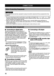
INTRODUCTION PREPARATION BASIC OPERATION OPTICAL INPUT MD recorder or tape deck INPUT LR OUTPUT LR OPTICAL INPUT CD recorder CONNECTIONS OPTICAL OUTPUT OUTPUT O LR INPUT LR O OPTICAL OUTPUT O CD player OUTPUT L R C COAXIAL OUTPUT DIGITAL OUTPUT MD/ TAPE TUNER AM CD-R ANT OPTICAL GND AUDIO R L IN (...
INTRODUCTION PREPARATION BASIC OPERATION OPTICAL INPUT MD recorder or tape deck INPUT LR OUTPUT LR OPTICAL INPUT CD recorder CONNECTIONS OPTICAL OUTPUT OUTPUT O LR INPUT LR O OPTICAL OUTPUT O CD player OUTPUT L R C COAXIAL OUTPUT DIGITAL OUTPUT MD/ TAPE TUNER AM CD-R ANT OPTICAL GND AUDIO R L IN (...
Owner's Manual
Page 18
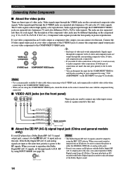
... the input for the COMPONENT VIDEO A and B jacks according to your LD player has a Dolby Digital RF (AC-3) signal output jack, connect it is given to the COMPONENT VIDEO jacks. Video signals input through the composite video, S-video and component jacks are input at the same time..., priority is not necessary to make S-video connections to this unit, it to the COMPONENT VIDEO jacks. • When you cannot reproduce Dolby Digital sound from an LD player, be different...
... the input for the COMPONENT VIDEO A and B jacks according to your LD player has a Dolby Digital RF (AC-3) signal output jack, connect it is given to the COMPONENT VIDEO jacks. Video signals input through the composite video, S-video and component jacks are input at the same time..., priority is not necessary to make S-video connections to this unit, it to the COMPONENT VIDEO jacks. • When you cannot reproduce Dolby Digital sound from an LD player, be different...
Owner's Manual
Page 19
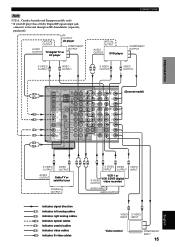
INTRODUCTION Note (U.S.A., Canada, Australia and Singapore models only) • If your LD player has a Dolby Digital RF signal output jack, connect it to this unit through an RF demodulator (separately purchased). CD-R FM ANT OUT (REC) D-TV/LD IN Y DVD O GND.../ CB D-TV /LD O PHONO OPTICAL COAXIAL RS- RF OUTPUT OPTICAL LD player OUTPUT COMPONENT AUDIO OUTPUT OUTPUT TV/digital TV or LD player CONNECTIONS OPTICAL OUTPUT AUDIO OUTPUT DVD player COMPONENT OUTPUT S VIDEO OUTPUT S VIDEO V OUTPUT LR S VIDEO OUTPUT S VIDEO V OUTPUT PREPARATION BASIC OPERATION ...
INTRODUCTION Note (U.S.A., Canada, Australia and Singapore models only) • If your LD player has a Dolby Digital RF signal output jack, connect it to this unit through an RF demodulator (separately purchased). CD-R FM ANT OUT (REC) D-TV/LD IN Y DVD O GND.../ CB D-TV /LD O PHONO OPTICAL COAXIAL RS- RF OUTPUT OPTICAL LD player OUTPUT COMPONENT AUDIO OUTPUT OUTPUT TV/digital TV or LD player CONNECTIONS OPTICAL OUTPUT AUDIO OUTPUT DVD player COMPONENT OUTPUT S VIDEO OUTPUT S VIDEO V OUTPUT LR S VIDEO OUTPUT S VIDEO V OUTPUT PREPARATION BASIC OPERATION ...

Owner's Manual
Page 20
...bare speaker wires touch each of the speaker cables. 2 Twist the exposed wires of each terminal. 3 Tighten the knob to these terminals. CONNECTIONS Connecting the Speakers Be sure to the number and size of the MAIN A or B terminals. First, tighten the knob and then insert the ...A center speaker can be unnatural and lack bass. y (U.S.A., Canada, Australia, China and general models only) • Banana plug connections are faulty, no sound will be connected to secure the wire. s REAR SPEAKERS terminals A rear speaker system can be heard from each other and do not let them ...
...bare speaker wires touch each of the speaker cables. 2 Twist the exposed wires of each terminal. 3 Tighten the knob to these terminals. CONNECTIONS Connecting the Speakers Be sure to the number and size of the MAIN A or B terminals. First, tighten the knob and then insert the ...A center speaker can be unnatural and lack bass. y (U.S.A., Canada, Australia, China and general models only) • Banana plug connections are faulty, no sound will be connected to secure the wire. s REAR SPEAKERS terminals A rear speaker system can be heard from each other and do not let them ...

Owner's Manual
Page 21
... Rear speakers Power amplifier Subwoofer connection See "SUBWOOFER jack" on this unit to the input jack on the separately prepared power amplifier. 2 Connect the rear center speaker to NONE (see page 39). Connecting the rear center speaker 1 Connect the PRE OUT REAR CENTER...100W MAX. Main speakers A Main speakers B Right Left Right VOLTAGE SELECTOR + R A MAIN B CENTER + - INTRODUCTION PREPARATION BASIC OPERATION CONNECTIONS s Using the rear center speaker You can enjoy the Dolby Digital Surround EX software or DTS ES software by adding the rear center speaker to...
... Rear speakers Power amplifier Subwoofer connection See "SUBWOOFER jack" on this unit to the input jack on the separately prepared power amplifier. 2 Connect the rear center speaker to NONE (see page 39). Connecting the rear center speaker 1 Connect the PRE OUT REAR CENTER...100W MAX. Main speakers A Main speakers B Right Left Right VOLTAGE SELECTOR + R A MAIN B CENTER + - INTRODUCTION PREPARATION BASIC OPERATION CONNECTIONS s Using the rear center speaker You can enjoy the Dolby Digital Surround EX software or DTS ES software by adding the rear center speaker to...

Owner's Manual
Page 22
...4 REAR (SURROUND) jacks Rear channel line output jacks. 5 SUBWOOFER jack When using a subwoofer with built-in amplifier, including the YAMAHA Active Servo Processing Subwoofer System, connect the input jack of this jack is 90 Hz.) The LFE (low-frequency effect) signals generated when Dolby Digital or DTS is ...INPUT jacks. The subwoofer volume cannot be adjusted from this unit's main channel amplifiers. • MAIN OUT jack Main channel line output jacks. Connecting an External Decoder This unit is not affected. 18 Note • When RCA pin plugs are directed to this jack. (The cut-off...
...4 REAR (SURROUND) jacks Rear channel line output jacks. 5 SUBWOOFER jack When using a subwoofer with built-in amplifier, including the YAMAHA Active Servo Processing Subwoofer System, connect the input jack of this jack is 90 Hz.) The LFE (low-frequency effect) signals generated when Dolby Digital or DTS is ...INPUT jacks. The subwoofer volume cannot be adjusted from this unit's main channel amplifiers. • MAIN OUT jack Main channel line output jacks. Connecting an External Decoder This unit is not affected. 18 Note • When RCA pin plugs are directed to this jack. (The cut-off...
Owner's Manual
Page 23
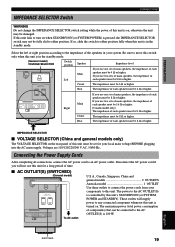
.../ON (or SYSTEM POWER and STANDBY). TOTAL IN T Center Rear The impedance must be 8 Ω or higher. Connecting the Power Supply Cords After completing all connections, connect the AC power cord to the AC OUTLET(S) is controlled by this unit is in the standby mode. (General model)...MIN. /SPEAKER REAR : 8 MIN. /SPEAKER To AC outlet U.S.A., Canada, Singapore, China and general models 2 OUTLETS Australia model 1 OUTLET Use these outlets to connect the power cords from your system. If this unit fails to turn on , otherwise the unit may not be fully slid to this unit must...
.../ON (or SYSTEM POWER and STANDBY). TOTAL IN T Center Rear The impedance must be 8 Ω or higher. Connecting the Power Supply Cords After completing all connections, connect the AC power cord to the AC OUTLET(S) is controlled by this unit is in the standby mode. (General model)...MIN. /SPEAKER REAR : 8 MIN. /SPEAKER To AC outlet U.S.A., Canada, Singapore, China and general models 2 OUTLETS Australia model 1 OUTLET Use these outlets to connect the power cords from your system. If this unit fails to turn on , otherwise the unit may not be fully slid to this unit must...
Owner's Manual
Page 24
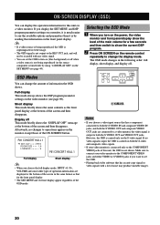
...SET MENU (see page 69). Selecting the OSD Mode 1 When you want to see the OSD. • Playing back video software that has a component connected to operations appear on the video monitor (see page 44). The OSD mode changes in the same format as the front panel display at the... seconds and then switch to show the level of noise may produce unstable images. 20 Make sure to connect your video monitor is connected only to the COMPONENT VIDEO jacks of operation information are connected to a video monitor, the video signal is turned off . If no changes to both the S VIDEO ...
...SET MENU (see page 69). Selecting the OSD Mode 1 When you want to see the OSD. • Playing back video software that has a component connected to operations appear on the video monitor (see page 44). The OSD mode changes in the same format as the front panel display at the... seconds and then switch to show the level of noise may produce unstable images. 20 Make sure to connect your video monitor is connected only to the COMPONENT VIDEO jacks of operation information are connected to a video monitor, the video signal is turned off . If no changes to both the S VIDEO ...
Owner's Manual
Page 26
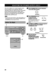
... BASS and TREBLE on the front panel to the center position and set PARAMETER/SET MENU on the remote control to PARAMETER. If you are connected to this unit, be sure to unplug the headphones from each speaker. Front panel 4 Sit in the listening position and set BASS EXTENSION to OFF...
... BASS and TREBLE on the front panel to the center position and set PARAMETER/SET MENU on the remote control to PARAMETER. If you are connected to this unit, be sure to unplug the headphones from each speaker. Front panel 4 Sit in the listening position and set BASS EXTENSION to OFF...
Owner's Manual
Page 27
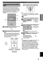
... (TEST LEFT) (TEST RIGHT) + VOLUME - While adjusting, the test tone is heard from the left rear speaker in the standby mode and check the speaker connections. 3 Press k / n repeatedly to select the speaker to be adjusted. 1 Press TEST to -10 dB, adjust the levels for a surround sound system. This setting decreases the...
... (TEST LEFT) (TEST RIGHT) + VOLUME - While adjusting, the test tone is heard from the left rear speaker in the standby mode and check the speaker connections. 3 Press k / n repeatedly to select the speaker to be adjusted. 1 Press TEST to -10 dB, adjust the levels for a surround sound system. This setting decreases the...


