

Owner's Manual
Page 1
Owner's Manual PRECAUTIONS pages 4 to 5 Setup pages 7 to 9 Troubleshooting pages 40 to 41 EN
Owner's Manual PRECAUTIONS pages 4 to 5 Setup pages 7 to 9 Troubleshooting pages 40 to 41 EN
Owner's Manual
Page 2
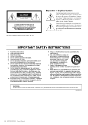
... lightning flash with the apparatus. WARNING TO REDUCE THE RISK OF FIRE OR ELECTRIC SHOCK, DO NOT EXPOSE THIS APPARATUS TO RAIN OR MOISTURE. (UL60065_03) 2 MGP32X/MGP24X Owner's Manual Servicing is required when the apparatus has been damaged in accor- dance with dry cloth. 7 Do not block any way, such as...
... lightning flash with the apparatus. WARNING TO REDUCE THE RISK OF FIRE OR ELECTRIC SHOCK, DO NOT EXPOSE THIS APPARATUS TO RAIN OR MOISTURE. (UL60065_03) 2 MGP32X/MGP24X Owner's Manual Servicing is required when the apparatus has been damaged in accor- dance with dry cloth. 7 Do not block any way, such as...
Owner's Manual
Page 3
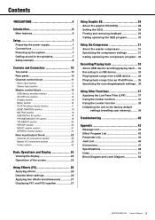
... Message List 42 Effect Program List 43 Parameter List 44 Jack List 46 Dimensions 47 Specifications 48 Index 51 Block Diagram and Level Diagram 52 MGP32X/MGP24X Owner's Manual 3
... Message List 42 Effect Program List 43 Parameter List 44 Jack List 46 Dimensions 47 Specifications 48 Index 51 Block Diagram and Level Diagram 52 MGP32X/MGP24X Owner's Manual 3
Owner's Manual
Page 4
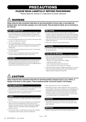
...basic precautions listed below to avoid the possibility of physical injury to you purchased, the included power cord may have the device inspected by Yamaha service personnel. - Inadequate ventilation can result in overheating, possibly causing damage to the device(s), or even fire. • Do not ...still flowing to the product at the bottom and sides to prevent the internal temperature from the AC outlet when cleaning the device. 4 MGP32X/MGP24X Owner's Manual PA_en_1 1/2 Connections • Before connecting the device to other than in an area other devices, turn off , electricity...
...basic precautions listed below to avoid the possibility of physical injury to you purchased, the included power cord may have the device inspected by Yamaha service personnel. - Inadequate ventilation can result in overheating, possibly causing damage to the device(s), or even fire. • Do not ...still flowing to the product at the bottom and sides to prevent the internal temperature from the AC outlet when cleaning the device. 4 MGP32X/MGP24X Owner's Manual PA_en_1 1/2 Connections • Before connecting the device to other than in an area other devices, turn off , electricity...
Owner's Manual
Page 5
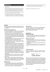
... iPhone may damage the speakers. • Do not apply oil, grease, or contact cleaner to believe that is reason to the faders. Yamaha cannot be saved to your computer or an external USB device. Connectors XLR-type connectors are wired as in direct sunlight, near ...iPhone, iPod, iPod classic, iPod nano, and iPod touch are the trademarks or registered trademarks of Apple Inc., registered in the U.S. PA_en_1 2/2 MGP32X/MGP24X Owner's Manual 5 When turning the power off, the power amplifier should also be held responsible for a long period of malfunction/damage to the...
... iPhone may damage the speakers. • Do not apply oil, grease, or contact cleaner to believe that is reason to the faders. Yamaha cannot be saved to your computer or an external USB device. Connectors XLR-type connectors are wired as in direct sunlight, near ...iPhone, iPod, iPod classic, iPod nano, and iPod touch are the trademarks or registered trademarks of Apple Inc., registered in the U.S. PA_en_1 2/2 MGP32X/MGP24X Owner's Manual 5 When turning the power off, the power amplifier should also be held responsible for a long period of malfunction/damage to the...
Owner's Manual
Page 6
... are called "knobs." REV-X and SPX Two powerful digital effect blocks are equipped with 8 COMP control knobs for purchasing the Yamaha MGP32X/MGP24X mixing console. The ducker function automatically lowers the level of background music to the right and want a more natural stereo image...variety of +48V phantom power and 26dB (pad) on the mono input channels features Xpressive EQ, which effectively models analog EQ utilizing Yamaha's famed VCM (Virtual Circuitry Modeling) technology. Independent toggle switching of effect applications, such as an audio file, and for playing ...
... are called "knobs." REV-X and SPX Two powerful digital effect blocks are equipped with 8 COMP control knobs for purchasing the Yamaha MGP32X/MGP24X mixing console. The ducker function automatically lowers the level of background music to the right and want a more natural stereo image...variety of +48V phantom power and 26dB (pad) on the mono input channels features Xpressive EQ, which effectively models analog EQ utilizing Yamaha's famed VCM (Virtual Circuitry Modeling) technology. Independent toggle switching of effect applications, such as an audio file, and for playing ...
Owner's Manual
Page 7
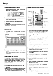
... meter indicator only occasionally rises above the "0" level. • The gain (volume) level of the STEREO master. 5. Adjust the overall volume with the PHONES knob. MGP32X/MGP24X Owner's Manual 7 Connect speakers, microphones and/or instru- NOTE • To use the mixer. Raise the STEREO master fader to avoid distortion. Powering up...
... meter indicator only occasionally rises above the "0" level. • The gain (volume) level of the STEREO master. 5. Adjust the overall volume with the PHONES knob. MGP32X/MGP24X Owner's Manual 7 Connect speakers, microphones and/or instru- NOTE • To use the mixer. Raise the STEREO master fader to avoid distortion. Powering up...

Owner's Manual
Page 8
Stage Power amp Powered subwoofer Powered monitor speakers (For musician monitoring) Microphone CH24 {CH16} (for talkback Lamp (Yamaha LA-1L) Powered monitor speakers Computer/Audio interface DVD player (voice) DJ mixer CD player Foyer etc. Setup Setup example Microphones for MC) Speakers Powered speakers Synthesizer 8 MGP32X/MGP24X Owner's Manual
Stage Power amp Powered subwoofer Powered monitor speakers (For musician monitoring) Microphone CH24 {CH16} (for talkback Lamp (Yamaha LA-1L) Powered monitor speakers Computer/Audio interface DVD player (voice) DJ mixer CD player Foyer etc. Setup Setup example Microphones for MC) Speakers Powered speakers Synthesizer 8 MGP32X/MGP24X Owner's Manual
Owner's Manual
Page 9
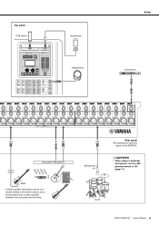
Microphone x 8 Rear panel *The illustrations show the panel of the MGP32X. CAUTION • When using a condenser microphone, set the +48V phantom switch to the mixer's inputs, use a DI box (direct box) or amp simulator between the instrument and the mixer. nected directly to ON (page 11). Drum MGP32X/MGP24X Owner's Manual 9 Top panel USB device iPod/iPhone Headphones Setup Compressor Instrument, Microphone Bass * If electric guitars and basses can be con-
Microphone x 8 Rear panel *The illustrations show the panel of the MGP32X. CAUTION • When using a condenser microphone, set the +48V phantom switch to the mixer's inputs, use a DI box (direct box) or amp simulator between the instrument and the mixer. nected directly to ON (page 11). Drum MGP32X/MGP24X Owner's Manual 9 Top panel USB device iPod/iPhone Headphones Setup Compressor Instrument, Microphone Bass * If electric guitars and basses can be con-

Owner's Manual
Page 10
... section (page 20) FX RTN (effect return) section (page 17) Channel I/O connectors section (page 22) Master I/O connectors section (page 22) Power section (page 23) 10 MGP32X/MGP24X Owner's Manual
... section (page 20) FX RTN (effect return) section (page 17) Channel I/O connectors section (page 22) Master I/O connectors section (page 22) Power section (page 23) 10 MGP32X/MGP24X Owner's Manual
Owner's Manual
Page 11
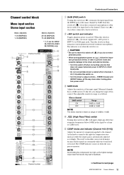
... is smoother, more phantom-powered condenser microphones. The COMP indicator comes on ( ) if you change the range of -34dB to next page MGP32X/MGP24X Owner's Manual 11 Channel number Continue to +10dB. CAUTION • Be sure to leave this control. e GAIN knob Adjusts ...STEREO master and GROUP faders- Controls and Connectors Channel control block Mono input section Stereo input section Mono channels 1-24 (MGP32X) 1-16 (MGP24X) Stereo channels 25-32 (MGP32X) 17-24 (MGP24X) * y-!0 are attenuated while the overall level is boosted. Turn it on when the compressor ...
... is smoother, more phantom-powered condenser microphones. The COMP indicator comes on ( ) if you change the range of -34dB to next page MGP32X/MGP24X Owner's Manual 11 Channel number Continue to +10dB. CAUTION • Be sure to leave this control. e GAIN knob Adjusts ...STEREO master and GROUP faders- Controls and Connectors Channel control block Mono input section Stereo input section Mono channels 1-24 (MGP32X) 1-16 (MGP24X) Stereo channels 25-32 (MGP32X) 17-24 (MGP24X) * y-!0 are attenuated while the overall level is boosted. Turn it on when the compressor ...

Owner's Manual
Page 12
...the tone of the stereo channel automatically when a signal exceeding a certain level is set at the center position. Channel number Channel number 12 MGP32X/MGP24X Owner's Manual y DUCKER SOURCE indicator The indicator of the selected input source (CH24 {CH16} or GROUP1) comes on ( ) ...turning to page 36. !0 STEREO IMAGE switch Selects the type of your iPod/iPhone. Controls and Connectors Mono channels 1-24 (MGP32X) 1-16 (MGP24X) Stereo channels 25-32 (MGP32X) 17-24 (MGP24X) * y-!0 are mixed at a fixed 2.5kHz center frequency. Band HIGH MID LOW Type Shelving Peaking ...
...the tone of the stereo channel automatically when a signal exceeding a certain level is set at the center position. Channel number Channel number 12 MGP32X/MGP24X Owner's Manual y DUCKER SOURCE indicator The indicator of the selected input source (CH24 {CH16} or GROUP1) comes on ( ) ...turning to page 36. !0 STEREO IMAGE switch Selects the type of your iPod/iPhone. Controls and Connectors Mono channels 1-24 (MGP32X) 1-16 (MGP24X) Stereo channels 25-32 (MGP32X) 17-24 (MGP24X) * y-!0 are mixed at a fixed 2.5kHz center frequency. Band HIGH MID LOW Type Shelving Peaking ...

Owner's Manual
Page 13
... be set close to the corresponding buses. NOTE To reduce noise, set the stereo pan position and determine the volume balance between the various channels. MGP32X/MGP24X Owner's Manual 13 NOTE • To enable use of AUX5 and AUX6, you turn all the way down. On stereo channels, the LINE L (odd...
... be set close to the corresponding buses. NOTE To reduce noise, set the stereo pan position and determine the volume balance between the various channels. MGP32X/MGP24X Owner's Manual 13 NOTE • To enable use of AUX5 and AUX6, you turn all the way down. On stereo channels, the LINE L (odd...

Owner's Manual
Page 14
Controls and Connectors Mono Channel Stereo Channel 1-2 3-4 ST AUX1 AUX2 AUX3 AUX4 14 MGP32X/MGP24X Owner's Manual
Controls and Connectors Mono Channel Stereo Channel 1-2 3-4 ST AUX1 AUX2 AUX3 AUX4 14 MGP32X/MGP24X Owner's Manual
Owner's Manual
Page 15
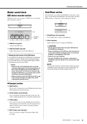
...of the capacity for the USB device is dedicated to the next song. Doing so may cause a notification sound to and recognized by Yamaha. (However, Yamaha cannot guarantee operation for all the way in the correct orientation or upside down. Avoid inserting with excessive force. Transport section...USB Cable for the iPod/iPhone connection. • When connecting to an iPod/iPhone, allow at least 6 seconds to the previous song. MGP32X/MGP24X Owner's Manual 15 q iPod/iPhone IN connector Use an USB cable to alternately start /stop recording. The supported file system is ...
...of the capacity for the USB device is dedicated to the next song. Doing so may cause a notification sound to and recognized by Yamaha. (However, Yamaha cannot guarantee operation for all the way in the correct orientation or upside down. Avoid inserting with excessive force. Transport section...USB Cable for the iPod/iPhone connection. • When connecting to an iPod/iPhone, allow at least 6 seconds to the previous song. MGP32X/MGP24X Owner's Manual 15 q iPod/iPhone IN connector Use an USB cable to alternately start /stop recording. The supported file system is ...
Owner's Manual
Page 16
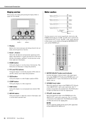
... clipping point. NOTE The PFL signal has display priority over the AFL signal when an input channel's PFL switch is for the functions on . 16 MGP32X/MGP24X Owner's Manual Meter section Knob 1 Knob 2 q Display Indicates the various messages and settings related to the output signal level of the STEREO OUT L/R and...
... clipping point. NOTE The PFL signal has display priority over the AFL signal when an input channel's PFL switch is for the functions on . 16 MGP32X/MGP24X Owner's Manual Meter section Knob 1 Knob 2 q Display Indicates the various messages and settings related to the output signal level of the STEREO OUT L/R and...
Owner's Manual
Page 17
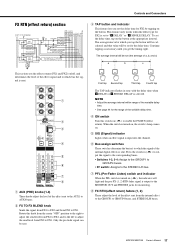
... the variable delay time. • See page 44 for FX2 by tapping on . Press the switch in sync with the delay time when , DELAY or . MGP32X/MGP24X Owner's Manual 17 Rotate this switch on /off, and determines the level of a, b, and c) a b c This section sets the effect returns (FX1 and FX2) on...
... the variable delay time. • See page 44 for FX2 by tapping on . Press the switch in sync with the delay time when , DELAY or . MGP32X/MGP24X Owner's Manual 17 Rotate this switch on /off, and determines the level of a, b, and c) a b c This section sets the effect returns (FX1 and FX2) on...

Owner's Manual
Page 18
..., the AFL indicator does not light, even if the AFL switch is the nominal level (0 dB). NOTE The "t" positions of the knobs for monitoring. 18 MGP32X/MGP24X Owner's Manual The signals from GROUP OUT and STEREO OUT. Controls and Connectors SEND MASTER section MATRIX section This section adjusts the levels and...
..., the AFL indicator does not light, even if the AFL switch is the nominal level (0 dB). NOTE The "t" positions of the knobs for monitoring. 18 MGP32X/MGP24X Owner's Manual The signals from GROUP OUT and STEREO OUT. Controls and Connectors SEND MASTER section MATRIX section This section adjusts the levels and...

Owner's Manual
Page 19
.... q PHONES jack Connect a pair of headphones to the MONITOR OUT jacks. e MONITOR knob Adjusts the level of the signal output to this TRS phone jack. MGP32X/MGP24X Owner's Manual 19 USB IN/iPod IN section Controls and Connectors PHONES/MONITOR section This section determines the destination of the signal output from...
.... q PHONES jack Connect a pair of headphones to the MONITOR OUT jacks. e MONITOR knob Adjusts the level of the signal output to this TRS phone jack. MGP32X/MGP24X Owner's Manual 19 USB IN/iPod IN section Controls and Connectors PHONES/MONITOR section This section determines the destination of the signal output from...
Owner's Manual
Page 20
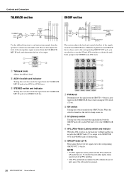
...-Fader Listen) switch and indictor When the AFL switch is on, the indicator will light and the signal after the GROUP fader (t) is pressed. 20 MGP32X/MGP24X Owner's Manual q Talkback knob Adjusts the talkback level. q PAN knob Determines how the signal from the TALKBACK MIC IN jack, and determines the bus...
...-Fader Listen) switch and indictor When the AFL switch is on, the indicator will light and the signal after the GROUP fader (t) is pressed. 20 MGP32X/MGP24X Owner's Manual q Talkback knob Adjusts the talkback level. q PAN knob Determines how the signal from the TALKBACK MIC IN jack, and determines the bus...
