

Owner's Manual
Page 1
Owner's Manual PRECAUTIONS pages 4 to 5 Setup pages 7 to 9 Troubleshooting pages 40 to 41 EN
Owner's Manual PRECAUTIONS pages 4 to 5 Setup pages 7 to 9 Troubleshooting pages 40 to 41 EN
Owner's Manual
Page 2
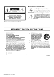
..., or has been dropped. WARNING TO REDUCE THE RISK OF FIRE OR ELECTRIC SHOCK, DO NOT EXPOSE THIS APPARATUS TO RAIN OR MOISTURE. (UL60065_03) 2 MGP32X/MGP24X Owner's Manual IMPORTANT SAFETY INSTRUCTIONS 1 Read these instructions. 2 Keep these instructions. 3 Heed all warnings. 4 Follow all instructions. 5 Do not use this apparatus during lightning storms or...
..., or has been dropped. WARNING TO REDUCE THE RISK OF FIRE OR ELECTRIC SHOCK, DO NOT EXPOSE THIS APPARATUS TO RAIN OR MOISTURE. (UL60065_03) 2 MGP32X/MGP24X Owner's Manual IMPORTANT SAFETY INSTRUCTIONS 1 Read these instructions. 2 Keep these instructions. 3 Heed all warnings. 4 Follow all instructions. 5 Do not use this apparatus during lightning storms or...
Owner's Manual
Page 3
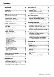
... Message List 42 Effect Program List 43 Parameter List 44 Jack List 46 Dimensions 47 Specifications 48 Index 51 Block Diagram and Level Diagram 52 MGP32X/MGP24X Owner's Manual 3
... Message List 42 Effect Program List 43 Parameter List 44 Jack List 46 Dimensions 47 Specifications 48 Index 51 Block Diagram and Level Diagram 52 MGP32X/MGP24X Owner's Manual 3
Owner's Manual
Page 4
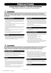
...; This device contains no user-serviceable parts. A burning item may come into the instrument. - Then have the device inspected by qualified Yamaha service personnel. • Never insert or remove an electric plug with a protective grounding connection. There is a sudden loss of sound during... abnormality • When one you intend to unplug the power cord from the AC outlet when cleaning the device. 4 MGP32X/MGP24X Owner's Manual PA_en_1 1/2 This device has ventilation holes at the minimum level. Inadequate ventilation can result in overheating, possibly causing damage to...
...; This device contains no user-serviceable parts. A burning item may come into the instrument. - Then have the device inspected by qualified Yamaha service personnel. • Never insert or remove an electric plug with a protective grounding connection. There is a sudden loss of sound during... abnormality • When one you intend to unplug the power cord from the AC outlet when cleaning the device. 4 MGP32X/MGP24X Owner's Manual PA_en_1 1/2 This device has ventilation holes at the minimum level. Inadequate ventilation can result in overheating, possibly causing damage to...
Owner's Manual
Page 5
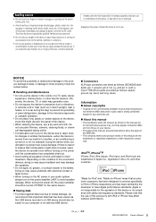
...) to believe that is not in use a dry and soft cloth. PA_en_1 2/2 MGP32X/MGP24X Owner's Manual 5 If you experience any gaps or openings on the device (vents, ports, etc.) If this manual are the trademarks or registered trademarks of panel disfiguration, damage to avoid speaker damage. ...8226; Copying of the commercially available musical data including but not limited to iPod or iPhone respectively, and has been certified by qualified Yamaha service personnel. • Do not rest your computer or an external USB device. Connectors XLR-type connectors are trademarks of...
...) to believe that is not in use a dry and soft cloth. PA_en_1 2/2 MGP32X/MGP24X Owner's Manual 5 If you experience any gaps or openings on the device (vents, ports, etc.) If this manual are the trademarks or registered trademarks of panel disfiguration, damage to avoid speaker damage. ...8226; Copying of the commercially available musical data including but not limited to iPod or iPhone respectively, and has been certified by qualified Yamaha service personnel. • Do not rest your computer or an external USB device. Connectors XLR-type connectors are trademarks of...
Owner's Manual
Page 6
...9-16. http://www.yamahaproaudio.com/global/en/products/peripherals/applications/mgp_editor/ Included Accessories • AC Power Cord • Owner's manual (this manual • Whenever there is a free software application that work together to a USB device as feedback. The head amplifier features...are distantly positioned, or when you a high-density, richly reverberant sound ambience, with 8 COMP control knobs for purchasing the Yamaha MGP32X/MGP24X mixing console. X-pressive EQ The shelving EQ (low/high) on another channel. Convenient, practical functions for eliminating the ...
...9-16. http://www.yamahaproaudio.com/global/en/products/peripherals/applications/mgp_editor/ Included Accessories • AC Power Cord • Owner's manual (this manual • Whenever there is a free software application that work together to a USB device as feedback. The head amplifier features...are distantly positioned, or when you a high-density, richly reverberant sound ambience, with 8 COMP control knobs for purchasing the Yamaha MGP32X/MGP24X mixing console. X-pressive EQ The shelving EQ (low/high) on another channel. Convenient, practical functions for eliminating the ...
Owner's Manual
Page 7
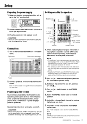
...; The gain (volume) level of the unit is adjusted with the STEREO master fader. Adjust the GAIN knobs so that can be too high. MGP32X/MGP24X Owner's Manual 7 GAIN knobs Power switch (rear panel) Faders 2. NOTE • To use the mixer. Adjust the overall volume with the PHONES knob. Connect speakers, microphones...
...; The gain (volume) level of the unit is adjusted with the STEREO master fader. Adjust the GAIN knobs so that can be too high. MGP32X/MGP24X Owner's Manual 7 GAIN knobs Power switch (rear panel) Faders 2. NOTE • To use the mixer. Adjust the overall volume with the PHONES knob. Connect speakers, microphones...

Owner's Manual
Page 8
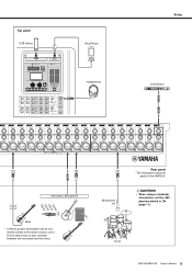
Stage Power amp Powered subwoofer Powered monitor speakers (For musician monitoring) Microphone CH24 {CH16} (for talkback Lamp (Yamaha LA-1L) Powered monitor speakers Computer/Audio interface DVD player (voice) DJ mixer CD player Foyer etc. Setup Setup example Microphones for MC) Speakers Powered speakers Synthesizer 8 MGP32X/MGP24X Owner's Manual
Stage Power amp Powered subwoofer Powered monitor speakers (For musician monitoring) Microphone CH24 {CH16} (for talkback Lamp (Yamaha LA-1L) Powered monitor speakers Computer/Audio interface DVD player (voice) DJ mixer CD player Foyer etc. Setup Setup example Microphones for MC) Speakers Powered speakers Synthesizer 8 MGP32X/MGP24X Owner's Manual
Owner's Manual
Page 9
Microphone x 8 Rear panel *The illustrations show the panel of the MGP32X. Drum MGP32X/MGP24X Owner's Manual 9 nected directly to ON (page 11). CAUTION • When using a condenser microphone, set the +48V phantom switch to the mixer's inputs, use a DI box (direct box) or amp simulator between the instrument and the mixer. Top panel USB device iPod/iPhone Headphones Setup Compressor Instrument, Microphone Bass * If electric guitars and basses can be con-
Microphone x 8 Rear panel *The illustrations show the panel of the MGP32X. Drum MGP32X/MGP24X Owner's Manual 9 nected directly to ON (page 11). CAUTION • When using a condenser microphone, set the +48V phantom switch to the mixer's inputs, use a DI box (direct box) or amp simulator between the instrument and the mixer. Top panel USB device iPod/iPhone Headphones Setup Compressor Instrument, Microphone Bass * If electric guitars and basses can be con-

Owner's Manual
Page 10
... section (page 20) FX RTN (effect return) section (page 17) Channel I/O connectors section (page 22) Master I/O connectors section (page 22) Power section (page 23) 10 MGP32X/MGP24X Owner's Manual
... section (page 20) FX RTN (effect return) section (page 17) Channel I/O connectors section (page 22) Master I/O connectors section (page 22) Power section (page 23) 10 MGP32X/MGP24X Owner's Manual
Owner's Manual
Page 11
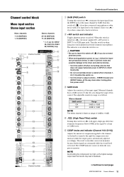
...order to prevent noise and possible damage to /from the INPUT jack of the input signal. As the knob is turned to next page MGP32X/MGP24X Owner's Manual 11 NOTE Avoid setting the compression too high, as follows. Turn this control. When this switch on ( ) if you have a 26dB... a slope of XLR input jacks. Controls and Connectors Channel control block Mono input section Stereo input section Mono channels 1-24 (MGP32X) 1-16 (MGP24X) Stereo channels 25-32 (MGP32X) 17-24 (MGP24X) * y-!0 are attenuated while the overall level is boosted. Turn it on when using one or more...
...order to prevent noise and possible damage to /from the INPUT jack of the input signal. As the knob is turned to next page MGP32X/MGP24X Owner's Manual 11 NOTE Avoid setting the compression too high, as follows. Turn this control. When this switch on ( ) if you have a 26dB... a slope of XLR input jacks. Controls and Connectors Channel control block Mono input section Stereo input section Mono channels 1-24 (MGP32X) 1-16 (MGP24X) Stereo channels 25-32 (MGP32X) 17-24 (MGP24X) * y-!0 are attenuated while the overall level is boosted. Turn it on when using one or more...

Owner's Manual
Page 12
If this switch on . Channel number Channel number 12 MGP32X/MGP24X Owner's Manual y DUCKER SOURCE indicator The indicator of the selected input source (CH24 {CH16} or GROUP1) comes on ( ) lowers the volume of the high, mid, and low ... changes the tone of the stereo channel automatically when a signal exceeding a certain level is on the display (page 37). Controls and Connectors Mono channels 1-24 (MGP32X) 1-16 (MGP24X) Stereo channels 25-32 (MGP32X) 17-24 (MGP24X) * y-!0 are mixed at the center position.
If this switch on . Channel number Channel number 12 MGP32X/MGP24X Owner's Manual y DUCKER SOURCE indicator The indicator of the selected input source (CH24 {CH16} or GROUP1) comes on ( ) lowers the volume of the high, mid, and low ... changes the tone of the stereo channel automatically when a signal exceeding a certain level is on the display (page 37). Controls and Connectors Mono channels 1-24 (MGP32X) 1-16 (MGP24X) Stereo channels 25-32 (MGP32X) 17-24 (MGP24X) * y-!0 are mixed at the center position.

Owner's Manual
Page 13
... or hard right, sound is turned on, the switch's lamp comes on ( ), the mixer feeds the pre-fader signal to the STEREO L and R buses. MGP32X/MGP24X Owner's Manual 13 Each knob controls the signal into the FX bus. if off ( ), the mixer feeds the post-fader signal. !4 FX (effect) knobs (1, 2) These knobs...
... or hard right, sound is turned on, the switch's lamp comes on ( ), the mixer feeds the pre-fader signal to the STEREO L and R buses. MGP32X/MGP24X Owner's Manual 13 Each knob controls the signal into the FX bus. if off ( ), the mixer feeds the post-fader signal. !4 FX (effect) knobs (1, 2) These knobs...

Owner's Manual
Page 14
Controls and Connectors Mono Channel Stereo Channel 1-2 3-4 ST AUX1 AUX2 AUX3 AUX4 14 MGP32X/MGP24X Owner's Manual
Controls and Connectors Mono Channel Stereo Channel 1-2 3-4 ST AUX1 AUX2 AUX3 AUX4 14 MGP32X/MGP24X Owner's Manual
Owner's Manual
Page 15
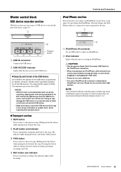
...data on ." Please do not use a USB hub. • The unit's iPod/iPhone IN connector is dedicated to and recognized by Yamaha. (However, Yamaha cannot guarantee operation for the USB device is connected to iPod/iPhone use only. Master control block USB device recorder section With this section ... or upside down this button while playing back rewinds the song. r PLAY button and indicator Press to alternately start /stop recording. MGP32X/MGP24X Owner's Manual 15 The maximum size of the song. ert y Transport section q USB IN connector Connects the USB device. Holding down .
...data on ." Please do not use a USB hub. • The unit's iPod/iPhone IN connector is dedicated to and recognized by Yamaha. (However, Yamaha cannot guarantee operation for the USB device is connected to iPod/iPhone use only. Master control block USB device recorder section With this section ... or upside down this button while playing back rewinds the song. r PLAY button and indicator Press to alternately start /stop recording. MGP32X/MGP24X Owner's Manual 15 The maximum size of the song. ert y Transport section q USB IN connector Connects the USB device. Holding down .
Owner's Manual
Page 16
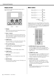
... "0" position corresponds to the STEREO OUT L/R jacks or the GROUP OUT 1 and 2 jacks, respectively. Controls and Connectors Display section This section is on. 16 MGP32X/MGP24X Owner's Manual w STEREO level meter Shows the signal level output to the standard level. Use these meters can be monitored through the MONITOR OUT jacks and...
... "0" position corresponds to the STEREO OUT L/R jacks or the GROUP OUT 1 and 2 jacks, respectively. Controls and Connectors Display section This section is on. 16 MGP32X/MGP24X Owner's Manual w STEREO level meter Shows the signal level output to the standard level. Use these meters can be monitored through the MONITOR OUT jacks and...
Owner's Manual
Page 17
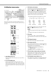
... value will be set (the average of a, b, and c) a b c This section sets the effect returns (FX1 and FX2) on ( ) to GROUP4 buses, and STEREO L/R buses. MGP32X/MGP24X Owner's Manual 17 Rotate this switch on /off, and determines the level of the effect signal and to AUX4 buses. Press the switch in sync with...
... value will be set (the average of a, b, and c) a b c This section sets the effect returns (FX1 and FX2) on ( ) to GROUP4 buses, and STEREO L/R buses. MGP32X/MGP24X Owner's Manual 17 Rotate this switch on /off, and determines the level of the effect signal and to AUX4 buses. Press the switch in sync with...

Owner's Manual
Page 18
... enabled, the AFL indicator does not light, even if the AFL switch is output to the PHONES and MONITOR OUT jacks for monitoring. 18 MGP32X/MGP24X Owner's Manual w STEREO knobs (L, R) These knobs adjust the level of the signals sent from the MATRIX 1 and 2 buses are on monitors the post-AUX1 to AUX6...
... enabled, the AFL indicator does not light, even if the AFL switch is output to the PHONES and MONITOR OUT jacks for monitoring. 18 MGP32X/MGP24X Owner's Manual w STEREO knobs (L, R) These knobs adjust the level of the signals sent from the MATRIX 1 and 2 buses are on monitors the post-AUX1 to AUX6...

Owner's Manual
Page 19
... the connected iPod/iPhone. • TO STEREO ( ): Sends to the STEREO L/R bus. • TO MONITOR ( ): Sends to the MONITOR OUT jacks and PHONES jack. MGP32X/MGP24X Owner's Manual 19 USB IN/iPod IN section Controls and Connectors PHONES/MONITOR section This section determines the destination of headphones and adjust the output signal...
... the connected iPod/iPhone. • TO STEREO ( ): Sends to the STEREO L/R bus. • TO MONITOR ( ): Sends to the MONITOR OUT jacks and PHONES jack. MGP32X/MGP24X Owner's Manual 19 USB IN/iPod IN section Controls and Connectors PHONES/MONITOR section This section determines the destination of headphones and adjust the output signal...
Owner's Manual
Page 20
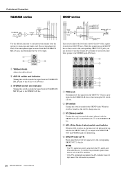
While the signal from each GROUP bus is pressed. 20 MGP32X/MGP24X Owner's Manual To monitor the post-fader signal, make sure to turn off all PFL switches. • If the PFL (preferred) is enabled, the AFL indicator does ...
While the signal from each GROUP bus is pressed. 20 MGP32X/MGP24X Owner's Manual To monitor the post-fader signal, make sure to turn off all PFL switches. • If the PFL (preferred) is enabled, the AFL indicator does ...

