
Owner's Manual
Page 3
... 6 Main features 6 Setup 7 Preparing the power supply 7 Connections 7 Powering up the system 7 Getting sound to the speakers 7 Setup example 8 Controls and Connectors 10 Top panel 10 Rear panel 10 Channel control block 11 Mono input section 11 Stereo input section 11 Master control block 15 USB device recorder section 15 iPod/iPhone section 15 Display section 16 Meter section 16 FX RTN (effect return) section 17 SEND MASTER section 18 MATRIX section 18 USB IN/iPod IN section 19 PHONES/MONITOR section...
... 6 Main features 6 Setup 7 Preparing the power supply 7 Connections 7 Powering up the system 7 Getting sound to the speakers 7 Setup example 8 Controls and Connectors 10 Top panel 10 Rear panel 10 Channel control block 11 Mono input section 11 Stereo input section 11 Master control block 15 USB device recorder section 15 iPod/iPhone section 15 Display section 16 Meter section 16 FX RTN (effect return) section 17 SEND MASTER section 18 MATRIX section 18 USB IN/iPod IN section 19 PHONES/MONITOR section...
Owner's Manual
Page 4
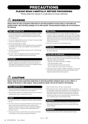
... by Yamaha service personnel. - CAUTION Always follow the basic precautions listed below to unplug the power cord from electrical shock, short-circuiting, damages, fire or other property. These precautions include, but are not using is turned off the power for all connected cables. • When setting up the device, make sure to avoid the possibility of the device. • Use only the supplied power cord/plug...
... by Yamaha service personnel. - CAUTION Always follow the basic precautions listed below to unplug the power cord from electrical shock, short-circuiting, damages, fire or other property. These precautions include, but are not using is turned off the power for all connected cables. • When setting up the device, make sure to avoid the possibility of the device. • Use only the supplied power cord/plug...
Owner's Manual
Page 5
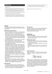
... as in direct sunlight, near a heater, or in a car during the day) to prevent the possibility of the commercially available musical data including but not limited to the faders. Information About copyrights • Copying of panel disfiguration, damage to the internal components or unstable operation. • Do not place vinyl, plastic or rubber objects on the power amplifier LAST...
... as in direct sunlight, near a heater, or in a car during the day) to prevent the possibility of the commercially available musical data including but not limited to the faders. Information About copyrights • Copying of panel disfiguration, damage to the internal components or unstable operation. • Do not place vinyl, plastic or rubber objects on the power amplifier LAST...
Owner's Manual
Page 6
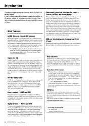
... iPad. USB device recorder A USB device recorder is enclosed in high-end audio devices, and reproduces low frequencies with exceptionally musical characteristics as well as reverb, delay, and modulation effects, along with a graphic equalizer (GEQ) that applies only to enhance the original sound. Convenient, practical functions for the stereo input channels: Ducker, Leveler and Stereo Image. Stereo master - Furthermore, the cutoff frequency can be adjusted, enhancing use of the mixing console for the...
... iPad. USB device recorder A USB device recorder is enclosed in high-end audio devices, and reproduces low frequencies with exceptionally musical characteristics as well as reverb, delay, and modulation effects, along with a graphic equalizer (GEQ) that applies only to enhance the original sound. Convenient, practical functions for the stereo input channels: Ducker, Leveler and Stereo Image. Stereo master - Furthermore, the cutoff frequency can be adjusted, enhancing use of the mixing console for the...
Owner's Manual
Page 7
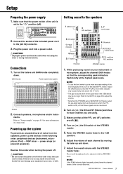
... sure that the PFL/AFL level meter indicator only occasionally rises above the "0" level. • The gain (volume) level of the STEREO master. 5. Adjust the GAIN knobs so that the power switch of each channel you use the level meter to turn on connections. Adjust the volume of the unit is adjusted with the STEREO master fader. MGP32X/MGP24X Owner's Manual 7 ments. Setup Preparing the power supply 1. CAUTION • Unplug the power cord from the speakers, power up and down . Connect speakers, microphones and/or instru- Getting...
... sure that the PFL/AFL level meter indicator only occasionally rises above the "0" level. • The gain (volume) level of the STEREO master. 5. Adjust the GAIN knobs so that the power switch of each channel you use the level meter to turn on connections. Adjust the volume of the unit is adjusted with the STEREO master fader. MGP32X/MGP24X Owner's Manual 7 ments. Setup Preparing the power supply 1. CAUTION • Unplug the power cord from the speakers, power up and down . Connect speakers, microphones and/or instru- Getting...

Owner's Manual
Page 10
... 16) SEND MASTER section (page 18) MATRIX section (page 18) USB IN/iPod IN section (page 19) PHONES/MONITOR section (page 19) TALKBACK section (page 20) Rear panel STEREO master section (page 21) MONO master section (page 21) GROUP section (page 20) FX RTN (effect return) section (page 17) Channel I/O connectors section (page 22) Master I/O connectors section (page 22) Power section (page 23) 10 MGP32X/MGP24X Owner's Manual
... 16) SEND MASTER section (page 18) MATRIX section (page 18) USB IN/iPod IN section (page 19) PHONES/MONITOR section (page 19) TALKBACK section (page 20) Rear panel STEREO master section (page 21) MONO master section (page 21) GROUP section (page 20) FX RTN (effect return) section (page 17) Channel I/O connectors section (page 22) Master I/O connectors section (page 22) Power section (page 23) 10 MGP32X/MGP24X Owner's Manual
Owner's Manual
Page 11
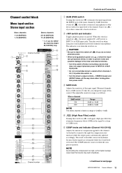
... noise and possible damage to the mixer and external devices. • Turn this switch off . e GAIN knob Adjusts the sensitivity of XLR input jacks. w +48V switch and indicator Toggles phantom power on ( ) attenuates the input signal from channels 124 {1-16} while this switch is fixed to INPUT A of the input signal. The indicator is on ( ), the mixer supplies DC +48V power to a range of the mono channel by a slope of XLR input jacks • Do not connect...
... noise and possible damage to the mixer and external devices. • Turn this switch off . e GAIN knob Adjusts the sensitivity of XLR input jacks. w +48V switch and indicator Toggles phantom power on ( ) attenuates the input signal from channels 124 {1-16} while this switch is fixed to INPUT A of the input signal. The indicator is on ( ), the mixer supplies DC +48V power to a range of the mono channel by a slope of XLR input jacks • Do not connect...

Owner's Manual
Page 13
... off ( ), the mixer feeds the post-fader signal. !4 FX (effect) knobs (1, 2) These knobs adjust the channel's post-fader signal levels into the AUX bus. NOTE To send the signal to the "t" (nominal) position. On stereo channels, the LINE L (odd) and LINE R (even) input signals are mixed before moving into the FX bus. For AUX5 and AUX6, only the post-fader signal can monitor the channel's pre-fader signal through the PHONES jack even when the ON switch is output to the...
... off ( ), the mixer feeds the post-fader signal. !4 FX (effect) knobs (1, 2) These knobs adjust the channel's post-fader signal levels into the AUX bus. NOTE To send the signal to the "t" (nominal) position. On stereo channels, the LINE L (odd) and LINE R (even) input signals are mixed before moving into the FX bus. For AUX5 and AUX6, only the post-fader signal can monitor the channel's pre-fader signal through the PHONES jack even when the ON switch is output to the...
Owner's Manual
Page 15
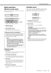
... • While the unit is 2GB. Doing so may cause a notification sound to be output. The indicator lights during recording, playing back, and saving operations), do NOT remove the USB device from the USB IN connector, and do NOT turn off and plugging or unplugging the USB cable. • Please do not connect other USB devices. q iPod/iPhone IN connector Use an USB cable to alternately start /stop recording.
... • While the unit is 2GB. Doing so may cause a notification sound to be output. The indicator lights during recording, playing back, and saving operations), do NOT remove the USB device from the USB IN connector, and do NOT turn off and plugging or unplugging the USB cable. • Please do not connect other USB devices. q iPod/iPhone IN connector Use an USB cable to alternately start /stop recording.
Owner's Manual
Page 16
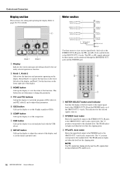
... input channel's PFL switch is for details. u USB button Calls up the display to adjust the contrast of the display, and to the output signal level of the STEREO OUT L/R and the PHONES jacks, or of the functions. Refer to operate the functions on the lower left side of the level meter to set the ducker and the leveler. Meter section Knob 1 Knob 2 q Display Indicates the various messages and settings related to record and play...
... input channel's PFL switch is for details. u USB button Calls up the display to adjust the contrast of the display, and to the output signal level of the STEREO OUT L/R and the PHONES jacks, or of the functions. Refer to operate the functions on the lower left side of the level meter to set the ducker and the leveler. Meter section Knob 1 Knob 2 q Display Indicates the various messages and settings related to record and play...
Owner's Manual
Page 22
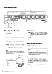
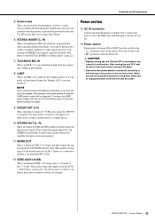
... phone output jacks that connect linelevel instruments, such as illustrated below. Controls and Connectors Rear input/output block Channel I/O connectors section CH25/26-31/32 {CH17/18-23/24} CH1-24 {CH1-16} Master I/O connectors section Power section Channel I /O connectors section e MATRIX OUT (1, 2) These are impedance-balanced (*) TRS phone jacks. Use a separately-sold Yamaha insertion cable (YIC025/050/070). NOTE Connection to devices such as graphic equalizers, compressors, and noise filters...
... phone output jacks that connect linelevel instruments, such as illustrated below. Controls and Connectors Rear input/output block Channel I/O connectors section CH25/26-31/32 {CH17/18-23/24} CH1-24 {CH1-16} Master I/O connectors section Power section Channel I /O connectors section e MATRIX OUT (1, 2) These are impedance-balanced (*) TRS phone jacks. Use a separately-sold Yamaha insertion cable (YIC025/050/070). NOTE Connection to devices such as graphic equalizers, compressors, and noise filters...
Owner's Manual
Page 23
... XLR-3-32 output jacks (1: Ground; 2: Hot; 3: Cold). Connect these jacks to connect to the inputs of the mixed stereo bus (L/R). Connect to the power amplifier that outputs the signal adjusted by the user. These jacks output the signals from the wall AC outlet. ring=return/in succession can use these jacks to connect to turn on again. NOTE If you connect a lamp with this product, and must be triggered. This outputs a mono signal of a multi-track recorder, external mixer, or similar...
... XLR-3-32 output jacks (1: Ground; 2: Hot; 3: Cold). Connect these jacks to connect to the inputs of the mixed stereo bus (L/R). Connect to the power amplifier that outputs the signal adjusted by the user. These jacks output the signals from the wall AC outlet. ring=return/in succession can use these jacks to connect to turn on again. NOTE If you connect a lamp with this product, and must be triggered. This outputs a mono signal of a multi-track recorder, external mixer, or similar...
Owner's Manual
Page 24
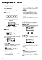
... HOME button. Example: WARNING screen • MESSAGE This screen appears when the operation is not executed because the conditions are not right, or when user memory is initialized. • WARNING This screen appears when an inappropriate device is connected to display the desired screen. Example: Screen when pressing the COMP button Page number Screen name Page name Function (Knob 1) Parameter setting area Function (Knob 2) e USB status Displays the inserted (highlighted...
... HOME button. Example: WARNING screen • MESSAGE This screen appears when the operation is not executed because the conditions are not right, or when user memory is initialized. • WARNING This screen appears when an inappropriate device is connected to display the desired screen. Example: Screen when pressing the COMP button Page number Screen name Page name Function (Knob 1) Parameter setting area Function (Knob 2) e USB status Displays the inserted (highlighted...
Owner's Manual
Page 26
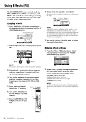
... FX2 screens are displayed on the ON switch of 16 types, including reverb, delay, echo). play repeatedly if necessary until the (1/ 2) MAIN page appears. Turn on . 9. FX1 2. Rotate Knob 2 to the "0" position. Raise the input channel fader to adjust the effect depth. Using Effects (FX) The MGP32X/MGP24X features two built-in finer units of the input channel, and then rotate the channel's FX1 (or FX2) knob to send the signal to adjust...
... FX2 screens are displayed on the ON switch of 16 types, including reverb, delay, echo). play repeatedly if necessary until the (1/ 2) MAIN page appears. Turn on . 9. FX1 2. Rotate Knob 2 to the "0" position. Raise the input channel fader to adjust the effect depth. Using Effects (FX) The MGP32X/MGP24X features two built-in finer units of the input channel, and then rotate the channel's FX1 (or FX2) knob to send the signal to adjust...

Owner's Manual
Page 34
... indicator lights steadily, you to "USB IN" ( ). Connect a USB device containing audio files to can begin recording. 7. back. To output to the STEREO bus Set the TO STEREO/TO MONITOR switch in the USB IN section to "TO MONITOR" ( ). To output to channels 29/30 {21/22} Set the input select switch for channels 29/30 {21/22} at the same time. NOTE AUTO REC function: If you press the FWD button while recording...
... indicator lights steadily, you to "USB IN" ( ). Connect a USB device containing audio files to can begin recording. 7. back. To output to the STEREO bus Set the TO STEREO/TO MONITOR switch in the USB IN section to "TO MONITOR" ( ). To output to channels 29/30 {21/22} Set the input select switch for channels 29/30 {21/22} at the same time. NOTE AUTO REC function: If you press the FWD button while recording...
Owner's Manual
Page 36
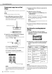
... connected to stop the song. iPod/iPhone IN connector Lit 2. Specify the output assignment for playback. To output to the STEREO bus Set the TO STEREO/TO MONITOR switch in the iPod IN section to "TO MONITOR" ( ). To output to channels 31/32 {23/24} Set the input select switch for recording formats such as MP3:128k, MP3:192k, or MP3:256k. NOTE Avoid adjusting both the STEREO/MONITOR level control (USB...
... connected to stop the song. iPod/iPhone IN connector Lit 2. Specify the output assignment for playback. To output to the STEREO bus Set the TO STEREO/TO MONITOR switch in the iPod IN section to "TO MONITOR" ( ). To output to channels 31/32 {23/24} Set the input select switch for recording formats such as MP3:128k, MP3:192k, or MP3:256k. NOTE Avoid adjusting both the STEREO/MONITOR level control (USB...
Owner's Manual
Page 40
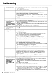
.../24} jacks Sound is faint, distorted, or noisy. No effect is turned on. Are microphones, external devices, and speakers connected correctly? Is a Y-shaped cable used to connect the INSERT connector or an external device? Are your cables connected properly, or are they shorted or faulty? Are the channel GAIN knobs, channel faders, STEREO master fader and GROUP faders set to appropriate levels? Are the bus assign switch and switches in the USB IN section...
.../24} jacks Sound is faint, distorted, or noisy. No effect is turned on. Are microphones, external devices, and speakers connected correctly? Is a Y-shaped cable used to connect the INSERT connector or an external device? Are your cables connected properly, or are they shorted or faulty? Are the channel GAIN knobs, channel faders, STEREO master fader and GROUP faders set to appropriate levels? Are the bus assign switch and switches in the USB IN section...
Owner's Manual
Page 41
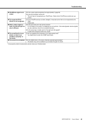
... the GAIN knob on the stereo channels adjusted appropriately? A cable with resistance lowers the volume. Are you increase the gain too much. * If any specific problem should persist, please contact your Yamaha dealer. Troubleshooting iPod/iPhone signal is not output. The supported iPod/ iPhone is not recognized. When a stereo signal is input, the left signals? Check which iPod/iPhone models are also switched, check the connected device...
... the GAIN knob on the stereo channels adjusted appropriately? A cable with resistance lowers the volume. Are you increase the gain too much. * If any specific problem should persist, please contact your Yamaha dealer. Troubleshooting iPod/iPhone signal is not output. The supported iPod/ iPhone is not recognized. When a stereo signal is input, the left signals? Check which iPod/iPhone models are also switched, check the connected device...
Owner's Manual
Page 48
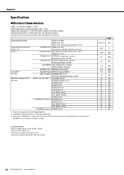
... Hz to 20 kHz GAIN knob: min Refer to the nominal output level @1 kHz STEREO OUT GAIN knob: min output level: +14 dBu @20 Hz to 20 kHz CH INPUT MIC EIN (Equivalent Input Noise): Rs = 150 Ω GAIN knob: max STEREO OUT STEREO master fader: nominal Bus assign switch: off (All) GROUP OUT GROUP master fader: nominal Bus assign switch: off (All) AUX SEND AUX master knob: nominal CH mix control: min (All) STEREO OUT Residual output noise Adjacent Input Between input channels Input to Output STEREO OUT L, R PAN knob...
... Hz to 20 kHz GAIN knob: min Refer to the nominal output level @1 kHz STEREO OUT GAIN knob: min output level: +14 dBu @20 Hz to 20 kHz CH INPUT MIC EIN (Equivalent Input Noise): Rs = 150 Ω GAIN knob: max STEREO OUT STEREO master fader: nominal Bus assign switch: off (All) GROUP OUT GROUP master fader: nominal Bus assign switch: off (All) AUX SEND AUX master knob: nominal CH mix control: min (All) STEREO OUT Residual output noise Adjacent Input Between input channels Input to Output STEREO OUT L, R PAN knob...
Owner's Manual
Page 55
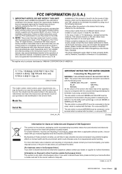
... or fuse) circuits or install AC line filter/s. Compliance with this mains lead are on human health and the environment which is marked by the letter E or by YAMAHA CORPORATION OF AMERICA. In the case of this manual as indicated in the instructions contained in this product in other electronic devices. If you wish to eliminate the problem by using...
... or fuse) circuits or install AC line filter/s. Compliance with this mains lead are on human health and the environment which is marked by the letter E or by YAMAHA CORPORATION OF AMERICA. In the case of this manual as indicated in the instructions contained in this product in other electronic devices. If you wish to eliminate the problem by using...


