Owner's Manual
Page 2
... lead, change the lead-in FCC Regulations, Part 15 for Class "B" digital devices. If the antenna lead-in is being affected by Yamaha-Kemble Music (U.K.) Ltd. (2 wires) FCC INFORMATION (U.S.A.) 1. Failure to use of this product in a residential environment will not occur in the users manual, may cause interference harmful to the terminal which is found in all installation instructions. If...
... lead, change the lead-in FCC Regulations, Part 15 for Class "B" digital devices. If the antenna lead-in is being affected by Yamaha-Kemble Music (U.K.) Ltd. (2 wires) FCC INFORMATION (U.S.A.) 1. Failure to use of this product in a residential environment will not occur in the users manual, may cause interference harmful to the terminal which is found in all installation instructions. If...
Owner's Manual
Page 3
... : Power supply/Power cord • Remove the electric plug from electrical shock, short-circuiting, damages, fire or other hazards. Pulling by qualified Yamaha service personnel. Even when the power switch is turned off the power switch, disconnect the electric plug from the outlet, and have it , immediately turn off , electricity is still flowing to the product all connected cables. • When setting up...
... : Power supply/Power cord • Remove the electric plug from electrical shock, short-circuiting, damages, fire or other hazards. Pulling by qualified Yamaha service personnel. Even when the power switch is turned off the power switch, disconnect the electric plug from the outlet, and have it , immediately turn off , electricity is still flowing to the product all connected cables. • When setting up...
Owner's Manual
Page 4
...: sleeve: ground, tip: send, and ring: return. Please respect all volume levels to the device, or data that the panel temperature may not match actual appearance during operation. * Company names and product names herein are not using the device for information purposes only. The main differences between the three models are the number of input channels and whether the internal effects are wired as...
...: sleeve: ground, tip: send, and ring: return. Please respect all volume levels to the device, or data that the panel temperature may not match actual appearance during operation. * Company names and product names herein are not using the device for information purposes only. The main differences between the three models are the number of input channels and whether the internal effects are wired as...
Owner's Manual
Page 5
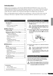
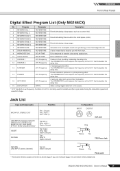
... Modulation Effects: Phasing, Chorus, and Flanging 10 Compression 10 ■ Reference 11 Setup 11 Front & Rear Panels 12 Channel Control Section 12 Digital Effects 15 Master Control Section 16 Digital Effect Program List (Only MG166CX).19 Jack List 19 Troubleshooting 20 Specifications 75 Accessories • Owner's Manual • AC power adaptor (PA-30)* * May not be sure to secure the connection. Contents Introduction 5 Contents 5 Before Turning on the rear of operation with your particular area. The MG206C...
... Modulation Effects: Phasing, Chorus, and Flanging 10 Compression 10 ■ Reference 11 Setup 11 Front & Rear Panels 12 Channel Control Section 12 Digital Effects 15 Master Control Section 16 Digital Effect Program List (Only MG166CX).19 Jack List 19 Troubleshooting 20 Specifications 75 Accessories • Owner's Manual • AC power adaptor (PA-30)* * May not be sure to secure the connection. Contents Introduction 5 Contents 5 Before Turning on the rear of operation with your particular area. The MG206C...
Owner's Manual
Page 6
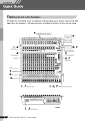
Mixer Basics Quick Guide Mixer Basics Getting Sound to the input devices you are using. 1, 4 GAIN controls 4 PEAK indicators Equalizer 2 Microphones, instruments 2 Speakers Power Amp 2, 4 Headphones Monitor Speakers 3 PHANTOM switch 4, 7 Level meter PAN/BAL switches 5 ON switches 4 PFL switches 5 ST switches 1, 7 Channel faders 1, 6, 7 STEREO OUT Master fader 1, 3 POWER switch 6 MG206C/MG166CX/MG166C Owner's Manual MG206C Note that operations and procedures will vary somewhat according to the Speakers We begin by connecting a pair of speakers and generating some stereo output.
Mixer Basics Quick Guide Mixer Basics Getting Sound to the input devices you are using. 1, 4 GAIN controls 4 PEAK indicators Equalizer 2 Microphones, instruments 2 Speakers Power Amp 2, 4 Headphones Monitor Speakers 3 PHANTOM switch 4, 7 Level meter PAN/BAL switches 5 ON switches 4 PFL switches 5 ST switches 1, 7 Channel faders 1, 6, 7 STEREO OUT Master fader 1, 3 POWER switch 6 MG206C/MG166CX/MG166C Owner's Manual MG206C Note that operations and procedures will vary somewhat according to the Speakers We begin by connecting a pair of speakers and generating some stereo output.
Owner's Manual
Page 7
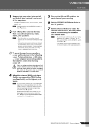
... directly to the MG mixer may result in the following order: Peripheral devices → MG mixer → power amps (or powered speakers). NOTE To use the level meter to view the level being applied to the STEREO L/R buses, set the PFL switch off ( ) and the MONITOR switch to STEREO ( ). • If the PEAK indicator lights frequently, lower the Channel faders a little to their ▼ positions. 2 Turn off any other external devices, then connect microphones...
... directly to the MG mixer may result in the following order: Peripheral devices → MG mixer → power amps (or powered speakers). NOTE To use the level meter to view the level being applied to the STEREO L/R buses, set the PFL switch off ( ) and the MONITOR switch to STEREO ( ). • If the PEAK indicator lights frequently, lower the Channel faders a little to their ▼ positions. 2 Turn off any other external devices, then connect microphones...
Owner's Manual
Page 8
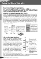
... performance and make better mixes. Short linelevel runs Unbalanced lines are almost always used a mixer you go ... Balanced noise cancellation Noise Phase inversion Hot (+) Cold (-) Ground Source Cable Phase inversion Noise cancelled Receiving device Noise-free signal To summarize Microphones Use balanced lines. Mixer Basics Making the Most of Your Mixer You've got yourself a mixer and now you're ready to use audio gear usually have a nominal level of -7.8 dBu (-10...
... performance and make better mixes. Short linelevel runs Unbalanced lines are almost always used a mixer you go ... Balanced noise cancellation Noise Phase inversion Hot (+) Cold (-) Ground Source Cable Phase inversion Noise cancelled Receiving device Noise-free signal To summarize Microphones Use balanced lines. Mixer Basics Making the Most of Your Mixer You've got yourself a mixer and now you're ready to use audio gear usually have a nominal level of -7.8 dBu (-10...
Owner's Manual
Page 10
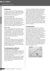
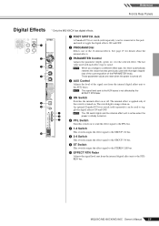
Reverb Level It's amazing how quickly your ears can lose perspective and fool you . For phasing effects the shift is set properly to achieve the desired sound. Most compressors require several milliseconds, with the delay time modulated by several critical parameters to be adjusted to create a wide variety of "grooves". Delay times can be set a single "compression" control and all of the pertinent parameters are automatically...
Reverb Level It's amazing how quickly your ears can lose perspective and fool you . For phasing effects the shift is set properly to achieve the desired sound. Most compressors require several milliseconds, with the delay time modulated by several critical parameters to be adjusted to create a wide variety of "grooves". Delay times can be set a single "compression" control and all of the pertinent parameters are automatically...
Owner's Manual
Page 13
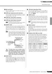
... channels that provide multiple input jack options only one type of jack can be used at a time. 5 INSERT Jacks These jacks can be used to insert an external signal-processing device between the S/N ratio and the dynamic range, adjust the gain so that the PEAK indicator 9 lights only occasionally and briefly on or off. sleeve = ground). This should not be a problem when connecting to the line inputs of stereo input channels 3, 4). 8 COMP Control Adjusts...
... channels that provide multiple input jack options only one type of jack can be used at a time. 5 INSERT Jacks These jacks can be used to insert an external signal-processing device between the S/N ratio and the dynamic range, adjust the gain so that the PEAK indicator 9 lights only occasionally and briefly on or off. sleeve = ground). This should not be a problem when connecting to the line inputs of stereo input channels 3, 4). 8 COMP Control Adjusts...
Owner's Manual
Page 14
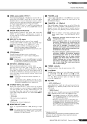
... & Rear Panels A AUX, EFFECT Control Adjusts the level of the channel signal. B AUX PRE Switch Selects whether the pre-fader or the post-fader signal is fed to the AUX buses. If the switch is on ( ), the mixer sends the pre-fader signal to the AUX buses, so that it lights to the GROUP 1/2 bus turn it on ( ). signals input to the R input (even channel) go to the GROUP 1 or 3 buses or to the GROUP 3/4 bus turn the ON switch on ( ). E PFL (Pre-Fader Listen) Switch This switch lets you monitor the channel's pre-fader signal...
... & Rear Panels A AUX, EFFECT Control Adjusts the level of the channel signal. B AUX PRE Switch Selects whether the pre-fader or the post-fader signal is fed to the AUX buses. If the switch is on ( ), the mixer sends the pre-fader signal to the AUX buses, so that it lights to the GROUP 1/2 bus turn it on ( ). signals input to the R input (even channel) go to the GROUP 1 or 3 buses or to the GROUP 3/4 bus turn the ON switch on ( ). E PFL (Pre-Fader Listen) Switch This switch lets you monitor the channel's pre-fader signal...
Owner's Manual
Page 15
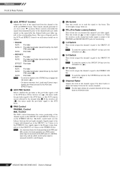
... used to toggle the digital effects ON and OFF. 7 NOTE The ON switch lights and the internal effect unit is active when the 8 power is not affected by the EFFECT RTN fader. 5 ON Switch Switches the internal effect on or off . 4 AUX Control Adjusts the level of the PARAMETER knob). The switch lights orange when on to send the effect signal to the PFL bus. 7 1-2 Switch This switch assigns the effect signal to the GROUP 1/2 bus. 8 3-4 Switch This switch assigns the effect signal to the GROUP 3/4 bus. 9 ST Switch...
... used to toggle the digital effects ON and OFF. 7 NOTE The ON switch lights and the internal effect unit is active when the 8 power is not affected by the EFFECT RTN fader. 5 ON Switch Switches the internal effect on or off . 4 AUX Control Adjusts the level of the PARAMETER knob). The switch lights orange when on to send the effect signal to the PFL bus. 7 1-2 Switch This switch assigns the effect signal to the GROUP 1/2 bus. 8 3-4 Switch This switch assigns the effect signal to the GROUP 3/4 bus. 9 ST Switch...
Owner's Manual
Page 17
... STEREO L/R bus as well as an MD recorder in the Master Control section. 5 RETURN L (MONO), R Jacks These are connecting to a monitor system, while the post-fader send option is on the mixer supplies +48V phantom power to all output controls (STEREO OUT Master fader, GROUP 1-2 fader, GROUP 3-4 fader, etc.) to their minimum settings before turning this switch off if you want to send the signal using the 2TR IN switch, and adjust the signal level using the RETURN1 AUX1, AUX2 and the STEREO controls, and signals input via these jacks...
... STEREO L/R bus as well as an MD recorder in the Master Control section. 5 RETURN L (MONO), R Jacks These are connecting to a monitor system, while the post-fader send option is on the mixer supplies +48V phantom power to all output controls (STEREO OUT Master fader, GROUP 1-2 fader, GROUP 3-4 fader, etc.) to their minimum settings before turning this switch off if you want to send the signal using the 2TR IN switch, and adjust the signal level using the RETURN1 AUX1, AUX2 and the STEREO controls, and signals input via these jacks...
Owner's Manual
Page 18
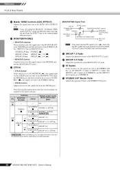
... bus MONITOR/PHONES controls MONITOR OUT/PHONES jacks signal STEREO OUT Master fader REC OUT jacks NOTE If the input channel PFL switch is set to TO STEREO ( ), the signals are using the MG166CX, the Master SEND control (EFFECT) does not affect the level of the signal output to the internal digital effect processor. G GROUP 3-4 Fader Adjust the signal level to the STEREO OUT jacks. 18 MG206C/MG166CX/MG166C Owner's Manual D MONITOR/PHONES • MONITOR switches These switches select the signal sent to the MONITOR OUT jacks, the PHONES jack, and the level meter. H ST Switch...
... bus MONITOR/PHONES controls MONITOR OUT/PHONES jacks signal STEREO OUT Master fader REC OUT jacks NOTE If the input channel PFL switch is set to TO STEREO ( ), the signals are using the MG166CX, the Master SEND control (EFFECT) does not affect the level of the signal output to the internal digital effect processor. G GROUP 3-4 Fader Adjust the signal level to the STEREO OUT jacks. 18 MG206C/MG166CX/MG166C Owner's Manual D MONITOR/PHONES • MONITOR switches These switches select the signal sent to the MONITOR OUT jacks, the PHONES jack, and the level meter. H ST Switch...
Owner's Manual
Page 19
... the delay time. The PARAMETER control adjusts the frequency of the LFO* that modulates the delay time. The PARAMETER control adjusts the frequency of the LFO* that modulates the delay time. A short reverb that modulates the delay time. Jack List Input and Output Jacks Polarities MIC INPUT, STEREO OUT Pin 1: Ground Pin 2: Hot (+) Pin 3: Cold (-) LINE INPUT (monaural channels) GROUP OUT, STEREO OUT, MONITOR OUT, AUX SEND, EFFECT SEND (Only MG166CX)* INSERT PHONES Tip: Hot (+) Ring: Cold (-) Sleeve: Ground Tip: Output Ring: Input Sleeve...
... the delay time. The PARAMETER control adjusts the frequency of the LFO* that modulates the delay time. The PARAMETER control adjusts the frequency of the LFO* that modulates the delay time. A short reverb that modulates the delay time. Jack List Input and Output Jacks Polarities MIC INPUT, STEREO OUT Pin 1: Ground Pin 2: Hot (+) Pin 3: Cold (-) LINE INPUT (monaural channels) GROUP OUT, STEREO OUT, MONITOR OUT, AUX SEND, EFFECT SEND (Only MG166CX)* INSERT PHONES Tip: Hot (+) Ring: Cold (-) Sleeve: Ground Tip: Output Ring: Input Sleeve...
Owner's Manual
Page 20
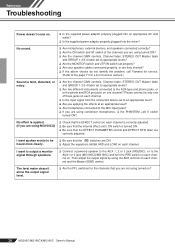
... output a monitor signal through speakers. ❑ Connect a powered speaker to the AUX 1, 2 or 3 jack (MG206C), or to the AUX1 or 2 jack (MG166CX/MG166C) and turn the PRE switch on each channel on each channel is correctly adjusted. ❑ Be sure that the EFFECT control on . Then adjust the output signal by using MG166CX) ❑ Check that the internal effect unit's ON switch is faint, distorted, or noisy. ❑ Are the channel GAIN controls, Channel fader, STEREO OUT Master fader and GROUP 1-2/3-4 fader set properly? ❑ Are your speaker cables connected...
... output a monitor signal through speakers. ❑ Connect a powered speaker to the AUX 1, 2 or 3 jack (MG206C), or to the AUX1 or 2 jack (MG166CX/MG166C) and turn the PRE switch on each channel on each channel is correctly adjusted. ❑ Be sure that the EFFECT control on . Then adjust the output signal by using MG166CX) ❑ Check that the internal effect unit's ON switch is faint, distorted, or noisy. ❑ Are the channel GAIN controls, Channel fader, STEREO OUT Master fader and GROUP 1-2/3-4 fader set properly? ❑ Are your speaker cables connected...
Owner's Manual
Page 21
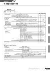
... Input Noise): Rs = 150 Ω, GAIN: maximum STEREO OUT STEREO OUT, GROUP 1-2 fader and GROUP 3-4 fader at GROUP OUT nominal level and all CH AUX controls at nominal level. STEREO OUT STEREO OUT, GROUP 1-2, GROUP 3-4 faders and one CH GROUP OUT fader at minimum. Pre MONITOR Level 2x12 points LED meter (PEAK, +10, +6, +3, 0, -3, -6, -10, -15, -20, -25, -30 dB) STEREO/GROUP/PFL bus PEAK lights if the signal level reaches 3 dB below clipping (+17 dBu). PA-30 AC 35 VCT, 1.4 A, Cable Length...
... Input Noise): Rs = 150 Ω, GAIN: maximum STEREO OUT STEREO OUT, GROUP 1-2 fader and GROUP 3-4 fader at GROUP OUT nominal level and all CH AUX controls at nominal level. STEREO OUT STEREO OUT, GROUP 1-2, GROUP 3-4 faders and one CH GROUP OUT fader at minimum. Pre MONITOR Level 2x12 points LED meter (PEAK, +10, +6, +3, 0, -3, -6, -10, -15, -20, -25, -30 dB) STEREO/GROUP/PFL bus PEAK lights if the signal level reaches 3 dB below clipping (+17 dBu). PA-30 AC 35 VCT, 1.4 A, Cable Length...
Owner's Manual
Page 22
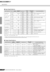
... output level when the unit is set to the maximum level. (All faders and level controls are at their maximum position.) ■ Output Specifications Output Connectors Output Impedance Appropriate Impedance STEREO OUT (L, R) 75Ω 600Ω Lines GROUP OUT (1-4) 150Ω 10kΩ Lines AUX SEND (1-4) 150Ω 10kΩ Lines CH INSERT OUT (CHs 1-12) REC OUT (L, R) 75Ω 600Ω 10kΩ Lines 10kΩ Lines MONITOR...
... output level when the unit is set to the maximum level. (All faders and level controls are at their maximum position.) ■ Output Specifications Output Connectors Output Impedance Appropriate Impedance STEREO OUT (L, R) 75Ω 600Ω Lines GROUP OUT (1-4) 150Ω 10kΩ Lines AUX SEND (1-4) 150Ω 10kΩ Lines CH INSERT OUT (CHs 1-12) REC OUT (L, R) 75Ω 600Ω 10kΩ Lines 10kΩ Lines MONITOR...
Owner's Manual
Page 23
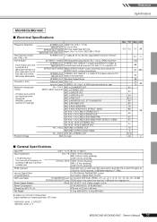
... Owner's Manual 77 Output impedance of shelving: 3 dB blow maximum variable level. equivalent to 15/16, RETURN, 2TR IN MONITOR OUT, REC OUT STEREO OUT +14 dBu @ 20 Hz-20 kHz, Input GAIN Control at minimum CH INPUT 1-8 MIC EIN (Equivalent Input Noise): Rs = 150 Ω, GAIN: maximum STEREO OUT STEREO OUT, GROUP 1-2 fader and GROUP 3-4 fader at GROUP OUT nominal level and all CH EFFECT/AUX* controls at minimum. PEAK Indicator Internal Digital Effect (Only MG166CX) LED Level Meter Power Supply...
... Owner's Manual 77 Output impedance of shelving: 3 dB blow maximum variable level. equivalent to 15/16, RETURN, 2TR IN MONITOR OUT, REC OUT STEREO OUT +14 dBu @ 20 Hz-20 kHz, Input GAIN Control at minimum CH INPUT 1-8 MIC EIN (Equivalent Input Noise): Rs = 150 Ω, GAIN: maximum STEREO OUT STEREO OUT, GROUP 1-2 fader and GROUP 3-4 fader at GROUP OUT nominal level and all CH EFFECT/AUX* controls at minimum. PEAK Indicator Internal Digital Effect (Only MG166CX) LED Level Meter Power Supply...
Owner's Manual
Page 24
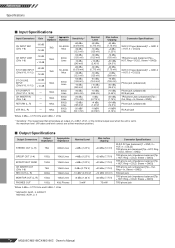
... nominal output level when the unit is set to the maximum level. (All faders and level controls are at their maximum position.) ■ Output Specifications Output Connectors Output Impedance Appropriate Impedance STEREO OUT (L, R) 75Ω 600Ω Lines GROUP OUT (1-4) 150Ω 10kΩ Lines EFFECT/AUX* SEND 150Ω 10kΩ Lines CH INSERT OUT (CHs 1-8) REC OUT (L, R) 75Ω 600Ω 10kΩ Lines 10kΩ Lines MONITOR...
... nominal output level when the unit is set to the maximum level. (All faders and level controls are at their maximum position.) ■ Output Specifications Output Connectors Output Impedance Appropriate Impedance STEREO OUT (L, R) 75Ω 600Ω Lines GROUP OUT (1-4) 150Ω 10kΩ Lines EFFECT/AUX* SEND 150Ω 10kΩ Lines CH INSERT OUT (CHs 1-8) REC OUT (L, R) 75Ω 600Ω 10kΩ Lines 10kΩ Lines MONITOR...
Owner's Manual
Page 27
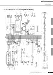
... LED Meter MONI/PHONES INV [-16dBu] INV SUM SUM SUM AUX SEND 1 [0dBu] [-6dBu] BA AUX SEND 2 [0dBu] [-6dBu] BA [0dBu] AUX SEND* [-6dBu] BA MONITOR MIX MODEL MG166C MG166CX AUX * AUX 3 EFFECT 1 2 GROUP OUT [+4dBu] 3 4 L STEREO OUT [+4dBu] R L REC OUT [-10dBV] R [-7.8dBu] L MONITOR OUT [+4dBu] R PHONES [3mW,40ohms] AUX SEND 1 [+4dBu] AUX SEND 2 [+4dBu] AUX SEND * [+4dBu] [-6dBu] Clip Level Clip Level Clip Level Clip Level AUX SEND *1 [+4dBu] GROUP OUT [+4dBu] AUX SEND *1 [Nominal:-6dB] GROUP Fader [Nominal:-10dB] ST Master [Nominal...
... LED Meter MONI/PHONES INV [-16dBu] INV SUM SUM SUM AUX SEND 1 [0dBu] [-6dBu] BA AUX SEND 2 [0dBu] [-6dBu] BA [0dBu] AUX SEND* [-6dBu] BA MONITOR MIX MODEL MG166C MG166CX AUX * AUX 3 EFFECT 1 2 GROUP OUT [+4dBu] 3 4 L STEREO OUT [+4dBu] R L REC OUT [-10dBV] R [-7.8dBu] L MONITOR OUT [+4dBu] R PHONES [3mW,40ohms] AUX SEND 1 [+4dBu] AUX SEND 2 [+4dBu] AUX SEND * [+4dBu] [-6dBu] Clip Level Clip Level Clip Level Clip Level AUX SEND *1 [+4dBu] GROUP OUT [+4dBu] AUX SEND *1 [Nominal:-6dB] GROUP Fader [Nominal:-10dB] ST Master [Nominal...


