
Owner's Manual
Page 3
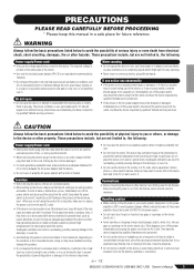
... an equivalent recommended by qualified Yamaha service personnel. • Do not use of time, or during use the device or headphones for a long time, make sure that it , immediately turn on or off the power for all devices, set all the minimum level. This device has ventilation holes at a high or uncomfortable volume level, since this can result in overheating, possibly...
... an equivalent recommended by qualified Yamaha service personnel. • Do not use of time, or during use the device or headphones for a long time, make sure that it , immediately turn on or off the power for all devices, set all the minimum level. This device has ventilation holes at a high or uncomfortable volume level, since this can result in overheating, possibly...
Owner's Manual
Page 4
... somewhat different from the wall AC outlet. The main differences between the three models are the number of copyright has legal consequences. Please respect all computer software, style files, MIDI files, WAVE data, musical scores and sound recordings. The illustrations and LCD screens as switches, volume controls, and connectors, deteriorates over time. Always turn the power off when the device is not in this...
... somewhat different from the wall AC outlet. The main differences between the three models are the number of copyright has legal consequences. Please respect all computer software, style files, MIDI files, WAVE data, musical scores and sound recordings. The illustrations and LCD screens as switches, volume controls, and connectors, deteriorates over time. Always turn the power off when the device is not in this...
Owner's Manual
Page 5
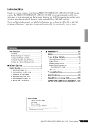
... input channels suitable for a wide range of the Yamaha MG206C-USB/MG166CX-USB/MG166C-USB mixing console. Installing Cubase AI 4 7 2. Powering Up the System 8 4. Recording with Cubase AI 4 13 ■ Reference 15 Setup 15 Front & Rear Panels 16 Channel Control Section 16 Digital Effects 19 Master Control Section 20 Digital Effect Program List (Only MG166CX-USB 23 Jack List 23 Troubleshooting 24 Specifications 99 About the accessory disk 106 SOFTWARE LICENSE AGREEMENT...106 Accessories • Cubase AI 4 DVD-ROM • USB cable • Owner's Manual...
... input channels suitable for a wide range of the Yamaha MG206C-USB/MG166CX-USB/MG166C-USB mixing console. Installing Cubase AI 4 7 2. Powering Up the System 8 4. Recording with Cubase AI 4 13 ■ Reference 15 Setup 15 Front & Rear Panels 16 Channel Control Section 16 Digital Effects 19 Master Control Section 20 Digital Effect Program List (Only MG166CX-USB 23 Jack List 23 Troubleshooting 24 Specifications 99 About the accessory disk 106 SOFTWARE LICENSE AGREEMENT...106 Accessories • Cubase AI 4 DVD-ROM • USB cable • Owner's Manual...
Owner's Manual
Page 7
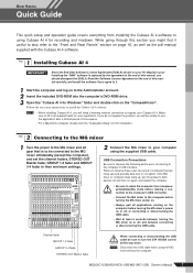
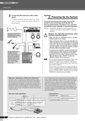
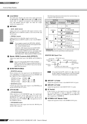
...'s USB interface. Channel fader GROUP 1-2 fader GROUP 3-4 fader STEREO OUT Master fader When connecting or disconnecting the USB cable be unable to register your computer using the supplied USB cable. Follow the on to your Cubase AI 4. Mixer Basics Quick Guide Mixer Basics This quick setup and operation guide covers everything from sleep/suspended/standby mode before making a con- Read the Software License Agreement at the end of this manual carefully, and install the software if you will need a working internet connection...
...'s USB interface. Channel fader GROUP 1-2 fader GROUP 3-4 fader STEREO OUT Master fader When connecting or disconnecting the USB cable be unable to register your computer using the supplied USB cable. Follow the on to your Cubase AI 4. Mixer Basics Quick Guide Mixer Basics This quick setup and operation guide covers everything from sleep/suspended/standby mode before making a con- Read the Software License Agreement at the end of this manual carefully, and install the software if you will need a working internet connection...
Owner's Manual
Page 8
... "studio" is basically confined to the "The recorded sound is very small, so even a tiny amount of noise will be relatively large, and will be affected by extremely high levels of speaker damage, turn the mixer's output controls-STEREO OUT Master fader , GROUP 1-2 fader and GROUP 3-4 fader-all connections are no more noise it 's something they're very good at. The reason for long cable runs. in microphone cables. In a word: "noise...
... "studio" is basically confined to the "The recorded sound is very small, so even a tiny amount of noise will be relatively large, and will be affected by extremely high levels of speaker damage, turn the mixer's output controls-STEREO OUT Master fader , GROUP 1-2 fader and GROUP 3-4 fader-all connections are no more noise it 's something they're very good at. The reason for long cable runs. in microphone cables. In a word: "noise...

Owner's Manual
Page 9
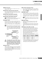
... is adjusted by the MONITOR/PHONES control. Mixer Basics Quick Guide 4 Step Adjusting Level and Tone Level Adjustment 1 The first step is to set to STEREO ( ). 5 Raise the STEREO OUT Master fader to the 0 dB position. 6 Set the channel faders to create the desired initial balance while monitoring via headphones or monitor speakers. MONITOR/PHONES control GAIN control PEAK indicator ON switch PFL switch ST switch Channel fader STEREO OUT Master fader MONITOR switch Tone Adjustment The MG mixer's compressors, 3-band equalizers and digital effects make it 's better to use EQ...
... is adjusted by the MONITOR/PHONES control. Mixer Basics Quick Guide 4 Step Adjusting Level and Tone Level Adjustment 1 The first step is to set to STEREO ( ). 5 Raise the STEREO OUT Master fader to the 0 dB position. 6 Set the channel faders to create the desired initial balance while monitoring via headphones or monitor speakers. MONITOR/PHONES control GAIN control PEAK indicator ON switch PFL switch ST switch Channel fader STEREO OUT Master fader MONITOR switch Tone Adjustment The MG mixer's compressors, 3-band equalizers and digital effects make it 's better to use EQ...
Owner's Manual
Page 10
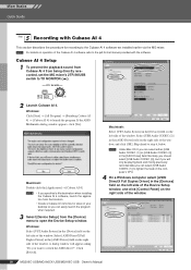
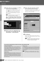
... computer's CPU. 4 On a Windows computer select [ASIO DirectX Full Duplex Driver] in the [Device] field on operation of the window. A dialog window will only be playing back and mixing previously recorded data you can select [USB Audio CODEC (1)] to the pdf-format manual provided with Cubase AI 4 This section describes the procedure for recording to launch the program. Macintosh: Select [VST Audio System] in the [Devices...
... computer's CPU. 4 On a Windows computer select [ASIO DirectX Full Duplex Driver] in the [Device] field on operation of the window. A dialog window will only be playing back and mixing previously recorded data you can select [USB Audio CODEC (1)] to the pdf-format manual provided with Cubase AI 4 This section describes the procedure for recording to launch the program. Macintosh: Select [VST Audio System] in the [Devices...
Owner's Manual
Page 12
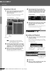
... Transport panel [Stop] button. 12 MG206C-USB/MG166CX-USB/MG166C-USB Owner's Manual If the [Record Enable] button is off, click it on. When recording is turned on . The various settings for the track to be created. Click the black area of the display. [Record Enable] button Track list 4 Play the instrument to be recorded, and adjust the MG mixer's GAIN controls, channel faders and STEREO OUT Master fader so that the Clipping indicator never light. Recording and Playback 1 Click the Transport panel [Record] button...
... Transport panel [Stop] button. 12 MG206C-USB/MG166CX-USB/MG166C-USB Owner's Manual If the [Record Enable] button is off, click it on. When recording is turned on . The various settings for the track to be created. Click the black area of the display. [Record Enable] button Track list 4 Play the instrument to be recorded, and adjust the MG mixer's GAIN controls, channel faders and STEREO OUT Master fader so that the Clipping indicator never light. Recording and Playback 1 Click the Transport panel [Record] button...
Owner's Manual
Page 13
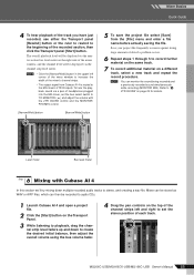
... section we'll try mixing down to create the desired initial balance, then adjust the overall volume using the bus volume fader. 4 Drag the pan controls on the top of the channel strips left corner of the mixer window to stereo, and creating a wav file. Mixer Basics Quick Guide 4 To hear playback of the track you have just recorded, use either the Transport panel [Rewind] button or the ruler...
... section we'll try mixing down to create the desired initial balance, then adjust the overall volume using the bus volume fader. 4 Drag the pan controls on the top of the channel strips left corner of the mixer window to stereo, and creating a wav file. Mixer Basics Quick Guide 4 To hear playback of the track you have just recorded, use either the Transport panel [Rewind] button or the ruler...
Owner's Manual
Page 14
... lower the channel fader a bit before adding an effect, since the effect can cause an increase in other parts of "grooves". Delay times can be adjusted to open the VST audio channel settings window. It's always a good idea to choose a reverb program that a totally washed-out mix sounds perfectly fine. Progress of the mixdown operation will be directly played back using the Windows Media Player, or iTunes on the music's tempo and density...
... lower the channel fader a bit before adding an effect, since the effect can cause an increase in other parts of "grooves". Delay times can be adjusted to open the VST audio channel settings window. It's always a good idea to choose a reverb program that a totally washed-out mix sounds perfectly fine. Progress of the mixdown operation will be directly played back using the Windows Media Player, or iTunes on the music's tempo and density...
Owner's Manual
Page 17
... complete sound cancellation. 6 GAIN Control Adjusts the input signal level. Band HIGH MID LOW Type Shelving Peaking Shelving Frequency 10 kHz 2.5 kHz* 100 Hz Maximum Cut/Boost ±15 dB * The monaural channel MID frequency can connect either of the three bands. R: Cold; S: Ground). Patching external devices via an INSERT jack requires a special cable such as the higher average output level that the PEAK indicator 9 lights only...
... complete sound cancellation. 6 GAIN Control Adjusts the input signal level. Band HIGH MID LOW Type Shelving Peaking Shelving Frequency 10 kHz 2.5 kHz* 100 Hz Maximum Cut/Boost ±15 dB * The monaural channel MID frequency can connect either of the three bands. R: Cold; S: Ground). Patching external devices via an INSERT jack requires a special cable such as the higher average output level that the PEAK indicator 9 lights only...
Owner's Manual
Page 18
... down to minimize noise. 18 MG206C-USB/MG166CX-USB/MG166C-USB Owner's Manual signals input to the R input (even channel) go to the GROUP 1 or 3 buses or to the STEREO L bus; When the switch is on the channel pre-fader signal is fed to the AUX buses. NOTE To send the signal to the GROUP 3/4 bus turn it on ( ). NOTE Set the fader sliders for monitoring. The BAL control knob sets the balance between the various channels. D ON Switch Turn this knob provides...
... down to minimize noise. 18 MG206C-USB/MG166CX-USB/MG166C-USB Owner's Manual signals input to the R input (even channel) go to the GROUP 1 or 3 buses or to the STEREO L bus; When the switch is on the channel pre-fader signal is fed to the AUX buses. NOTE To send the signal to the GROUP 3/4 bus turn it on ( ). NOTE Set the fader sliders for monitoring. The BAL control knob sets the balance between the various channels. D ON Switch Turn this knob provides...
Owner's Manual
Page 21
... IN/USB switch, and adjust the signal level using the 2TR IN/USB control in order to record the same signal that is on the mixer supplies +48V phantom power to all CAUTION the way down. 2 SEND Jacks (AUX, EFFECT) These impedance balanced* TRS phone jacks output the signals from an external effect device (reverb, delay, etc.). NOTE When this switch is being output via these jacks to connect to the input jacks of an multi-track recorder, external mixer, or other than condenser mics may...
... IN/USB switch, and adjust the signal level using the 2TR IN/USB control in order to record the same signal that is on the mixer supplies +48V phantom power to all CAUTION the way down. 2 SEND Jacks (AUX, EFFECT) These impedance balanced* TRS phone jacks output the signals from an external effect device (reverb, delay, etc.). NOTE When this switch is being output via these jacks to connect to the input jacks of an multi-track recorder, external mixer, or other than condenser mics may...
Owner's Manual
Page 22
...the level meter from that channel is set to TO STEREO ( ), the signals are using the RETURN2 AUX1, AUX2 and the STEREO controls. Switches Signals output via the GROUP 1-2 fader or GROUP 3-4 fader. itor playback signal and the signal being recorded separately. The "0" segment corresponds to the STEREO OUT jacks. 22 MG206C-USB/MG166CX-USB/MG166C-USB Owner's Manual G GROUP 1-2 Fader Adjusts the signal level sent to the GROUP OUT 3/ 4 jacks. STEREO L/R bus: STEREO ( ) GROUP 1/2 bus: GROUP ( ), 1-2 ( ) GROUP 3/4 bus: GROUP ( ), 3-4 ( ) • MONITOR Control Controls the...
...the level meter from that channel is set to TO STEREO ( ), the signals are using the RETURN2 AUX1, AUX2 and the STEREO controls. Switches Signals output via the GROUP 1-2 fader or GROUP 3-4 fader. itor playback signal and the signal being recorded separately. The "0" segment corresponds to the STEREO OUT jacks. 22 MG206C-USB/MG166CX-USB/MG166C-USB Owner's Manual G GROUP 1-2 Fader Adjusts the signal level sent to the GROUP OUT 3/ 4 jacks. STEREO L/R bus: STEREO ( ) GROUP 1/2 bus: GROUP ( ), 1-2 ( ) GROUP 3/4 bus: GROUP ( ), 3-4 ( ) • MONITOR Control Controls the...
Owner's Manual
Page 24
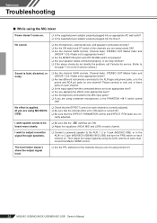
... Troubleshooting ■ While using the MG mixer Power doesn't come on ? 24 MG206C-USB/MG166CX-USB/MG166C-USB Owner's Manual No effect is applied. (If you are using turned ON? ❑ Are the channel GAIN controls, Channel fader, STEREO OUT Master fader and GROUP 1-2/3-4 fader set to appropriate levels? ❑ Are the MONITOR switch and 2TR IN/USB switch set properly? ❑ Are your speaker cables connected properly, or are they shorted? ❑ If the above checks do not identify the problem, call Yamaha for service...
... Troubleshooting ■ While using the MG mixer Power doesn't come on ? 24 MG206C-USB/MG166CX-USB/MG166C-USB Owner's Manual No effect is applied. (If you are using turned ON? ❑ Are the channel GAIN controls, Channel fader, STEREO OUT Master fader and GROUP 1-2/3-4 fader set to appropriate levels? ❑ Are the MONITOR switch and 2TR IN/USB switch set properly? ❑ Are your speaker cables connected properly, or are they shorted? ❑ If the above checks do not identify the problem, call Yamaha for service...
Owner's Manual
Page 26
... using . Click [Control Panel] from the [START] menu, and double-click the "Sounds and Audio Devices" icon to quit all applications you are not familiar with your computer's support center or support page on page 6 for the latest information. 26 MG206C-USB/MG166CX-USB/MG166C-USB Owner's Manual If the wave files you playing back a large number of free memory (more than 128 megabytes). Don't change these settings if you recording...
... using . Click [Control Panel] from the [START] menu, and double-click the "Sounds and Audio Devices" icon to quit all applications you are not familiar with your computer's support center or support page on page 6 for the latest information. 26 MG206C-USB/MG166CX-USB/MG166C-USB Owner's Manual If the wave files you playing back a large number of free memory (more than 128 megabytes). Don't change these settings if you recording...
Owner's Manual
Page 27
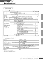
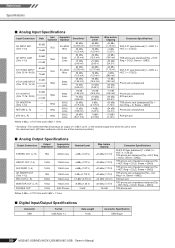
...fications USB Audio Input HPF Input equalization ±15 dB maximum Turn over/roll-off . Crosstalk (1 kHz) Maximum voltage gain (1 kHz) All faders and controls are nominal if not specified. STEREO OUT STEREO OUT, GROUP 1-2, GROUP 3-4 faders and one CH GROUP OUT fader at nominal level. Pre MONITOR Level 2x12 points LED meter (PEAK, +10, +6, +3, 0, -3, -6, -10, -15, -20, -25, -30 dB) STEREO/GROUP/PFL bus PEAK lights if the signal level reaches 3 dB...
...fications USB Audio Input HPF Input equalization ±15 dB maximum Turn over/roll-off . Crosstalk (1 kHz) Maximum voltage gain (1 kHz) All faders and controls are nominal if not specified. STEREO OUT STEREO OUT, GROUP 1-2, GROUP 3-4 faders and one CH GROUP OUT fader at nominal level. Pre MONITOR Level 2x12 points LED meter (PEAK, +10, +6, +3, 0, -3, -6, -10, -15, -20, -25, -30 dB) STEREO/GROUP/PFL bus PEAK lights if the signal level reaches 3 dB...
Owner's Manual
Page 28
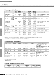
... unit is set to the maximum level. (All faders and level controls are at their maximum position.) ■ Analog Output Specifications Output Connectors Output Impedance Appropriate Impedance STEREO OUT (L, R) 75Ω 600Ω Lines GROUP OUT (1-4) 150Ω 10kΩ Lines AUX SEND (1-4) 150Ω 10kΩ Lines CH INSERT OUT (CHs 1-12) REC OUT (L, R) 75Ω 600Ω 10kΩ Lines 10kΩ Lines MONITOR OUT...
... unit is set to the maximum level. (All faders and level controls are at their maximum position.) ■ Analog Output Specifications Output Connectors Output Impedance Appropriate Impedance STEREO OUT (L, R) 75Ω 600Ω Lines GROUP OUT (1-4) 150Ω 10kΩ Lines AUX SEND (1-4) 150Ω 10kΩ Lines CH INSERT OUT (CHs 1-12) REC OUT (L, R) 75Ω 600Ω 10kΩ Lines 10kΩ Lines MONITOR OUT...
Owner's Manual
Page 30
... output level when the unit is set to the maximum level. (All faders and level controls are at their maximum position.) ■ Analog Output Specifications Output Connectors Output Impedance Appropriate Impedance STEREO OUT (L, R) 75Ω 600Ω Lines GROUP OUT (1-4) 150Ω 10kΩ Lines EFFECT/AUX* SEND 150Ω 10kΩ Lines CH INSERT OUT (CHs 1-8) REC OUT (L, R) 75Ω 600Ω 10kΩ Lines 10kΩ Lines MONITOR...
... output level when the unit is set to the maximum level. (All faders and level controls are at their maximum position.) ■ Analog Output Specifications Output Connectors Output Impedance Appropriate Impedance STEREO OUT (L, R) 75Ω 600Ω Lines GROUP OUT (1-4) 150Ω 10kΩ Lines EFFECT/AUX* SEND 150Ω 10kΩ Lines CH INSERT OUT (CHs 1-8) REC OUT (L, R) 75Ω 600Ω 10kΩ Lines 10kΩ Lines MONITOR...
Owner's Manual
Page 33
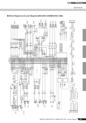
...] USB LIN USB D- RIN AUDIO D+ LO PCM2900 GND RO (Bus Powered) REG Vbus 12MHz Clip Level Clip Level Clip Level Clip Level AUX SEND *1 [+4dBu] GROUP OUT [+4dBu] AUX SEND *1 [Nominal:-6dB] GROUP Fader [Nominal:-10dB] ST Master [Nominal:-10dB] ST OUT [+4dBu] MONITOR OUT [+4dBu] REC OUT [-7.8dBu] PHONES [3mW @ 40ohms] MONI/PHONES [Nominal:-16dB] +30dBu +20dBu +10dBu 0dBu -10dBu -20dBu -30dBu ■ Block Diagram and Level Diagram (MG166CX-USB/MG166C-USB) Reference Specifications
...] USB LIN USB D- RIN AUDIO D+ LO PCM2900 GND RO (Bus Powered) REG Vbus 12MHz Clip Level Clip Level Clip Level Clip Level AUX SEND *1 [+4dBu] GROUP OUT [+4dBu] AUX SEND *1 [Nominal:-6dB] GROUP Fader [Nominal:-10dB] ST Master [Nominal:-10dB] ST OUT [+4dBu] MONITOR OUT [+4dBu] REC OUT [-7.8dBu] PHONES [3mW @ 40ohms] MONI/PHONES [Nominal:-16dB] +30dBu +20dBu +10dBu 0dBu -10dBu -20dBu -30dBu ■ Block Diagram and Level Diagram (MG166CX-USB/MG166C-USB) Reference Specifications


