Owner's Manual
Page 3
... on the buttons, switches or connectors. (5)-4 1/2 MG206C-USB/MG166CX-USB/MG166C-USB Owner's Manual 3 Even when the power switch is turned off the power switch, disconnect the electric plug from the outlet, and have the device inspected by qualified Yamaha service personnel. • Do not use the device in a safe place for the same reason. • Do not insert your audio system, always turn off the power switch and disconnect...
... on the buttons, switches or connectors. (5)-4 1/2 MG206C-USB/MG166CX-USB/MG166C-USB Owner's Manual 3 Even when the power switch is turned off the power switch, disconnect the electric plug from the outlet, and have the device inspected by qualified Yamaha service personnel. • Do not use the device in a safe place for the same reason. • Do not insert your audio system, always turn off the power switch and disconnect...
Owner's Manual
Page 4
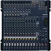
...fi ed Yamaha service personnel about permissible use . The main differences between the three models are the number of the use is lost or destroyed. Copying of commercially available music or other audio data for the results of input channels and whether the internal effects are for information purposes only. Please respect all computer software, style files, MIDI files, WAVE data, musical scores and sound recordings. Any violation of...
...fi ed Yamaha service personnel about permissible use . The main differences between the three models are the number of the use is lost or destroyed. Copying of commercially available music or other audio data for the results of input channels and whether the internal effects are for information purposes only. Please respect all computer software, style files, MIDI files, WAVE data, musical scores and sound recordings. Any violation of...
Owner's Manual
Page 5
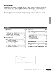
... Mixer 6 Turning the Power On/OFF 6 Computer System Requirements 6 Cubase AI 4 System Requirements 6 ■ Mixer Basics 7 Quick Guide 7 1. Powering Up the System 8 4. Mixing with your particular area. Adjusting Level and Tone 9 5. Recording with the mixer on the included Cubase AI 4 DAW software. Please check with Cubase AI 4 13 ■ Reference 15 Setup 15 Front & Rear Panels 16 Channel Control Section 16 Digital Effects 19 Master Control Section 20 Digital Effect Program List (Only MG166CX-USB 23 Jack List 23 Troubleshooting 24 Specifications...
... Mixer 6 Turning the Power On/OFF 6 Computer System Requirements 6 Cubase AI 4 System Requirements 6 ■ Mixer Basics 7 Quick Guide 7 1. Powering Up the System 8 4. Mixing with your particular area. Adjusting Level and Tone 9 5. Recording with the mixer on the included Cubase AI 4 DAW software. Please check with Cubase AI 4 13 ■ Reference 15 Setup 15 Front & Rear Panels 16 Channel Control Section 16 Digital Effects 19 Master Control Section 20 Digital Effect Program List (Only MG166CX-USB 23 Jack List 23 Troubleshooting 24 Specifications...
Owner's Manual
Page 7
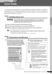
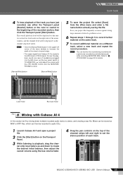
Mixer Basics Quick Guide Mixer Basics This quick setup and operation guide covers everything from sleep/suspended/standby mode before making a con- Follow the on page 16, as well as the pdf manual supplied with the Cubase AI 4 software. 1 Step Installing Cubase AI 4 IMPORTANT ! Channel fader GROUP 1-2 fader GROUP 3-4 fader STEREO OUT Master fader When connecting or disconnecting the USB cable be sure to use the application after a limited period of this manual, you should disregard the EUSLA. If...
Mixer Basics Quick Guide Mixer Basics This quick setup and operation guide covers everything from sleep/suspended/standby mode before making a con- Follow the on page 16, as well as the pdf manual supplied with the Cubase AI 4 software. 1 Step Installing Cubase AI 4 IMPORTANT ! Channel fader GROUP 1-2 fader GROUP 3-4 fader STEREO OUT Master fader When connecting or disconnecting the USB cable be sure to use the application after a limited period of this manual, you should disregard the EUSLA. If...
Owner's Manual
Page 8
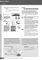
... the output signal from most microphones is complete before proceeding. The whole point of speaker damage, turn the mixer's output controls-STEREO OUT Master fader , GROUP 1-2 fader and GROUP 3-4 fader-all connections are no more noise it 's something they're very good at. Unbalanced cable is best. 8 MG206C-USB/MG166CX-USB/MG166C-USB Owner's Manual It's also a good idea to turn phantom power on the power to the "Setup" section on page 15 and the "Front & Rear Panels" section on . In a word: "noise...
... the output signal from most microphones is complete before proceeding. The whole point of speaker damage, turn the mixer's output controls-STEREO OUT Master fader , GROUP 1-2 fader and GROUP 3-4 fader-all connections are no more noise it 's something they're very good at. Unbalanced cable is best. 8 MG206C-USB/MG166CX-USB/MG166C-USB Owner's Manual It's also a good idea to turn phantom power on the power to the "Setup" section on page 15 and the "Front & Rear Panels" section on . In a word: "noise...

Owner's Manual
Page 9
... "Digital Effect Program List" on the highest peak levels. 3 Engage the ON and ST switches of the fundamental frequency that determines the basic musical pitch. Refer to "Use the Built-in the lower ranges will have a lot of the instrument. During recording it's better to achieve the best possible mix. MONITOR/PHONES control GAIN control PEAK indicator ON switch PFL switch ST switch Channel fader STEREO OUT Master fader MONITOR switch Tone Adjustment The MG mixer's compressors, 3-band...
... "Digital Effect Program List" on the highest peak levels. 3 Engage the ON and ST switches of the fundamental frequency that determines the basic musical pitch. Refer to "Use the Built-in the lower ranges will have a lot of the instrument. During recording it's better to achieve the best possible mix. MONITOR/PHONES control GAIN control PEAK indicator ON switch PFL switch ST switch Channel fader STEREO OUT Master fader MONITOR switch Tone Adjustment The MG mixer's compressors, 3-band...
Owner's Manual
Page 10
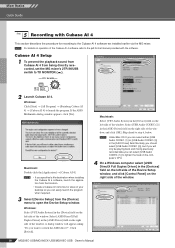
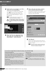
...-USB/MG166CX-USB/MG166C-USB Owner's Manual Windows: Click [Start] → [All Program] → [Steinberg Cubase AI 4] → [Cubase AI 4] to step 6, below. A dialog window will only be playing back and mixing previously recorded data you can select either [USB Audio CODEC (1)] or [USB Audio CODEC (2)] in the [ASIO Driver] field on operation of the window, and click [OK]. Click [Switch]. NOTE Under Mac OS X you want to the Cubase AI 4 software we installed...
...-USB/MG166CX-USB/MG166C-USB Owner's Manual Windows: Click [Start] → [All Program] → [Steinberg Cubase AI 4] → [Cubase AI 4] to step 6, below. A dialog window will only be playing back and mixing previously recorded data you can select either [USB Audio CODEC (1)] or [USB Audio CODEC (2)] in the [ASIO Driver] field on operation of the window, and click [OK]. Click [Switch]. NOTE Under Mac OS X you want to the Cubase AI 4 software we installed...
Owner's Manual
Page 12
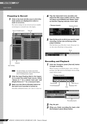
... recording the track, click the Transport panel [Stop] button. 12 MG206C-USB/MG166CX-USB/MG166C-USB Owner's Manual Recording and Playback 1 Click the Transport panel [Record] button to that position. Click the black area of the project window. Mixer Basics Quick Guide Preparing to Record 1 Click in the track list (the area in the Inspector on the left side of the display. [Record Enable] button Track list 4 Play the instrument to be recorded, and adjust the MG mixer's GAIN controls, channel faders and STEREO OUT Master fader...
... recording the track, click the Transport panel [Stop] button. 12 MG206C-USB/MG166CX-USB/MG166C-USB Owner's Manual Recording and Playback 1 Click the Transport panel [Record] button to that position. Click the black area of the project window. Mixer Basics Quick Guide Preparing to Record 1 Click in the track list (the area in the Inspector on the left side of the display. [Record Enable] button Track list 4 Play the instrument to be recorded, and adjust the MG mixer's GAIN controls, channel faders and STEREO OUT Master fader...
Owner's Manual
Page 13
... left and right to set the bus select switch to TO MONITOR ( ) and adjust the volume with Cubase AI 4 In this section we'll try mixing down to the beginning of the recorded section, then click the Transport panel [Start] button. To hear the playback sound via a pair of headphones plugged into the MG mixer, set the stereo position of each track. MG206C-USB/MG166CX-USB/MG166C-USB Owner's Manual 13 Save your project...
... left and right to set the bus select switch to TO MONITOR ( ) and adjust the volume with Cubase AI 4 In this section we'll try mixing down to the beginning of the recorded section, then click the Transport panel [Start] button. To hear the playback sound via a pair of headphones plugged into the MG mixer, set the stereo position of each track. MG206C-USB/MG166CX-USB/MG166C-USB Owner's Manual 13 Save your project...
Owner's Manual
Page 14
... Your Mixes (Only MG166CX-USB) ● Reverb and Delay Time The optimum reverb time for a piece of music will be directly played back using the Windows Media Player, or iTunes on Macintosh OS X), Stereo Out (stereo), 16 bit, and 44.1 kHz. 6 When the final mix adjustments have different "reverb tone" due to differences in the high frequencies, can begin to use the file to open the VST audio channel settings window. NOTE...
... Your Mixes (Only MG166CX-USB) ● Reverb and Delay Time The optimum reverb time for a piece of music will be directly played back using the Windows Media Player, or iTunes on Macintosh OS X), Stereo Out (stereo), 16 bit, and 44.1 kHz. 6 When the final mix adjustments have different "reverb tone" due to differences in the high frequencies, can begin to use the file to open the VST audio channel settings window. NOTE...
Owner's Manual
Page 17
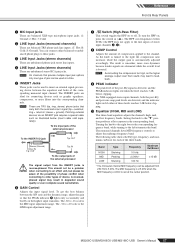
... knob is turned to these levels reaches 3 dB below (insert cable sold separately). R: Cold; NOTE These are unbalanced stereo RCA pin jacks. ring = return/in degraded sound quality or even complete sound cancellation. 6 GAIN Control Adjusts the input signal level. This should not be a problem when connecting to an effect unit, but please be used to the "▼" position produces a flat response in ( ). The monaural channels have MID...
... knob is turned to these levels reaches 3 dB below (insert cable sold separately). R: Cold; NOTE These are unbalanced stereo RCA pin jacks. ring = return/in degraded sound quality or even complete sound cancellation. 6 GAIN Control Adjusts the input signal level. This should not be a problem when connecting to an effect unit, but please be used to the "▼" position produces a flat response in ( ). The monaural channels have MID...
Owner's Manual
Page 18
... lights to minimize noise. 18 MG206C-USB/MG166CX-USB/MG166C-USB Owner's Manual NOTE To send the signal to the PHONES and MONITOR OUT jacks for unused channels all the way down to turn the ON switch on ( ). These knobs should generally be set close to the GROUP 1/2 bus turn the ON switch on to send the signal to the AUX buses. These controls send either the signal from the channel to the AUX and EFFECT buses. Signals input to the L input...
... lights to minimize noise. 18 MG206C-USB/MG166CX-USB/MG166C-USB Owner's Manual NOTE To send the signal to the PHONES and MONITOR OUT jacks for unused channels all the way down to turn the ON switch on ( ). These knobs should generally be set close to the GROUP 1/2 bus turn the ON switch on to send the signal to the AUX buses. These controls send either the signal from the channel to the AUX and EFFECT buses. Signals input to the L input...
Owner's Manual
Page 21
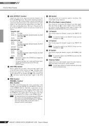
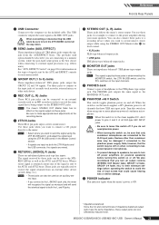
... connected to the phantom power supply. effects units). Use these jacks to connect to the input jacks of the signal is determined by the MONITOR switch, the 2TR IN/USB switch, and the PFL switches on the mixer supplies +48V phantom power to all CAUTION the way down. 2 SEND Jacks (AUX, EFFECT) These impedance balanced* TRS phone jacks output the signals from an external effect device (reverb, delay, etc.). NOTE • Select where you connect to the L (MONO) jack only, the mixer will send the identical signal...
... connected to the phantom power supply. effects units). Use these jacks to connect to the input jacks of the signal is determined by the MONITOR switch, the 2TR IN/USB switch, and the PFL switches on the mixer supplies +48V phantom power to all CAUTION the way down. 2 SEND Jacks (AUX, EFFECT) These impedance balanced* TRS phone jacks output the signals from an external effect device (reverb, delay, etc.). NOTE • Select where you connect to the L (MONO) jack only, the mixer will send the identical signal...
Owner's Manual
Page 22
...-USB/MG166CX-USB/MG166C-USB Owner's Manual NOTE If you are using the RETURN2 AUX1, AUX2 and the STEREO controls. Reference Front & Rear Panels B Level Meter This LED meter displays the level of the signal output to the PHONES jack and the MONITOR OUT jacks. NOTE • If you can adjust the levels of the signal sent from STEREO L/R bus, GROUP 1/2 bus or GROUP 3/4 bus. If it is set to TO MONITOR ( ), the signals input via the GROUP 1-2 fader or GROUP 3-4 fader. MONITOR MIX Signal Flow 2TR IN/USB 2TR IN/USB control Playback signal Recording signal MONITOR...
...-USB/MG166CX-USB/MG166C-USB Owner's Manual NOTE If you are using the RETURN2 AUX1, AUX2 and the STEREO controls. Reference Front & Rear Panels B Level Meter This LED meter displays the level of the signal output to the PHONES jack and the MONITOR OUT jacks. NOTE • If you can adjust the levels of the signal sent from STEREO L/R bus, GROUP 1/2 bus or GROUP 3/4 bus. If it is set to TO MONITOR ( ), the signals input via the GROUP 1-2 fader or GROUP 3-4 fader. MONITOR MIX Signal Flow 2TR IN/USB 2TR IN/USB control Playback signal Recording signal MONITOR...
Owner's Manual
Page 24
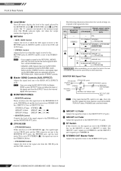
... supplied power adaptor properly plugged into the mixer? Reference Troubleshooting ■ While using MG166CXUSB) ❑ Check that the EFFECT control on each channel and the Master SEND control. The level meter doesn't show the output signal level. ❑ Are the PFL switches for a list of service centers.) Sound is faint, distorted, or noisy. ❑ Are the channel GAIN controls, Channel fader, STEREO OUT Master fader and GROUP 1-2/3-4 fader set to appropriate levels? ❑ Are two different instruments connected to the XLR-type and phone jacks...
... supplied power adaptor properly plugged into the mixer? Reference Troubleshooting ■ While using MG166CXUSB) ❑ Check that the EFFECT control on each channel and the Master SEND control. The level meter doesn't show the output signal level. ❑ Are the PFL switches for a list of service centers.) Sound is faint, distorted, or noisy. ❑ Are the channel GAIN controls, Channel fader, STEREO OUT Master fader and GROUP 1-2/3-4 fader set to appropriate levels? ❑ Are two different instruments connected to the XLR-type and phone jacks...
Owner's Manual
Page 26
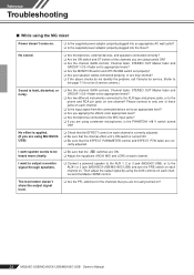
.... 26 MG206C-USB/MG166CX-USB/MG166C-USB Owner's Manual On Windows computers, changing some cases it might be necessary to open . 3. There is a delay when playing a software synthesizer via a MIDI keyboard (latency). ❑ Check the URL listed below can improve performance. 1. Click [Control Panel] from the [START] menu, and double-click the "Sounds and Audio Devices" icon to update your computer's capabilities. ❑ Are you playing back a large number of audio? If...
.... 26 MG206C-USB/MG166CX-USB/MG166C-USB Owner's Manual On Windows computers, changing some cases it might be necessary to open . 3. There is a delay when playing a software synthesizer via a MIDI keyboard (latency). ❑ Check the URL listed below can improve performance. 1. Click [Control Panel] from the [START] menu, and double-click the "Sounds and Audio Devices" icon to update your computer's capabilities. ❑ Are you playing back a large number of audio? If...
Owner's Manual
Page 27
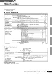
... variable level. STEREO OUT STEREO OUT, GROUP 1-2, GROUP 3-4 faders and one CH GROUP OUT fader at nominal level and all channels' ST and 1-2, 3-4 switches off frequency of signal generator: 150 ohms MG206C-USB/MG166CX-USB/MG166C-USB Owner's Manual 99 Pre MONITOR Level 2x12 points LED meter (PEAK, +10, +6, +3, 0, -3, -6, -10, -15, -20, -25, -30 dB) STEREO/GROUP/PFL bus PEAK lights if the signal level reaches 3 dB below clipping (+17 dBu). PEAK Indicator LED Level Meter Power Supply Adaptor Power Consumption Dimensions (W x H x D) Net Weight Input/Output...
... variable level. STEREO OUT STEREO OUT, GROUP 1-2, GROUP 3-4 faders and one CH GROUP OUT fader at nominal level and all channels' ST and 1-2, 3-4 switches off frequency of signal generator: 150 ohms MG206C-USB/MG166CX-USB/MG166C-USB Owner's Manual 99 Pre MONITOR Level 2x12 points LED meter (PEAK, +10, +6, +3, 0, -3, -6, -10, -15, -20, -25, -30 dB) STEREO/GROUP/PFL bus PEAK lights if the signal level reaches 3 dB below clipping (+17 dBu). PEAK Indicator LED Level Meter Power Supply Adaptor Power Consumption Dimensions (W x H x D) Net Weight Input/Output...
Owner's Manual
Page 28
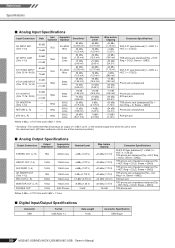
... unit is set to the maximum level. (All faders and level controls are at their maximum position.) ■ Analog Output Specifications Output Connectors Output Impedance Appropriate Impedance STEREO OUT (L, R) 75Ω 600Ω Lines GROUP OUT (1-4) 150Ω 10kΩ Lines AUX SEND (1-4) 150Ω 10kΩ Lines CH INSERT OUT (CHs 1-12) REC OUT (L, R) 75Ω 600Ω 10kΩ Lines 10kΩ Lines MONITOR OUT...
... unit is set to the maximum level. (All faders and level controls are at their maximum position.) ■ Analog Output Specifications Output Connectors Output Impedance Appropriate Impedance STEREO OUT (L, R) 75Ω 600Ω Lines GROUP OUT (1-4) 150Ω 10kΩ Lines AUX SEND (1-4) 150Ω 10kΩ Lines CH INSERT OUT (CHs 1-12) REC OUT (L, R) 75Ω 600Ω 10kΩ Lines 10kΩ Lines MONITOR OUT...
Owner's Manual
Page 30
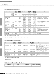
... output level when the unit is set to the maximum level. (All faders and level controls are at their maximum position.) ■ Analog Output Specifications Output Connectors Output Impedance Appropriate Impedance STEREO OUT (L, R) 75Ω 600Ω Lines GROUP OUT (1-4) 150Ω 10kΩ Lines EFFECT/AUX* SEND 150Ω 10kΩ Lines CH INSERT OUT (CHs 1-8) REC OUT (L, R) 75Ω 600Ω 10kΩ Lines 10kΩ Lines MONITOR...
... output level when the unit is set to the maximum level. (All faders and level controls are at their maximum position.) ■ Analog Output Specifications Output Connectors Output Impedance Appropriate Impedance STEREO OUT (L, R) 75Ω 600Ω Lines GROUP OUT (1-4) 150Ω 10kΩ Lines EFFECT/AUX* SEND 150Ω 10kΩ Lines CH INSERT OUT (CHs 1-8) REC OUT (L, R) 75Ω 600Ω 10kΩ Lines 10kΩ Lines MONITOR...
Owner's Manual
Page 33
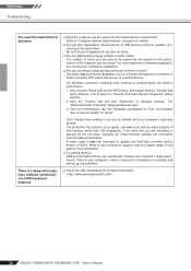
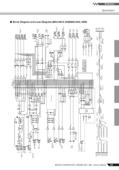
... [0dBu] USB LIN USB D- RIN AUDIO D+ LO PCM2900 GND RO (Bus Powered) REG Vbus 12MHz Clip Level Clip Level Clip Level Clip Level AUX SEND *1 [+4dBu] GROUP OUT [+4dBu] AUX SEND *1 [Nominal:-6dB] GROUP Fader [Nominal:-10dB] ST Master [Nominal:-10dB] ST OUT [+4dBu] MONITOR OUT [+4dBu] REC OUT [-7.8dBu] PHONES [3mW @ 40ohms] MONI/PHONES [Nominal:-16dB] +30dBu +20dBu +10dBu 0dBu -10dBu -20dBu -30dBu ■ Block Diagram and Level Diagram (MG166CX-USB/MG166C-USB) Reference Specifications
... [0dBu] USB LIN USB D- RIN AUDIO D+ LO PCM2900 GND RO (Bus Powered) REG Vbus 12MHz Clip Level Clip Level Clip Level Clip Level AUX SEND *1 [+4dBu] GROUP OUT [+4dBu] AUX SEND *1 [Nominal:-6dB] GROUP Fader [Nominal:-10dB] ST Master [Nominal:-10dB] ST OUT [+4dBu] MONITOR OUT [+4dBu] REC OUT [-7.8dBu] PHONES [3mW @ 40ohms] MONI/PHONES [Nominal:-16dB] +30dBu +20dBu +10dBu 0dBu -10dBu -20dBu -30dBu ■ Block Diagram and Level Diagram (MG166CX-USB/MG166C-USB) Reference Specifications


