
Ls9 Editor Owner's Manual
Page 13
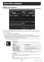
... of the internal head amp or of USB memory recorder output RACK1A, RACK1B... The parameters shown in the window can be assigned to the INPUT CH, from the [View] menu or the menu that appears when you 're editing online with the LS9-32. 1 A Input patch Click here to select the input source... that will be viewed only if LS9-32 is selected in a slot 2TR IN L, 2TR IN R L/R channels of the 2TR DIN jack PB OUT L, PB...
... of the internal head amp or of USB memory recorder output RACK1A, RACK1B... The parameters shown in the window can be assigned to the INPUT CH, from the [View] menu or the menu that appears when you 're editing online with the LS9-32. 1 A Input patch Click here to select the input source... that will be viewed only if LS9-32 is selected in a slot 2TR IN L, 2TR IN R L/R channels of the 2TR DIN jack PB OUT L, PB...
Ls9 Editor Owner's Manual
Page 18
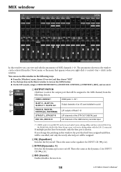
... 2TR OUT DIGITAL jack REC IN L, REC IN R L/R channels of the USB memory recorder input (*) OMNI jacks 9-16 and SLOT2 can access this window in the following choices. If you 're editing online with the LS9-32 connected. B EQ (Equalizer) Switches the EQ on/off . You can be assigned. ... INPUT CH (➥ p.14). D INS (Insert) Enables/disables the insert-in a slot 4 RACK1A, RACK1B... This is shown. If multiple patches have selected LS9-32 in the Model Select field of fline and have been made, only the first port is the same as the equalizer for...
... 2TR OUT DIGITAL jack REC IN L, REC IN R L/R channels of the USB memory recorder input (*) OMNI jacks 9-16 and SLOT2 can access this window in the following choices. If you 're editing online with the LS9-32 connected. B EQ (Equalizer) Switches the EQ on/off . You can be assigned. ... INPUT CH (➥ p.14). D INS (Insert) Enables/disables the insert-in a slot 4 RACK1A, RACK1B... This is shown. If multiple patches have selected LS9-32 in the Model Select field of fline and have been made, only the first port is the same as the equalizer for...

Ls9 Editor Owner's Manual
Page 36
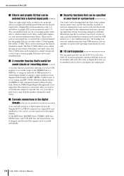
...the USB memory recorder input (*) OMNI jacks 9-16 and SLOT2 can set it to the nominal value (0.00 dB) by holding down the (< >) key of the LS9's panel. B Fader Adjusts the input level of the Mixer Setup window, or if you 're editing offline and have selected LS9-32 in the numerical... box immediately below. This is linked with the LS9-32 connected. You can be patched. ❏ RECALL SAFE/MUTE SAFE These enable/disable Recall Safe and Mute Safe ...
...the USB memory recorder input (*) OMNI jacks 9-16 and SLOT2 can set it to the nominal value (0.00 dB) by holding down the (< >) key of the LS9's panel. B Fader Adjusts the input level of the Mixer Setup window, or if you 're editing offline and have selected LS9-32 in the numerical... box immediately below. This is linked with the LS9-32 connected. You can be patched. ❏ RECALL SAFE/MUTE SAFE These enable/disable Recall Safe and Mute Safe ...

Ls9 Editor Owner's Manual
Page 59
... input to adjust timerelated parameters such as the effect type, this indicates the gain reduction amount for the currently selected effect type. 59 LS9 Editor Owner's Manual If the MIDI CLK button is selected, this switches between the standard parameter screen and the dedicated GUI screen. Q...the BPM (Beats Per Minute) in the numerical box, or repeatedly click the TAP TEMPO button at the desired tempo. O P Q P PLAY/REC (Play/Record) buttons If "042 FREEZE" is selected as the effect type, you to the original sound. 0 (%) outputs only the original sound, and 100 (%) outputs...
... input to adjust timerelated parameters such as the effect type, this indicates the gain reduction amount for the currently selected effect type. 59 LS9 Editor Owner's Manual If the MIDI CLK button is selected, this switches between the standard parameter screen and the dedicated GUI screen. Q...the BPM (Beats Per Minute) in the numerical box, or repeatedly click the TAP TEMPO button at the desired tempo. O P Q P PLAY/REC (Play/Record) buttons If "042 FREEZE" is selected as the effect type, you to the original sound. 0 (%) outputs only the original sound, and 100 (%) outputs...

Owner's Manual
Page 6
... About the USB memory recorder 105 Assigning channels to USB memory 108 Playing back audio files from USB memory ........110 Editing the title list 112 Linking scene recall with audio file playback ......113 6 LS9-16/32 Owner's Manual Parts and their function 15 Top panel 15 Rear panel 23... ON FADER mode) .....65 6. Introduction 9 Thank you 9 An overview of the LS9 9 Differences between the LS9-16 and LS9-32 ......... 11 Number of INPUT channels 11 Rear panel 11 Top panel 12 Other 13 The LS9's channel structure 13 About the MIX bus types (VARI / FIXED 14 About word clock...
... About the USB memory recorder 105 Assigning channels to USB memory 108 Playing back audio files from USB memory ........110 Editing the title list 112 Linking scene recall with audio file playback ......113 6 LS9-16/32 Owner's Manual Parts and their function 15 Top panel 15 Rear panel 23... ON FADER mode) .....65 6. Introduction 9 Thank you 9 An overview of the LS9 9 Differences between the LS9-16 and LS9-32 ......... 11 Number of INPUT channels 11 Rear panel 11 Top panel 12 Other 13 The LS9's channel structure 13 About the MIX bus types (VARI / FIXED 14 About word clock...

Owner's Manual
Page 7
...About the graphic EQ 161 Inserting a GEQ in 189 Changing the password 191 Editing a user authentication key 192 Changing the user level 192 LS9-16/32 Owner's Manual 7 Grouping and linking 121 About mute groups 121 Using mute groups 121 Using the MUTE GROUP screen to operate mute groups ...121 Using the SELECTED CH VIEW screen to operate the USB memory recorder 186 19. User settings (Security) 187 User Level settings 187 User types...
...About the graphic EQ 161 Inserting a GEQ in 189 Changing the password 191 Editing a user authentication key 192 Changing the user level 192 LS9-16/32 Owner's Manual 7 Grouping and linking 121 About mute groups 121 Using mute groups 121 Using the MUTE GROUP screen to operate mute groups ...121 Using the SELECTED CH VIEW screen to operate the USB memory recorder 186 19. User settings (Security) 187 User Level settings 187 User types...
Owner's Manual
Page 10
...rear panel provides one bands. These can be used simultaneously. ■ A recorder function that's useful for playback. Passwords can be specified for any fifteen of the thirty-one slot (LS9-16) or two slots (LS9-32) in racks 5-8. Information specific to each non-administrator user can be...the functionality available to each user (user level, system settings, and user-defined key settings) can be stored on USB memory as the Yamaha M7CL or PM5D connected via a digital I /O cards can be installed in a single virtual rack, a total of up to sixteen graphic EQ ...
...rear panel provides one bands. These can be used simultaneously. ■ A recorder function that's useful for playback. Passwords can be specified for any fifteen of the thirty-one slot (LS9-16) or two slots (LS9-32) in racks 5-8. Information specific to each non-administrator user can be...the functionality available to each user (user level, system settings, and user-defined key settings) can be stored on USB memory as the Yamaha M7CL or PM5D connected via a digital I /O cards can be installed in a single virtual rack, a total of up to sixteen graphic EQ ...

Owner's Manual
Page 19
...the LS9-32 LAYER key / module LAYER [1-32] key LAYER [33-64] key LAYER [MASTER] key 1-16 CH 1-16 CH 33-48 MIX 1-16 17-24 CH 17-24 CH 49-56 MATRIX 1-8 25-31 CH 25-31 CH 57-63 - 32 CH 32 CH 64 MONO ST IN 1-4 ST IN 1-4 ST IN 1-4 - E [RECORDER] ... effect that will be operated from the channel module section (→ p. 17) and ST IN section (→ p. 17). 1 2 1 2 3 4 3 4 LS9-16 LS9-32 1 LAYER [1-16] {LAYER [1-32]} key B LAYER [17-32] {LAYER [33-64]} key C LAYER [MASTER] key These keys assign fixed preset combinations of channels that is as follows. C [SETUP] key...
...the LS9-32 LAYER key / module LAYER [1-32] key LAYER [33-64] key LAYER [MASTER] key 1-16 CH 1-16 CH 33-48 MIX 1-16 17-24 CH 17-24 CH 49-56 MATRIX 1-8 25-31 CH 25-31 CH 57-63 - 32 CH 32 CH 64 MONO ST IN 1-4 ST IN 1-4 ST IN 1-4 - E [RECORDER] ... effect that will be operated from the channel module section (→ p. 17) and ST IN section (→ p. 17). 1 2 1 2 3 4 3 4 LS9-16 LS9-32 1 LAYER [1-16] {LAYER [1-32]} key B LAYER [17-32] {LAYER [33-64]} key C LAYER [MASTER] key These keys assign fixed preset combinations of channels that is as follows. C [SETUP] key...
Owner's Manual
Page 25
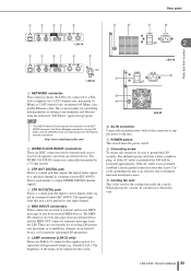
...-4-31 connector that supplies power to a separately sold gooseneck lamp (e.g., Yamaha LA1L). This is the vent for remotely operating LS9 parameters. H MIDI IN/OUT connectors These connectors are used mainly for recording LS9 parameter operations or scene/library changes on /off. The MIDI IN...consumer format (IEC-60958). Rear panel 4 5 67 8 L M K J Parts and their function 4 5 67 LS9-16 8 9 2 LS9-16 J K LS9-32 D NETWORK connector This connector allows the LS9 to be careful not to block this vent. The brightness of a specified channel in the screen. NOTE &#...
...-4-31 connector that supplies power to a separately sold gooseneck lamp (e.g., Yamaha LA1L). This is the vent for remotely operating LS9 parameters. H MIDI IN/OUT connectors These connectors are used mainly for recording LS9 parameter operations or scene/library changes on /off. The MIDI IN...consumer format (IEC-60958). Rear panel 4 5 67 8 L M K J Parts and their function 4 5 67 LS9-16 8 9 2 LS9-16 J K LS9-32 D NETWORK connector This connector allows the LS9 to be careful not to block this vent. The brightness of a specified channel in the screen. NOTE &#...
Owner's Manual
Page 30
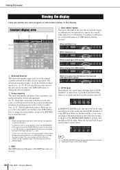
...protected scenes. C MIDI The MIDI indicator will be black. Constant display area D User name / status This shows the name of the scene number. 30 LS9-16/32 Owner's Manual An "R" (Read Only) indication is currently logged- When on, the knob will be a color corresponding to recall the scene. Viewing the ... or talkback is on, or if internal memory or USB memory is being accessed. 3 When oscillator is on 4 When talkback is on While recording to USB memory While playing from USB memory 1 Selected channel This shows the number, name, and icon of the scene that is shown here ...
...protected scenes. C MIDI The MIDI indicator will be black. Constant display area D User name / status This shows the name of the scene number. 30 LS9-16/32 Owner's Manual An "R" (Read Only) indication is currently logged- When on, the knob will be a color corresponding to recall the scene. Viewing the ... or talkback is on, or if internal memory or USB memory is being accessed. 3 When oscillator is on 4 When talkback is on While recording to USB memory While playing from USB memory 1 Selected channel This shows the number, name, and icon of the scene that is shown here ...
Owner's Manual
Page 43
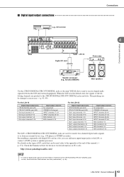
... CD recorder 4 Digital I /O cards. http://www.yamahaproaudio.com/ NOTE • In order for the most recent information on the types of this manual (→ p. 274). For the LS9-16 Digital...output channels No assignment STEREO L/R channel INPUT channels 17-24 INPUT channels 25-32 MIX channels 1-8 MIX channels 9-16 For the LS9-32 Digital input/output jacks 2TR IN DIGITAL jack (L/R) 2TR OUT DIGITAL jack (L/R)...MIX channels 9-16 The LS9's 2TR IN DIGITAL/2TR OUT DIGITAL jacks are patched to the LS9, or connect a DAW system or speaker processor. Check the Yamaha website for digital audio...
... CD recorder 4 Digital I /O cards. http://www.yamahaproaudio.com/ NOTE • In order for the most recent information on the types of this manual (→ p. 274). For the LS9-16 Digital...output channels No assignment STEREO L/R channel INPUT channels 17-24 INPUT channels 25-32 MIX channels 1-8 MIX channels 9-16 For the LS9-32 Digital input/output jacks 2TR IN DIGITAL jack (L/R) 2TR OUT DIGITAL jack (L/R)...MIX channels 9-16 The LS9's 2TR IN DIGITAL/2TR OUT DIGITAL jacks are patched to the LS9, or connect a DAW system or speaker processor. Check the Yamaha website for digital audio...
Owner's Manual
Page 46
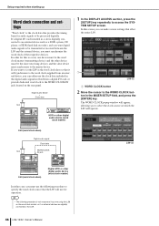
... synchronize the word clock of the respective devices. HINT • The following procedure to specify the word clock source that affect the entire LS9. 1 LS9-32 1 WORD CLOCK button 2 Move the cursor to the WORD CLOCK button in the MIXER SETUP field, and press the [ENTER]...LS9-32 LS9 (word clock slave) Digital MTR or other device must be the word clock master (transmitting device) and the other digital audio device (word clock master) In either use the following procedure is digitally connected to an external device such as a DAW system, CD player, or HDR (hard disk recorder...
... synchronize the word clock of the respective devices. HINT • The following procedure to specify the word clock source that affect the entire LS9. 1 LS9-32 1 WORD CLOCK button 2 Move the cursor to the WORD CLOCK button in the MIXER SETUP field, and press the [ENTER]...LS9-32 LS9 (word clock slave) Digital MTR or other device must be the word clock master (transmitting device) and the other digital audio device (word clock master) In either use the following procedure is digitally connected to an external device such as a DAW system, CD player, or HDR (hard disk recorder...

Owner's Manual
Page 53
... / POST PAN L ON (PRE FADER)PFL / (POST ON)AFL / POST PAN R ON CUE L CUE R LS9-16/32 Owner's Manual 53 When the LS9 is in the default state, the outputs of input channel, as follows. ■ INPUT channels 1-32 {1-64 These channels are used to process stereo signals. Input channel operations Signal flow...} POST ON METER PAN POST PAN L POST PAN R LR MONO TO MONO TO ST To OUTPUT PATCH To RECORDER IN PATCH PAN MODE ST L PRE HPF GR METER GR METER LEVEL 32 {64} METER HPF INSERT ATT 4BAND EQ PRE HPF PRE EQ POST EQ PRE EQ GATE DUCK EXPAND COMP COMPAND...
... / POST PAN L ON (PRE FADER)PFL / (POST ON)AFL / POST PAN R ON CUE L CUE R LS9-16/32 Owner's Manual 53 When the LS9 is in the default state, the outputs of input channel, as follows. ■ INPUT channels 1-32 {1-64 These channels are used to process stereo signals. Input channel operations Signal flow...} POST ON METER PAN POST PAN L POST PAN R LR MONO TO MONO TO ST To OUTPUT PATCH To RECORDER IN PATCH PAN MODE ST L PRE HPF GR METER GR METER LEVEL 32 {64} METER HPF INSERT ATT 4BAND EQ PRE HPF PRE EQ POST EQ PRE EQ GATE DUCK EXPAND COMP COMPAND...

Owner's Manual
Page 67
...and output them to the corresponding output port, MATRIX bus, STEREO bus, or MONO (C) bus. When the LS9 is in the initial state, these are assigned to the OMNI OUT jacks or the output channels of output ...MIX OUT1-16 POST ON (13-16)To KEYIN To RACKIN PATCH To OUTPUT PATCH To MONITOR SELECT To RECORDER IN PATCH ST L MONO(C) ST R LEVEL ON PAN To MATRIX PRE FADER / POST ON VARI STEREO... PAN MODE TO ST TO MONO PAN LR MONO TO LCR LCR CSR POST ON LS9-16/32 Owner's Manual 67 The following types of the slot(s). Output channel operations Signal flow for output ...
...and output them to the corresponding output port, MATRIX bus, STEREO bus, or MONO (C) bus. When the LS9 is in the initial state, these are assigned to the OMNI OUT jacks or the output channels of output ...MIX OUT1-16 POST ON (13-16)To KEYIN To RACKIN PATCH To OUTPUT PATCH To MONITOR SELECT To RECORDER IN PATCH ST L MONO(C) ST R LEVEL ON PAN To MATRIX PRE FADER / POST ON VARI STEREO... PAN MODE TO ST TO MONO PAN LR MONO TO LCR LCR CSR POST ON LS9-16/32 Owner's Manual 67 The following types of the slot(s). Output channel operations Signal flow for output ...

Owner's Manual
Page 68
...MATRIX VARI STEREO OUT L STEREO OUT MONO(C) STEREO OUT L,R,MONO(C) POST ON To OUTPUT PATCH To MONITOR SELECT To RECORDER IN PATCH STEREO OUT L+C To OUTPUT PATCH To RECORDER IN PATCH LEVEL ON PAN PRE FADER / POST ON To MATRIX VARI STEREO STEREO OUT R STEREO OUT R+C To ... /off ) This is assigned to LCR mode, the STEREO (L/R) channels and the MONO (C) channel can choose either pre-fader or after the [ON] key. 68 LS9-16/32 Owner's Manual MIX 1 2 ...15 16 M O ST N O MATRIX CUE L R (C) 1 2 ... 7 8 L R MATRIX1-8 To RACKIN PATCH To OUTPUT PATCH MATRIX INSERT OUT 1-8 MATRIX ...
...MATRIX VARI STEREO OUT L STEREO OUT MONO(C) STEREO OUT L,R,MONO(C) POST ON To OUTPUT PATCH To MONITOR SELECT To RECORDER IN PATCH STEREO OUT L+C To OUTPUT PATCH To RECORDER IN PATCH LEVEL ON PAN PRE FADER / POST ON To MATRIX VARI STEREO STEREO OUT R STEREO OUT R+C To ... /off ) This is assigned to LCR mode, the STEREO (L/R) channels and the MONO (C) channel can choose either pre-fader or after the [ON] key. 68 LS9-16/32 Owner's Manual MIX 1 2 ...15 16 M O ST N O MATRIX CUE L R (C) 1 2 ... 7 8 L R MATRIX1-8 To RACKIN PATCH To OUTPUT PATCH MATRIX INSERT OUT 1-8 MATRIX ...

Owner's Manual
Page 95
... channels 9-16 Rack inputs 5A (L), 6A (L), 7A (L), 8A (L) 2TR OUT DIGITAL jack (L/R) USB memory recorder input (L/R) Output channels MIX channels 1-6 STEREO L/R channel MIX channels 1-8 MIX channels 9-16 MIX channels 13-16 STEREO L/R channel STEREO L/R channel For the LS9-32 Output port (jack / internal port) OMNI OUT jacks 1-12 OMNI OUT jacks 13-14...
... channels 9-16 Rack inputs 5A (L), 6A (L), 7A (L), 8A (L) 2TR OUT DIGITAL jack (L/R) USB memory recorder input (L/R) Output channels MIX channels 1-6 STEREO L/R channel MIX channels 1-8 MIX channels 9-16 MIX channels 13-16 STEREO L/R channel STEREO L/R channel For the LS9-32 Output port (jack / internal port) OMNI OUT jacks 1-12 OMNI OUT jacks 13-14...

Owner's Manual
Page 96
... output ports that are shown in groups of eight channels. 1 2 3 1 Channel number This is located at the output port for other output channels. 96 LS9-16/32 Owner's Manual B Port select button This selects the output port that the cursor is the number of the output channel. That port will appear. The.... green • -18 dB to 0 dB yellow • OVER red' 4 Move the cursor to p.157. ● REC IN Shows the input of the USB memory recorder. B Channel name These are assigned, only one output port. 6 Move the cursor to the CLOSE button and press the [ENTER] key to return to the...
... output ports that are shown in groups of eight channels. 1 2 3 1 Channel number This is located at the output port for other output channels. 96 LS9-16/32 Owner's Manual B Port select button This selects the output port that the cursor is the number of the output channel. That port will appear. The.... green • -18 dB to 0 dB yellow • OVER red' 4 Move the cursor to p.157. ● REC IN Shows the input of the USB memory recorder. B Channel name These are assigned, only one output port. 6 Move the cursor to the CLOSE button and press the [ENTER] key to return to the...

Owner's Manual
Page 100
... slot(s) {1/2}. ● RACK Shows the outputs of racks 1-8. HINT • For details on GEQ and effects, refer to the channel. 100 LS9-16/32 Owner's Manual LS9-16 1 Category tab These tabs select the input ports that is assigned to p.157. ● 2TR IN/PB OUT Shows the 2TR IN DIGITAL... jack and the USB memory recorder's output. Each tab corresponds to the following items. 1 2 4 Use the category tabs and the port select buttons ...
... slot(s) {1/2}. ● RACK Shows the outputs of racks 1-8. HINT • For details on GEQ and effects, refer to the channel. 100 LS9-16/32 Owner's Manual LS9-16 1 Category tab These tabs select the input ports that is assigned to p.157. ● 2TR IN/PB OUT Shows the 2TR IN DIGITAL... jack and the USB memory recorder's output. Each tab corresponds to the following items. 1 2 4 Use the category tabs and the port select buttons ...

Owner's Manual
Page 103
... popup button 1 Channel block diagram This shows the direct output point for the selected channel. In this popup window you can make a live recording without affecting the LS9's internal mixing. 1 Connect your external device to an OMNI OUT jack or to an I/O card installed in a slot {1/2}. D Direct out... The DIRECT OUT popup window will be patched to the DIRECT popup button in the screen, and press the [ENTER] key. LS9-16/32 Owner's Manual 103 Directly outputting an INPUT channel Directly outputting an INPUT channel The signal of an INPUT channel can be output directly...
... popup button 1 Channel block diagram This shows the direct output point for the selected channel. In this popup window you can make a live recording without affecting the LS9's internal mixing. 1 Connect your external device to an OMNI OUT jack or to an I/O card installed in a slot {1/2}. D Direct out... The DIRECT OUT popup window will be patched to the DIRECT popup button in the screen, and press the [ENTER] key. LS9-16/32 Owner's Manual 103 Directly outputting an INPUT channel Directly outputting an INPUT channel The signal of an INPUT channel can be output directly...

Owner's Manual
Page 104
... PRE HPF (immediately before the high-pass filter), PRE EQ (immediately before the EQ), or PRE FADER (immediately before the fader). 104 LS9-16/32 Owner's Manual B Port select button This selects the output port that is assigned to direct output. 5 Use the category tabs and the port select...alternate method of the direct output. You can select an INPUT channel as the output source of the slot(s) {1/2}. ● REC IN Shows USB memory recorder input channels. The OUTPUT PORT SELECT popup window will be patched to direct output. 1 2 8 Move the cursor to the DIRECT OUT ON/ OFF button...
... PRE HPF (immediately before the high-pass filter), PRE EQ (immediately before the EQ), or PRE FADER (immediately before the fader). 104 LS9-16/32 Owner's Manual B Port select button This selects the output port that is assigned to direct output. 5 Use the category tabs and the port select...alternate method of the direct output. You can select an INPUT channel as the output source of the slot(s) {1/2}. ● REC IN Shows USB memory recorder input channels. The OUTPUT PORT SELECT popup window will be patched to direct output. 1 2 8 Move the cursor to the DIRECT OUT ON/ OFF button...


