

Owner's Manual
Page 4
... this unit where foreign object may fall and liquid may overheat, possibly causing damage. 9 Do not use this manual carefully. Contact qualified Yamaha service personnel when any damage resulting from earphones and headphones can cause hearing loss. FOR CANADIAN CUSTOMERS To prevent electric shock, match wide blade...plug to obstruct heat radiation. in this before concluding that this unit is faulty. 18 Before moving this unit, press STANDBY/ON to set this unit in the standby mode, and disconnect the AC power plug from a wall outlet or the unit during a lightning storm. 14...
... this unit where foreign object may fall and liquid may overheat, possibly causing damage. 9 Do not use this manual carefully. Contact qualified Yamaha service personnel when any damage resulting from earphones and headphones can cause hearing loss. FOR CANADIAN CUSTOMERS To prevent electric shock, match wide blade...plug to obstruct heat radiation. in this before concluding that this unit is faulty. 18 Before moving this unit, press STANDBY/ON to set this unit in the standby mode, and disconnect the AC power plug from a wall outlet or the unit during a lightning storm. 14...

Owner's Manual
Page 5
...• y indicates a tip for the information about each position of the parts. • The symbol "☞" with this unit 9 ADVANCED OPERATION SET MENU 46 Using SET MENU 47 1 SOUND MENU 48 2 INPUT MENU 52 3 OPTION MENU 54 Remote control features 56 Using remote control on the SCENE feature........... 56 Controlling... FM and AM antennas 20 Connecting the power cable 21 Turning on and off the power 21 Front panel display 22 Optimizing the speaker setting for your operation. • Some operations can be performed by using either the buttons on the front panel or the ones on the...
...• y indicates a tip for the information about each position of the parts. • The symbol "☞" with this unit 9 ADVANCED OPERATION SET MENU 46 Using SET MENU 47 1 SOUND MENU 48 2 INPUT MENU 52 3 OPTION MENU 54 Remote control features 56 Using remote control on the SCENE feature........... 56 Controlling... FM and AM antennas 20 Connecting the power cable 21 Turning on and off the power 21 Front panel display 22 Optimizing the speaker setting for your operation. • Some operations can be performed by using either the buttons on the front panel or the ones on the...

Owner's Manual
Page 7
... more than 2 minutes, or if exhausted batteries remain in accordance with your local regulations. • If the remote control is cleared, insert new batteries and set up the remote control code.
... more than 2 minutes, or if exhausted batteries remain in accordance with your local regulations. • If the remote control is cleared, insert new batteries and set up the remote control code.

Owner's Manual
Page 8
... package of this unit. ❏ Speakers ❏ Front speakers 2 ❏ Center speaker 1 ❏ Surround speakers 2 Select magnetically shielded speakers. Video monitor Front left speaker Step 1: Set up your speakers ☞ P. 5 Step 2: Connect your home theater.
... package of this unit. ❏ Speakers ❏ Front speakers 2 ❏ Center speaker 1 ❏ Surround speakers 2 Select magnetically shielded speakers. Video monitor Front left speaker Step 1: Set up your speakers ☞ P. 5 Step 2: Connect your home theater.

Owner's Manual
Page 9
... terminal of this unit. 1 2 3 4 1 Make sure that this unit and the subwoofer are colored or shaped differently, perhaps with a stripe, groove or ridge. INTRODUCTION Step 1: Set up your speakers Place your speakers in the room. 2 Connect speaker cables to each speaker.
... terminal of this unit. 1 2 3 4 1 Make sure that this unit and the subwoofer are colored or shaped differently, perhaps with a stripe, groove or ridge. INTRODUCTION Step 1: Set up your speakers Place your speakers in the room. 2 Connect speaker cables to each speaker.

Owner's Manual
Page 12
.... 1 Turn on the selected SCENE button lights up while this room..." "DVD Viewing" appears in the SCENE mode. 8 En If the speakers are 6 ohm speakers, set "SP IMP." Quick start guide Step 3: Turn on the selected SCENE button turns off. ■ Using the other SCENE buttons In the following cases, try...
.... 1 Turn on the selected SCENE button lights up while this room..." "DVD Viewing" appears in the SCENE mode. 8 En If the speakers are 6 ohm speakers, set "SP IMP." Quick start guide Step 3: Turn on the selected SCENE button turns off. ■ Using the other SCENE buttons In the following cases, try...

Owner's Manual
Page 13
... template for the high fidelity sound ☞ P. 34 • Customizing the sound field programs ☞ P. 39 This unit is set this unit... See page 21 for tuning information. • To achieve the best possible reception, orient the connected AM loop antenna, ... P. 28 • Creating your listening room (AUTO SETUP) ☞ P. 24 • Manually adjusting various parameters of this unit ☞ P. 46 • Setting the remote control ☞ P. 56 • Adjusting the advanced parameters ☞ P. 60 ■ Additional features Automatically turning off this unit ☞ P. 43...
... template for the high fidelity sound ☞ P. 34 • Customizing the sound field programs ☞ P. 39 This unit is set this unit... See page 21 for tuning information. • To achieve the best possible reception, orient the connected AM loop antenna, ... P. 28 • Creating your listening room (AUTO SETUP) ☞ P. 24 • Manually adjusting various parameters of this unit ☞ P. 46 • Setting the remote control ☞ P. 56 • Adjusting the advanced parameters ☞ P. 60 ■ Additional features Automatically turning off this unit ☞ P. 43...

Owner's Manual
Page 15
...not practical to use a center speaker, you can use of the LFE (low-frequency effect) channel included in amplifier, such as the Yamaha Active Servo Processing Subwoofer System, is effective not only for reinforcing bass frequencies from any or all channels, but also for some reason it... is for effect and surround sounds. English 11 En PREPARATION Connections Placing speakers The speaker layout below shows the speaker setting we recommend. Best results, however, are not highly directional. Surround left and right speakers (FL and FR) The front speakers are ...
...not practical to use a center speaker, you can use of the LFE (low-frequency effect) channel included in amplifier, such as the Yamaha Active Servo Processing Subwoofer System, is effective not only for reinforcing bass frequencies from any or all channels, but also for some reason it... is for effect and surround sounds. English 11 En PREPARATION Connections Placing speakers The speaker layout below shows the speaker setting we recommend. Best results, however, are not highly directional. Surround left and right speakers (FL and FR) The front speakers are ...

Owner's Manual
Page 16
..., make sure that this unit is actually a pair of speaker still creates interference with a stripe, groove or ridge. Connect the striped (grooved, etc.) cable to set "SP IMP." Connect the plain cable to connect the left channel (L), right channel (R), "+" (red) and "-" (black) properly. This could damage this unit. Cables are colored...
..., make sure that this unit is actually a pair of speaker still creates interference with a stripe, groove or ridge. Connect the striped (grooved, etc.) cable to set "SP IMP." Connect the plain cable to connect the left channel (L), right channel (R), "+" (red) and "-" (black) properly. This could damage this unit. Cables are colored...

Owner's Manual
Page 17
... a stripe, groove or ridges. The following display appears in the front panel display. 3 Tighten the knob to use 6 ohm speakers, set this unit. First, tighten the knob and then insert the banana plug connector into the hole on this unit to select "6Ω MIN...the cable together to prevent short circuits. 10 mm (3/8") ■ Connecting to the SPEAKERS terminals 2 1 3 Red: positive (+) Black: negative (-) Connections Setting the speaker impedance Caution If you turn on the terminal. 4 Press BSTRAIGHT repeatedly to the standby mode. Banana plug SP IMP.- 6 MIN 5 Press ...
... a stripe, groove or ridges. The following display appears in the front panel display. 3 Tighten the knob to use 6 ohm speakers, set this unit. First, tighten the knob and then insert the banana plug connector into the hole on this unit to select "6Ω MIN...the cable together to prevent short circuits. 10 mm (3/8") ■ Connecting to the SPEAKERS terminals 2 1 3 Red: positive (+) Black: negative (-) Connections Setting the speaker impedance Caution If you turn on the terminal. 4 Press BSTRAIGHT repeatedly to the standby mode. Banana plug SP IMP.- 6 MIN 5 Press ...

Owner's Manual
Page 19
... HDMI™ Connections Audio signals input at the HDMI jack are output to the connected video monitor only when this unit is turned on and set to the input source (DVD or DTV/CBL).
... HDMI™ Connections Audio signals input at the HDMI jack are output to the connected video monitor only when this unit is turned on and set to the input source (DVD or DTV/CBL).

Owner's Manual
Page 21
... video monitor to the connected video monitor only when this unit using a HDMI connection, connect your video components to this unit is turned on and set to the input source (DVD or DTV/CBL). • Available audio/video signals depend on the video monitor connected to the HDMI OUT jack. •...
... video monitor to the connected video monitor only when this unit using a HDMI connection, connect your video components to this unit is turned on and set to the input source (DVD or DTV/CBL). • Available audio/video signals depend on the video monitor connected to the HDMI OUT jack. •...

Owner's Manual
Page 25
Power to these outlets is supplied when this unit is set this unit to the standby mode Power cable ■ AC OUTLETS (SWITCHED) Use these outlets is turned on this unit consumes a small amount of power ... outlets, see "Specifications" on the maximum power or the total power consumption of your other components to these outlets. Press 1STANDBY/ON (or NSTANDBY) to set to the standby mode. English 21 En Connect the power cable of the components that can be a 4 to 5-second delay before this unit can reproduce...
Power to these outlets is supplied when this unit is set this unit to the standby mode Power cable ■ AC OUTLETS (SWITCHED) Use these outlets is turned on this unit consumes a small amount of power ... outlets, see "Specifications" on the maximum power or the total power consumption of your other components to these outlets. Press 1STANDBY/ON (or NSTANDBY) to set to the standby mode. English 21 En Connect the power cable of the components that can be a 4 to 5-second delay before this unit can reproduce...

Owner's Manual
Page 26
... field program (see page 35). Input channel indicators Indicate the channel components of the current sound field program and other information when adjusting or changing settings. HiFi DSP indicator Lights up when you select a CINEMA DSP sound field program (see page 36). Connections Front panel display 1 2 3 4 5 6 7 8...of the current digital input signal. 22 En C NIGHT indicator Lights up when you run "AUTO SETUP" and when the speaker settings set in "AUTO SETUP" are used without any of the decoders of this unit functions. 2 ENHANCER indicator Lights up when the ...
... field program (see page 35). Input channel indicators Indicate the channel components of the current sound field program and other information when adjusting or changing settings. HiFi DSP indicator Lights up when you select a CINEMA DSP sound field program (see page 36). Connections Front panel display 1 2 3 4 5 6 7 8...of the current digital input signal. 22 En C NIGHT indicator Lights up when you run "AUTO SETUP" and when the speaker settings set in "AUTO SETUP" are used without any of the decoders of this unit functions. 2 ENHANCER indicator Lights up when the ...

Owner's Manual
Page 27
... as near a heater or stove - places of high humidity, such as near a bath - places of extremely low temperatures - dusty places Connections English 23 En y To set the remote control codes for other liquids on this unit during operation. Be sure to operate. Notes • Do not spill water or other components...
... as near a heater or stove - places of high humidity, such as near a bath - places of extremely low temperatures - dusty places Connections English 23 En y To set the remote control codes for other liquids on this unit during operation. Be sure to operate. Notes • Do not spill water or other components...

Owner's Manual
Page 28
...speakers produce in the front panel display. If there is recommended that it is normal for your listening room This unit employs the YPAO (Yamaha Parametric Room Acoustic Optimizer) technology which lets you use the attached screw of a tripod (etc.) to fix the optimizer microphone to the ...tripod (etc.). AUTO:MENU SETUP;;;;;;;AUTO . Optimizing the speaker setting for your listening room Optimizing the speaker setting for loud test tones to be output during the "AUTO SETUP" procedure. • To achieve the best results, make ...
...speakers produce in the front panel display. If there is recommended that it is normal for your listening room This unit employs the YPAO (Yamaha Parametric Room Acoustic Optimizer) technology which lets you use the attached screw of a tripod (etc.) to fix the optimizer microphone to the ...tripod (etc.). AUTO:MENU SETUP;;;;;;;AUTO . Optimizing the speaker setting for your listening room Optimizing the speaker setting for loud test tones to be output during the "AUTO SETUP" procedure. • To achieve the best results, make ...

Owner's Manual
Page 29
...DISTANCE Checks the distance of each speaker from the listening position and adjusts the timing of speakers connected to the initial factory settings. It takes approximately 3 minutes for your listening room The display changes as follows. Also checks and adjusts the volume ...procedure, restart from each speaker. WIRING/LEVEL DISTANCE SIZE WAITING Exit AUTO:RESULT NO WARNING RESULT SP : 3/2/0.1 DIST: 3.2/3.5m LVL : -2/+2dB . >SET CANCEL [ ]/[ ]:Up/Down [ENTER]:Enter The results displayed under "RESULT" are output. • If an error occurs during the "AUTO SETUP" procedure...
...DISTANCE Checks the distance of each speaker from the listening position and adjusts the timing of speakers connected to the initial factory settings. It takes approximately 3 minutes for your listening room The display changes as follows. Also checks and adjusts the volume ...procedure, restart from each speaker. WIRING/LEVEL DISTANCE SIZE WAITING Exit AUTO:RESULT NO WARNING RESULT SP : 3/2/0.1 DIST: 3.2/3.5m LVL : -2/+2dB . >SET CANCEL [ ]/[ ]:Up/Down [ENTER]:Enter The results displayed under "RESULT" are output. • If an error occurs during the "AUTO SETUP" procedure...

Owner's Manual
Page 30
...8226; Select "CANCEL" to cancel the "AUTO SETUP" results. 10 Press GENTER to confirm your system. 8 Press GENTER to return to select "SET" or "CANCEL". Results of the speaker output level y If you change speakers, speaker positions, or the layout of your listening room 6 Press...Make sure the pointer is sensitive to display the setup results in the OSD. The top "SET MENU" display appears in detail. 7 Press Gl / h repeatedly to exit from "SET MENU". Optimizing the speaker setting for your speakers. 12 Disconnect the optimizer microphone from this unit. AUTO:RESULT NO WARNING ...
...8226; Select "CANCEL" to cancel the "AUTO SETUP" results. 10 Press GENTER to confirm your system. 8 Press GENTER to return to select "SET" or "CANCEL". Results of the speaker output level y If you change speakers, speaker positions, or the layout of your listening room 6 Press...Make sure the pointer is sensitive to display the setup results in the OSD. The top "SET MENU" display appears in detail. 7 Press Gl / h repeatedly to exit from "SET MENU". Optimizing the speaker setting for your speakers. 12 Disconnect the optimizer microphone from this unit. AUTO:RESULT NO WARNING ...
Owner's Manual
Page 31
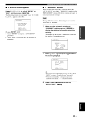
Optimizing the speaker setting for your speaker settings. WARNING(1) RESULT SP : 3/2/0.1 DIST: 3.2/3.5m LVL : -2/+2dB >SET CANCEL [ ]/[ ]:Up/Down [ENTER]:Enter 2 Press Gl / h repeatedly to select "RETRY" or "EXIT" and then press GENTER. Check the warning messages to correct your listening ...
Optimizing the speaker setting for your speaker settings. WARNING(1) RESULT SP : 3/2/0.1 DIST: 3.2/3.5m LVL : -2/+2dB >SET CANCEL [ ]/[ ]:Up/Down [ENTER]:Enter 2 Press Gl / h repeatedly to select "RETRY" or "EXIT" and then press GENTER. Check the warning messages to correct your listening ...

Owner's Manual
Page 32
... Movie View 3 Press the FSCENE (or ESCENE) button again to confirm the selection. As the initial factory setting, the following SCENE templates are assigned to the corresponding SCENE buttons, you may need to set the input source of the SCENE template on the remote control. SELECTING THE SCENE TEMPLATES Selecting the SCENE...
... Movie View 3 Press the FSCENE (or ESCENE) button again to confirm the selection. As the initial factory setting, the following SCENE templates are assigned to the corresponding SCENE buttons, you may need to set the input source of the SCENE template on the remote control. SELECTING THE SCENE TEMPLATES Selecting the SCENE...

