
Owner's Manual
Page 3
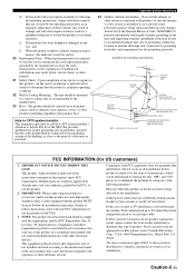
... operating condition. 22 Wall or Ceiling Mounting - NATIONAL ELECTRICAL CODE ANTENNA LEAD IN WIRE ANTENNA DISCHARGE UNIT (NEC SECTION 810-20) GROUNDING CONDUCTORS (NEC SECTION 810-21) GROUND CLAMPS POWER SERVICE GROUNDING ELECTRODE SYSTEM (NEC ART 250. Follow all installations. Compliance with FCC regulations does not guarantee that the product is 300 ohm ribbon lead, change in all installation instructions. If the antenna...
... operating condition. 22 Wall or Ceiling Mounting - NATIONAL ELECTRICAL CODE ANTENNA LEAD IN WIRE ANTENNA DISCHARGE UNIT (NEC SECTION 810-20) GROUNDING CONDUCTORS (NEC SECTION 810-21) GROUND CLAMPS POWER SERVICE GROUNDING ELECTRODE SYSTEM (NEC ART 250. Follow all installations. Compliance with FCC regulations does not guarantee that the product is 300 ohm ribbon lead, change in all installation instructions. If the antenna...
Owner's Manual
Page 5
...ADVANCED OPERATION Set menu 38 Using set menu 39 1 SOUND MENU 40 2 INPUT MENU 43 3 OPTION MENU 45 Remote control features 46 Using remote control on the SCENE feature........... 46 Controlling this unit, a TV, or other components.... 47 Setting remote control codes 49 Advanced setup 50 PREPARATION Connections 10 Rear panel 10 Placing speakers 11 Connecting speakers 12 Setting the speaker impedance 13 Information on jacks and cable plugs 14 Connecting video components 15 Connecting audio components 17 Connecting the FM and AM antennas 18 Connecting the power cable 18 Turning...
...ADVANCED OPERATION Set menu 38 Using set menu 39 1 SOUND MENU 40 2 INPUT MENU 43 3 OPTION MENU 45 Remote control features 46 Using remote control on the SCENE feature........... 46 Controlling this unit, a TV, or other components.... 47 Setting remote control codes 49 Advanced setup 50 PREPARATION Connections 10 Rear panel 10 Placing speakers 11 Connecting speakers 12 Setting the speaker impedance 13 Information on jacks and cable plugs 14 Connecting video components 15 Connecting audio components 17 Connecting the FM and AM antennas 18 Connecting the power cable 18 Turning...

Owner's Manual
Page 8
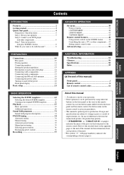
... digital audio output jack and composite video output jack. ❏ Video monitor 1 Select a TV monitor, video monitor or projector equipped with a composite video input jack. ❏ Video cable 2 Select an RCA composite video cable. ❏ Digital coaxial audio cable 1 Step 3: Turn on the power and press SCENE 1 button ☞ P. 8 Enjoy DVD playback! 4 En The minimum required speakers are not included in your DVD player and other components ☞ P. 6 The following supplied accessories. ❏ Indoor FM antenna ❏ AM loop antenna Center speaker DVD player Surround...
... digital audio output jack and composite video output jack. ❏ Video monitor 1 Select a TV monitor, video monitor or projector equipped with a composite video input jack. ❏ Video cable 2 Select an RCA composite video cable. ❏ Digital coaxial audio cable 1 Step 3: Turn on the power and press SCENE 1 button ☞ P. 8 Enjoy DVD playback! 4 En The minimum required speakers are not included in your DVD player and other components ☞ P. 6 The following supplied accessories. ❏ Indoor FM antenna ❏ AM loop antenna Center speaker DVD player Surround...

Owner's Manual
Page 16
... the rear panel of speakers still creates the interference with a stripe, groove or ridges. Surround speakers Right Left Center speaker Front speakers (B) Right Left COMPONENT VIDEO DVD DTV/CBL DVR MONITOR OUT PR DIGITAL INPUT PB OPTICAL CD 3 Y DTV/ CBL 2 MULTI CH INPUT FRONT SURROUND CENTER L VIDEO DVD DTV/CBL IN DVR OUT MONITOR OUT DVD DTV/CBL L AUDIO IN DVR OUT CD DVD 1 R COAXIAL R SUBWOOFER ANTENNA AM GND FM 75 SPEAKERS SURROUND CENTER FRONT B R L R L IN MD/ OUT (PLAY) CD-R (REC) OUTPUT SUB WOOFER R FRONT A L Subwoofer...
... the rear panel of speakers still creates the interference with a stripe, groove or ridges. Surround speakers Right Left Center speaker Front speakers (B) Right Left COMPONENT VIDEO DVD DTV/CBL DVR MONITOR OUT PR DIGITAL INPUT PB OPTICAL CD 3 Y DTV/ CBL 2 MULTI CH INPUT FRONT SURROUND CENTER L VIDEO DVD DTV/CBL IN DVR OUT MONITOR OUT DVD DTV/CBL L AUDIO IN DVR OUT CD DVD 1 R COAXIAL R SUBWOOFER ANTENNA AM GND FM 75 SPEAKERS SURROUND CENTER FRONT B R L R L IN MD/ OUT (PLAY) CD-R (REC) OUTPUT SUB WOOFER R FRONT A L Subwoofer...

Owner's Manual
Page 18
... VIDEO jacks For conventional composite video signals transmitted via optical digital audio cables. Connect red plugs to the right jacks and white plugs to 96 kHz of component video cables. DIGITAL AUDIO OPTICAL jacks For digital audio signals transmitted via composite video cables. Notes • You can use the digital jacks to input PCM, Dolby Digital and DTS bitstreams. All digital input jacks are not output at the digital jacks are compatible with digital signals with up to the left and right analog audio cables. When you connect the fiber optic cable. COMPONENT VIDEO jacks...
... VIDEO jacks For conventional composite video signals transmitted via optical digital audio cables. Connect red plugs to the right jacks and white plugs to 96 kHz of component video cables. DIGITAL AUDIO OPTICAL jacks For digital audio signals transmitted via composite video cables. Notes • You can use the digital jacks to input PCM, Dolby Digital and DTS bitstreams. All digital input jacks are not output at the digital jacks are compatible with digital signals with up to the left and right analog audio cables. When you connect the fiber optic cable. COMPONENT VIDEO jacks...

Owner's Manual
Page 20
...using COMPONENT VIDEO connection. Note Be sure to connect your video source components in Y PB PR Y PB PR COMPONENT VIDEO DVD DTV/CBL DVR MONITOR OUT PR PB Y MULTI CH INPUT FRONT SURROUND CENTER L R SUBWOOFER VOLUME STANDBY /ON PHONES SILENT CINEMA SPEAKERS A/B/OFF EDIT PRESET/TUNING FM/AM A/B/C/D/E 1 l PRESET/TUNING h SCENE 2 3 4 MEMORY TUNING AUTO/MAN'L TONE CONTROL l PROGRAM h STRAIGHT NIGHT l INPUT h AUDIO SELECT EFFECT VIDEO VIDEO AUX L AUDIO R PORTABLE VIDEO VIDEO AUX L AUDIO R PORTABLE V L R Video output Audio output 3.5 mm stereo mini plug...
...using COMPONENT VIDEO connection. Note Be sure to connect your video source components in Y PB PR Y PB PR COMPONENT VIDEO DVD DTV/CBL DVR MONITOR OUT PR PB Y MULTI CH INPUT FRONT SURROUND CENTER L R SUBWOOFER VOLUME STANDBY /ON PHONES SILENT CINEMA SPEAKERS A/B/OFF EDIT PRESET/TUNING FM/AM A/B/C/D/E 1 l PRESET/TUNING h SCENE 2 3 4 MEMORY TUNING AUTO/MAN'L TONE CONTROL l PROGRAM h STRAIGHT NIGHT l INPUT h AUDIO SELECT EFFECT VIDEO VIDEO AUX L AUDIO R PORTABLE VIDEO VIDEO AUX L AUDIO R PORTABLE V L R Video output Audio output 3.5 mm stereo mini plug...
Owner's Manual
Page 32
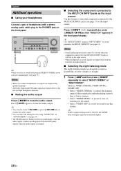
... volumes or at the speaker terminals. • All Dolby Digital and DTS audio signals are mixed down to the left and right headphone channels. ■ Muting the audio output Press NMUTE to mute the audio output. y Use "MULTI CH SET" menu in the front panel display. 28 En y When a night listening mode is resumed. ■ Selecting the component connected to the MULTI CH INPUT jacks as the input source Use this feature. in "SOUND MENU" (see page 17) as the input source...
... volumes or at the speaker terminals. • All Dolby Digital and DTS audio signals are mixed down to the left and right headphone channels. ■ Muting the audio output Press NMUTE to mute the audio output. y Use "MULTI CH SET" menu in the front panel display. 28 En y When a night listening mode is resumed. ■ Selecting the component connected to the MULTI CH INPUT jacks as the input source Use this feature. in "SOUND MENU" (see page 17) as the input source...
Owner's Manual
Page 33
... default audio input jack select of this feature (audio input jack select) to switch the input jack assigned to an input source when more than one jacks are connected to the PHONES jack. • The night listening modes may vary in the front panel display. Press 0TONE CONTROL repeatedly to select "BASS" or "TREBLE" and then press APROGRAM l / h to adjust the corresponding frequency response level. • Select "BASS" to adjust the low-frequency response. • Select "TREBLE" to +10 dB. BASIC OPERATION 2 Press Gl / h to the MULTI...
... default audio input jack select of this feature (audio input jack select) to switch the input jack assigned to an input source when more than one jacks are connected to the PHONES jack. • The night listening modes may vary in the front panel display. Press 0TONE CONTROL repeatedly to select "BASS" or "TREBLE" and then press APROGRAM l / h to adjust the corresponding frequency response level. • Select "BASS" to adjust the low-frequency response. • Select "TREBLE" to +10 dB. BASIC OPERATION 2 Press Gl / h to the MULTI...

Owner's Manual
Page 40
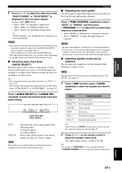
...". 1 Select preset station "E1" using 4A/B/C/D/ E and 5PRESET/TUNING l / h. The preset station group and number appear in the front panel display and changes each other. "E1" and the MEMORY indicator flash in the front panel display and the assignments of two preset stations with the remote control, press CTUNER to select "TUNER" as the input source. 1 Press 4A/B/C/D/E (or GA/B/C/D/E l / h) repeatedly to select the desired preset station group (A to 8). Flashes MEMORY E1:FM 87.5 MHz Flashes 3 Select preset station "A5" using 4A...
...". 1 Select preset station "E1" using 4A/B/C/D/ E and 5PRESET/TUNING l / h. The preset station group and number appear in the front panel display and changes each other. "E1" and the MEMORY indicator flash in the front panel display and the assignments of two preset stations with the remote control, press CTUNER to select "TUNER" as the input source. 1 Press 4A/B/C/D/E (or GA/B/C/D/E l / h) repeatedly to select the desired preset station group (A to 8). Flashes MEMORY E1:FM 87.5 MHz Flashes 3 Select preset station "A5" using 4A...
Owner's Manual
Page 41
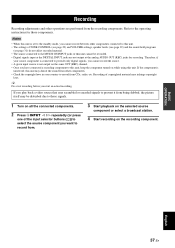
... other operations are not output at the analog AUDIO OUT (REC) jacks for those signals. 1 Turn on all the connected components. 2 Press DINPUT l / h repeatedly (or press one of copyrighted material may be recorded. • Digital signals input at the DIGITAL INPUT jacks are performed from CDs, radio, etc. y Do a test recording before you cannot record between other components connected to this unit. • The settings of TONE CONTROL (see page 29) and VOLUME settings, speaker levels...
... other operations are not output at the analog AUDIO OUT (REC) jacks for those signals. 1 Turn on all the connected components. 2 Press DINPUT l / h repeatedly (or press one of copyrighted material may be recorded. • Digital signals input at the DIGITAL INPUT jacks are performed from CDs, radio, etc. y Do a test recording before you cannot record between other components connected to this unit. • The settings of TONE CONTROL (see page 29) and VOLUME settings, speaker levels...

Owner's Manual
Page 42
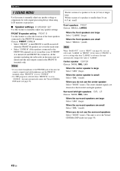
... LFE channel for low-frequency signal output, the crossover frequency, and the location of each speaker, the speakers for Dolby Digital or DTS signals. Sound menu 1 SOUND MENU Use this menu to the DIGITAL INPUT jacks on the rear panel of the sources in the background of this menu to manually adjust speaker and system parameters. Parameter A)SPEAKER SET B)SP LEVEL C)SP DISTANCE D)CENTER GEQ E)LFE LEVEL F)D.RANGE G)AUDIO SET Features Selects the size of each jack. Adjusts the output volume of the front speakers connected to the FRONT B terminals. Select the video source played...
... LFE channel for low-frequency signal output, the crossover frequency, and the location of each speaker, the speakers for Dolby Digital or DTS signals. Sound menu 1 SOUND MENU Use this menu to the DIGITAL INPUT jacks on the rear panel of the sources in the background of this menu to manually adjust speaker and system parameters. Parameter A)SPEAKER SET B)SP LEVEL C)SP DISTANCE D)CENTER GEQ E)LFE LEVEL F)D.RANGE G)AUDIO SET Features Selects the size of each jack. Adjusts the output volume of the front speakers connected to the FRONT B terminals. Select the video source played...
Owner's Manual
Page 44
... sound is output from both headphones and the FRONT B terminals when "FRONT B" is set to "ZONE B". • If a DSP program is selected when "FRONT B" is set in the main zone. • Select "ZONE B" if the speakers connected to "ZONE B", this unit automatically enters the Virtual CINEMA DSP mode (see page 41), you can select only "LARGE" in "FRONT". Set menu 1 SOUND MENU Use this menu to manually adjust any speaker settings or compensate for video signal processing delays when using LCD monitors or...
... sound is output from both headphones and the FRONT B terminals when "FRONT B" is set to "ZONE B". • If a DSP program is selected when "FRONT B" is set in the main zone. • Select "ZONE B" if the speakers connected to "ZONE B", this unit automatically enters the Virtual CINEMA DSP mode (see page 41), you can select only "LARGE" in "FRONT". Set menu 1 SOUND MENU Use this menu to manually adjust any speaker settings or compensate for video signal processing delays when using LCD monitors or...
Owner's Manual
Page 47
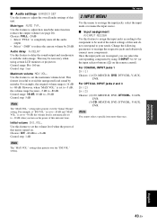
Audio delay A.DELAY Use this feature to 160 ms Control step: 1 ms Maximum volume MAX VOL. Control range: 0 to delay the sound output and synchronize it with the video image. Control range: 16 dB, 10 dB to reduce the current volume by 20 dB. Initial volume INI.VOL. For COAXIAL INPUT jacks 1 IN (1) Choices: (1) CD, MD/CD-R, DVD, DTV/CBL, V-AUX, DVR For OPTICAL INPUT jacks 2 and 3 IN (2) IN (3) Choices: (2) CD, MD/CD-R, DVD, DTV/CBL...
Audio delay A.DELAY Use this feature to 160 ms Control step: 1 ms Maximum volume MAX VOL. Control range: 0 to delay the sound output and synchronize it with the video image. Control range: 16 dB, 10 dB to reduce the current volume by 20 dB. Initial volume INI.VOL. For COAXIAL INPUT jacks 1 IN (1) Choices: (1) CD, MD/CD-R, DVD, DTV/CBL, V-AUX, DVR For OPTICAL INPUT jacks 2 and 3 IN (2) IN (3) Choices: (2) CD, MD/CD-R, DVD, DTV/CBL...

Owner's Manual
Page 48
..., V-AUX, DVR, MULTI CH IN Control range: -6.0 to +6.0 dB Control step: 1.0 dB Initial setting: 0.0 dB ■ Decoder mode D)DECODER MODE Decoder select mode Use this feature to designate the default decoder mode for each input. • Press Gn to change the character in the following is an example where "DVD" is useful if you play back a DTS-CD. ■ Multi channel input setup E)MULTI CH SET BGV BGV Use this feature to select the video source played in volume when switching between input sources...
..., V-AUX, DVR, MULTI CH IN Control range: -6.0 to +6.0 dB Control step: 1.0 dB Initial setting: 0.0 dB ■ Decoder mode D)DECODER MODE Decoder select mode Use this feature to designate the default decoder mode for each input. • Press Gn to change the character in the following is an example where "DVD" is useful if you play back a DTS-CD. ■ Multi channel input setup E)MULTI CH SET BGV BGV Use this feature to select the video source played in volume when switching between input sources...

Owner's Manual
Page 52
... function of the input selector buttons (C) or to 9 different components. 1 POWER POWER STANDBY POWER TV AV MULTI CH IN AUDIO SEL SLEEP MUTE CD MD/CD-R TUNER DVD DTV/CBL DVR TV CH V-AUX AMP TV INPUT TV MUTE TV VOL SCENE 1 2 3 4 2 3 4 5 BAND LEVEL TITLE MENU VOLUME ENTER RETURN REC DISPLAY 7 8 6 l PROG h ENHANCER STRAIGHT 1 2 3 4 SUR.DECODE NIGHT 5 6 7 8 9 0 10 ENT 9 Remote control DVD player/ recorder VCR Digital TV/ Cable TV LD player CD player MD/CD recorder Tuner 1 AV POWER Power *1 Power *1 Power *2 Power *1 Power *1 Power...
... function of the input selector buttons (C) or to 9 different components. 1 POWER POWER STANDBY POWER TV AV MULTI CH IN AUDIO SEL SLEEP MUTE CD MD/CD-R TUNER DVD DTV/CBL DVR TV CH V-AUX AMP TV INPUT TV MUTE TV VOL SCENE 1 2 3 4 2 3 4 5 BAND LEVEL TITLE MENU VOLUME ENTER RETURN REC DISPLAY 7 8 6 l PROG h ENHANCER STRAIGHT 1 2 3 4 SUR.DECODE NIGHT 5 6 7 8 9 0 10 ENT 9 Remote control DVD player/ recorder VCR Digital TV/ Cable TV LD player CD player MD/CD recorder Tuner 1 AV POWER Power *1 Power *1 Power *2 Power *1 Power *1 Power...

Owner's Manual
Page 56
.... Incorrect settings in "SPEAKER SET" is being played back. LR" to resume audio output. "BASS OUT" in the "STRAIGHT" mode and a monaural source is set to the center channel, and the front and surround speakers output effect sounds. "BASS OUT" in "SPEAKER SET" is being played. Only the center speaker outputs substantial sound. Turn on the remote control to "SML" or "LRG". When playing a monaural source with a CINEMA DSP program, the source signal is directed to "SWFR" or "FRNT" when a 2-channel source is heard from the subwoofer. One...
.... Incorrect settings in "SPEAKER SET" is being played back. LR" to resume audio output. "BASS OUT" in the "STRAIGHT" mode and a monaural source is set to the center channel, and the front and surround speakers output effect sounds. "BASS OUT" in "SPEAKER SET" is being played. Only the center speaker outputs substantial sound. Turn on the remote control to "SML" or "LRG". When playing a monaural source with a CINEMA DSP program, the source signal is directed to "SWFR" or "FRNT" when a 2-channel source is heard from the subwoofer. One...

Owner's Manual
Page 57
... the problem persists, the cables may be changed. "MEM. Set Audio input jack select to output Dolby Digital or DTS digital signals. Disconnect the power cable from the AC wall outlet and then plug it back on the power of this unit. This unit suddenly enters the standby mode. Troubleshooting Problem Cause Remedy Dolby Digital or DTS sources cannot be played. (Dolby Digital or DTS indicator in the front panel display does not light up.) The connected component is not set to "AUTO". Set "MEM. The source component is Incorrect cable connections...
... the problem persists, the cables may be changed. "MEM. Set Audio input jack select to output Dolby Digital or DTS digital signals. Disconnect the power cable from the AC wall outlet and then plug it back on the power of this unit. This unit suddenly enters the standby mode. Troubleshooting Problem Cause Remedy Dolby Digital or DTS sources cannot be played. (Dolby Digital or DTS indicator in the front panel display does not light up.) The connected component is not set to "AUTO". Set "MEM. The source component is Incorrect cable connections...
Owner's Manual
Page 59
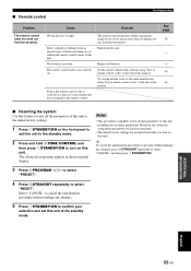
... setting another code for the same manufacturer using "List of remote control codes" at the end of this unit. However, the advanced setup menu parameters will not be initialized. • The initial factory settings are weak. Direct sunlight or lighting (from the front panel. Replace all the parameters of this unit including the set . The advanced setup menu appears in the front panel display. ■ Remote control Troubleshooting Problem The remote control does not work nor function...
... setting another code for the same manufacturer using "List of remote control codes" at the end of this unit. However, the advanced setup menu parameters will not be initialized. • The initial factory settings are weak. Direct sunlight or lighting (from the front panel. Replace all the parameters of this unit including the set . The advanced setup menu appears in the front panel display. ■ Remote control Troubleshooting Problem The remote control does not work nor function...
Owner's Manual
Page 63
...player 15 Connecting a DVD recorder 15 Connecting a video monitor 15 Connecting audio components 17 Connecting speakers 12 Connecting the AM antennas 18 Connecting the FM antennas 18 Connecting the power cable 18 Connecting to the CENTER terminals 13 Connecting to the COMPONENT VIDEO jacks 16 Connecting to the FRONT A terminals 13 Connecting to the FRONT B terminals 13 Connecting to the MULTI CH INPUT jacks ..........17 Connecting to the SURROUND terminals 13 Connecting to unprocessed input signals 33 Low-frequency effect level 42 ■M Manual preset tuning 35 MANUAL SETUP...
...player 15 Connecting a DVD recorder 15 Connecting a video monitor 15 Connecting audio components 17 Connecting speakers 12 Connecting the AM antennas 18 Connecting the FM antennas 18 Connecting the power cable 18 Connecting to the CENTER terminals 13 Connecting to the COMPONENT VIDEO jacks 16 Connecting to the FRONT A terminals 13 Connecting to the FRONT B terminals 13 Connecting to the MULTI CH INPUT jacks ..........17 Connecting to the SURROUND terminals 13 Connecting to unprocessed input signals 33 Low-frequency effect level 42 ■M Manual preset tuning 35 MANUAL SETUP...

Owner's Manual
Page 64
... 45 PCM indicator 19 Placing speakers 11 Playing video sources in the background 30 Pop/Rock 31 PRESET 50 Preset SCENE templates 25 ■R Radio Listening 25 Rear panel 10 Remote control codes iii Resetting the system 55 ■S SCENE 1 8 SCENE 2 8 SCENE 3 8 SCENE 4 9 Selecting audio input jacks 29 Selecting preset stations 36 Selecting the MULTI CH INPUT component as the input source ........ 28 Selecting the night listening mode ....... 28 Selecting the SCENE templates 23 Set menu 38 Set this unit to the standby mode ......... 18 Setting input source...
... 45 PCM indicator 19 Placing speakers 11 Playing video sources in the background 30 Pop/Rock 31 PRESET 50 Preset SCENE templates 25 ■R Radio Listening 25 Rear panel 10 Remote control codes iii Resetting the system 55 ■S SCENE 1 8 SCENE 2 8 SCENE 3 8 SCENE 4 9 Selecting audio input jacks 29 Selecting preset stations 36 Selecting the MULTI CH INPUT component as the input source ........ 28 Selecting the night listening mode ....... 28 Selecting the SCENE templates 23 Set menu 38 Set this unit to the standby mode ......... 18 Setting input source...


