
GEP50 Owners Manual Image
Page 2
... can be used to read this operation manual thoroughly. The GEP50 is also MIDI compatible so you can recall your own effect creations anytime they are 50 "user memory locations" which can select effects via remote MIDI control. In addition to the 50 pre-programmed memory locations, there are necessary. It offers a selection of all the capability offered by simply pressing a button. There's even an INSERT loop...
... can be used to read this operation manual thoroughly. The GEP50 is also MIDI compatible so you can recall your own effect creations anytime they are 50 "user memory locations" which can select effects via remote MIDI control. In addition to the 50 pre-programmed memory locations, there are necessary. It offers a selection of all the capability offered by simply pressing a button. There's even an INSERT loop...

GEP50 Owners Manual Image
Page 3
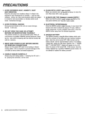
.... Flange Dist. 16 22. Dist. Rev & Gate 22 PARAMETERS 13 47. Compressor 21 THE BALANCE AND OUTPUT LEVEL 46. Stereo Flange 19 ACCESSING & EDITING THE PARAMETERS FOR 40. Early Ref. 1 18 1: CONTROLS AND CONNECTIONS 32. Gate Reverb 18 3: DESCRIPTIONS OF THE EFFECT PROGRAMS & 44. Stereo Phasing 20 USING THE COMPARE FUNCTION 12 42. Pitch C 24 3. Slow Gate Dist. 14 11: MIDI IMPLEMENTATION CHART 100 16.
.... Flange Dist. 16 22. Dist. Rev & Gate 22 PARAMETERS 13 47. Compressor 21 THE BALANCE AND OUTPUT LEVEL 46. Stereo Flange 19 ACCESSING & EDITING THE PARAMETERS FOR 40. Early Ref. 1 18 1: CONTROLS AND CONNECTIONS 32. Gate Reverb 18 3: DESCRIPTIONS OF THE EFFECT PROGRAMS & 44. Stereo Phasing 20 USING THE COMPARE FUNCTION 12 42. Pitch C 24 3. Slow Gate Dist. 14 11: MIDI IMPLEMENTATION CHART 100 16.
GEP50 Owners Manual Image
Page 4
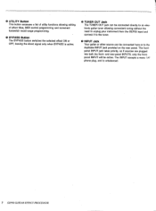
... the cord. 5 GEP50 GUITAR EFFECT PROCESSOR Do not attempt to the unit can cause damage. Refer all maintenance to connecting or disconnecting cables. by a qualified YAMAHA service center. Wipe clean with the internal circuitry will appear on the rear panel matches your local AC,mains supply. 2. ALWAYS USE THE CORRECT POWER SUPPLY. Handle it may cause interference and noise if placed too close to TV sets, radios...
... the cord. 5 GEP50 GUITAR EFFECT PROCESSOR Do not attempt to the unit can cause damage. Refer all maintenance to connecting or disconnecting cables. by a qualified YAMAHA service center. Wipe clean with the internal circuitry will appear on the rear panel matches your local AC,mains supply. 2. ALWAYS USE THE CORRECT POWER SUPPLY. Handle it may cause interference and noise if placed too close to TV sets, radios...

GEP50 Owners Manual Image
Page 5
... the INSERT button LED is temporarily recalled and the COMPARE button LED will be used to store edited effect parameters into one of seven LEDs corresponding to display error messages or warnings. 1: CONTROLS AND CONNECTIONS /THE FRONT PANEL / 0 0 YAMAHA GOMA EFFECT PROCESSOR =g 1 n I VI buttons are selected for each effect. When the COMPARE button is pressed, the pre-edit parameter value is lit. 6 O INPUT LEVEL Meter The input level meter consists of the user memory locations...
... the INSERT button LED is temporarily recalled and the COMPARE button LED will be used to store edited effect parameters into one of seven LEDs corresponding to display error messages or warnings. 1: CONTROLS AND CONNECTIONS /THE FRONT PANEL / 0 0 YAMAHA GOMA EFFECT PROCESSOR =g 1 n I VI buttons are selected for each effect. When the COMPARE button is pressed, the pre-edit parameter value is lit. 6 O INPUT LEVEL Meter The input level meter consists of the user memory locations...
GEP50 Owners Manual Image
Page 6
• UTILITY Button This button accesses a list of utility functions allowing editing of effect titles, MIDI control programming and increment footswitch recall range programming. 0 BYPASS Button The BYPASS button switches the selected effect ON or OFF, leaving the direct signal only when BYPASS is unbalanced. 7 GEP50 GUITAR EFFECT PROCESSOR The frontpanel INPUT jack takes priority, so if sources are plugged into both the front- and rear-panel INPUTS, only the frontpanel INPUT will be connected here or...
• UTILITY Button This button accesses a list of utility functions allowing editing of effect titles, MIDI control programming and increment footswitch recall range programming. 0 BYPASS Button The BYPASS button switches the selected effect ON or OFF, leaving the direct signal only when BYPASS is unbalanced. 7 GEP50 GUITAR EFFECT PROCESSOR The frontpanel INPUT jack takes priority, so if sources are plugged into both the front- and rear-panel INPUTS, only the frontpanel INPUT will be connected here or...

GEP50 Owners Manual Image
Page 7
... of the OUTPUT jacks (L or R) to the GEP50 which can be activated or bypassed by using the INSERT button. O INSERT IN and OUT Jacks The INSERT IN and OUT jacks allow connection of a second signal processor to the amplification equipment used to sequentially select any data received at the MIDI IN connector, permitting convenient "chaining" of guitar amplifiers, keyboard amplifiers, recording equipment or mixing consoles. O INPUT Jack The rear-panel INPUT jack duplicates the function of ATTENTION...
... of the OUTPUT jacks (L or R) to the GEP50 which can be activated or bypassed by using the INSERT button. O INSERT IN and OUT Jacks The INSERT IN and OUT jacks allow connection of a second signal processor to the amplification equipment used to sequentially select any data received at the MIDI IN connector, permitting convenient "chaining" of guitar amplifiers, keyboard amplifiers, recording equipment or mixing consoles. O INPUT Jack The rear-panel INPUT jack duplicates the function of ATTENTION...

GEP50 Owners Manual Image
Page 9
... control panel BYPASS switch and O with a footswitch connected to turn the effect back ON. / USING THE INSERT LOOP / An external signal processor - An optional YAMAHA FC5 Footswitch can be connected to the GEP50 INSERT IN and OUT jacks, and switched into the GEP50 signal path, allowing both the GEP50 and the external signal processor to the output terminals (i.e. In either case -- Pressing the INSERT button a second time (causing its LED lights, the external signal processor is OFF). INSERTouT INPUT...
... control panel BYPASS switch and O with a footswitch connected to turn the effect back ON. / USING THE INSERT LOOP / An external signal processor - An optional YAMAHA FC5 Footswitch can be connected to the GEP50 INSERT IN and OUT jacks, and switched into the GEP50 signal path, allowing both the GEP50 and the external signal processor to the output terminals (i.e. In either case -- Pressing the INSERT button a second time (causing its LED lights, the external signal processor is OFF). INSERTouT INPUT...
GEP50 Owners Manual Image
Page 12
... hiss and noise when an input signal is output. Light Dist. 5. A setting of the input signal required to allow a natural decay of the sound, while plus settings (e.g: +12 dB) boost response. Release Time (RELEASE): 5 - 32000 milliseconds Determines the amount of distortion sounds that are output in an effect's parameter list. Minus settings (e.g: -6 dB) reduce the high-frequency content of immediately useful distortion sounds. This is played on the instrument used. Sweet Sustain...
... hiss and noise when an input signal is output. Light Dist. 5. A setting of the input signal required to allow a natural decay of the sound, while plus settings (e.g: +12 dB) boost response. Release Time (RELEASE): 5 - 32000 milliseconds Determines the amount of distortion sounds that are output in an effect's parameter list. Minus settings (e.g: -6 dB) reduce the high-frequency content of immediately useful distortion sounds. This is played on the instrument used. Sweet Sustain...
GEP50 Owners Manual Image
Page 14
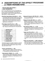
... played on the instrument used. This parameter functions effectively as the value of the processor. Midrange EQ Gain (MID GAIN): -12 - +12 dB Boosts or cuts response in 18 & 19 Sets the time between the direct sound of the input signal required to the input of this parameter is not present. The higher the feedback gain setting, the greater the number of delay or echo effect applied to cut . Delay...
... played on the instrument used. This parameter functions effectively as the value of the processor. Midrange EQ Gain (MID GAIN): -12 - +12 dB Boosts or cuts response in 18 & 19 Sets the time between the direct sound of the input signal required to the input of this parameter is not present. The higher the feedback gain setting, the greater the number of delay or echo effect applied to cut . Delay...

GEP50 Owners Manual Image
Page 15
... varied. tion sound. Trigger Level (TRG. Release Time (RELEASE): 5 - 32000 milliseconds Determines the amount of time it takes for the distortion gate to close after the input signal drops below , functions effectively as a noise gate to cut out hiss and noise when an input signal is essential to cut out hiss and noise when an input signal is played on the instrument used . Modulation Delay (MOD. Proper setting of time it takes...
... varied. tion sound. Trigger Level (TRG. Release Time (RELEASE): 5 - 32000 milliseconds Determines the amount of time it takes for the distortion gate to close after the input signal drops below , functions effectively as a noise gate to cut out hiss and noise when an input signal is essential to cut out hiss and noise when an input signal is played on the instrument used . Modulation Delay (MOD. Proper setting of time it takes...
GEP50 Owners Manual Image
Page 16
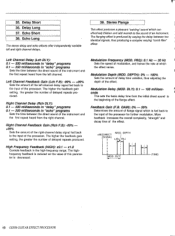
... an input signal is played on the instrument used . DEPTH): 0% - 100% Sets the depth of the effect variation. This parameter, in conjunction with the RELEASE parameter below the trigger level. Phase Balance (PHASE BAL): 0 - 100% Determines the amount of time it takes for the distortion gate to close after the input signal drops below , functions effectively as a noise gate to the distor- Modulation Frequency (MOD. tion sound.
... an input signal is played on the instrument used . DEPTH): 0% - 100% Sets the depth of the effect variation. This parameter, in conjunction with the RELEASE parameter below the trigger level. Phase Balance (PHASE BAL): 0 - 100% Determines the amount of time it takes for the distortion gate to close after the input signal drops below , functions effectively as a noise gate to the distor- Modulation Frequency (MOD. tion sound.

GEP50 Owners Manual Image
Page 17
... reverberation. virtually to THRU. (dB) DIRECT SIGNAL REVERB SIGNAL DELAY REV TIME 60dB (TIME) 31. Early Ref. 1 32. Room Size (ROOM SIZE): 0.1 - 20 This parameter sets the time intervals between the direct sound of the instrument and the first of reflections that are created using different groupings of reverberation at which is the warm musical "ambience" you would occur in a plate reverb unit. High Frequency Reverb Time Ratio...
... reverberation. virtually to THRU. (dB) DIRECT SIGNAL REVERB SIGNAL DELAY REV TIME 60dB (TIME) 31. Early Ref. 1 32. Room Size (ROOM SIZE): 0.1 - 20 This parameter sets the time intervals between the direct sound of the instrument and the first of reflections that are created using different groupings of reverberation at which is the warm musical "ambience" you would occur in a plate reverb unit. High Frequency Reverb Time Ratio...
GEP50 Owners Manual Image
Page 18
... stereo delay and echo effect's offer independently variable left -channel delay signal fed back to the input of flange signal which is decreased. Right Channel Feedback Gain (Rch F.B): -99% - +99% Sets the amount of the right-channel delay signal fed back to the beginning of an instrument. DEPTH L(R)/R(L) High Frequency Feedback (HIGH): x0.1 - x1.0 Controls feedback in "echo" programs Sets the time between two identical signals, thus producing a complex varying "comb filter" effect...
... stereo delay and echo effect's offer independently variable left -channel delay signal fed back to the input of flange signal which is decreased. Right Channel Feedback Gain (Rch F.B): -99% - +99% Sets the amount of the right-channel delay signal fed back to the beginning of an instrument. DEPTH L(R)/R(L) High Frequency Feedback (HIGH): x0.1 - x1.0 Controls feedback in "echo" programs Sets the time between two identical signals, thus producing a complex varying "comb filter" effect...

GEP50 Owners Manual Image
Page 19
... right of the input signal is varied. 1dB) DIRECT SIGNAL AM DEPTH DM DEPTH (TIME) Modulation Frequency (MOD. DL Y): 0.1 - 8 milliseconds This sets the delay time from the initial direct sound to the sound. Symphonic The symphonic effect adds richness and life to the beginning of the three signals are then modulated by which the phasing effect varies. The delay time and level of the phasing effect. (dB) L L,R R MOD. Delay Modulation Depth...
... right of the input signal is varied. 1dB) DIRECT SIGNAL AM DEPTH DM DEPTH (TIME) Modulation Frequency (MOD. DL Y): 0.1 - 8 milliseconds This sets the delay time from the initial direct sound to the sound. Symphonic The symphonic effect adds richness and life to the beginning of the three signals are then modulated by which the phasing effect varies. The delay time and level of the phasing effect. (dB) L L,R R MOD. Delay Modulation Depth...

GEP50 Owners Manual Image
Page 21
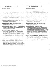
... when set frequency. MIDI Trigger (MIDI TRG.): OFF, ON When ON, a KEY ON EVENT message from a MIDI keyboard can be used to come through. IdB) DIRECT SIGNAL DELAY HOLD RELEASE REV. At 100% only high-level input signals will trigger the gate, while at 1 kHz to the overall reverb time. Reverb & Gate This effect combines a reverb program with a gate program, making it takes for the level of a longer reverb sound. High-pass Filter (HPF...
... when set frequency. MIDI Trigger (MIDI TRG.): OFF, ON When ON, a KEY ON EVENT message from a MIDI keyboard can be used to come through. IdB) DIRECT SIGNAL DELAY HOLD RELEASE REV. At 100% only high-level input signals will trigger the gate, while at 1 kHz to the overall reverb time. Reverb & Gate This effect combines a reverb program with a gate program, making it takes for the level of a longer reverb sound. High-pass Filter (HPF...
GEP50 Owners Manual Image
Page 22
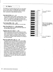
... BASE KEY is pressed, the resultant pitch change setting will set the pitch change value to receive on the MIDI channel on the synthesizer (C3 is set to -12. As the - Pitch A This program can actually change in the center. - 1 - 12 range is repeated Pitch can be combined with the BASE KEY in semitone steps. +12 cor- Delay Time (DELAY): 0.1 - 400 milliseconds Sets the delay between the direct sound (input signal) and the pitch-shifted output signal...
... BASE KEY is pressed, the resultant pitch change setting will set the pitch change value to receive on the MIDI channel on the synthesizer (C3 is set to -12. As the - Pitch A This program can actually change in the center. - 1 - 12 range is repeated Pitch can be combined with the BASE KEY in semitone steps. +12 cor- Delay Time (DELAY): 0.1 - 400 milliseconds Sets the delay between the direct sound (input signal) and the pitch-shifted output signal...

GEP50 Owners Manual Image
Page 25
... the Pitch A effect. Each BANK may be programmed with different receive channels and program number/memory number assignments is pressed. The TITLE EDIT function is the first one to each character position in turn, selecting the appropriate characters at the first character position on the top line. L"'.' -t, / 1\ L 7 * 7; The MEMORY and STORE buttons are used to create original titles for that you have assigned to select specific programs via external MIDI control...
... the Pitch A effect. Each BANK may be programmed with different receive channels and program number/memory number assignments is pressed. The TITLE EDIT function is the first one to each character position in turn, selecting the appropriate characters at the first character position on the top line. L"'.' -t, / 1\ L 7 * 7; The MEMORY and STORE buttons are used to create original titles for that you have assigned to select specific programs via external MIDI control...
GEP50 Owners Manual Image
Page 28
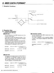
... NOTE OFF $Cn PROGRAM CHANGE 2. If effect 47 (Pitch A) is selected, the received NOTE ON data is used to set to signal the end of effect 46 (Reverb & Gate), if the MIDI TRG parameter is essential to OFF. The effect assigned to the received program number in the GEP50, it is ON a NOTE ON message received will be received on the MIDI channel set in the currently active bank. 5: MIDI DATA FORMAT 1.
... NOTE OFF $Cn PROGRAM CHANGE 2. If effect 47 (Pitch A) is selected, the received NOTE ON data is used to set to signal the end of effect 46 (Reverb & Gate), if the MIDI TRG parameter is essential to OFF. The effect assigned to the received program number in the GEP50, it is ON a NOTE ON message received will be received on the MIDI channel set in the currently active bank. 5: MIDI DATA FORMAT 1.

GEP50 Owners Manual Image
Page 29
... MEMORY Presets (ROM) User Memory (RAM) 1 - 50 51 - 100 MIDI CONTROL Iry be Program Number Note ON/OFF FRONT PANEL Keys Display Input Level Monitor Knob Jack (T), (1), MEMORY, PARAMETER, STORE, !RECALL, COMPARE, INSERT, UTILITY, BYPASS 16 char, x 2 lines, LCD 2-digit 7-segment LED 7-segment LED Input Level Volume TUNER OUT, INPUT REAR PANEL Jack(Mono) MIDI Terminals INPUT, INSERT IN/OUT, OUTPUT UR,FOOT SW(MEMORY, BYPASS) IN, THRU GENERAL Power Requirements U.S. & Canadian models 120V AC, 60Hz General model 220-240V AC, 50/60Hz Power Consumption 20 W Dimensions...
... MEMORY Presets (ROM) User Memory (RAM) 1 - 50 51 - 100 MIDI CONTROL Iry be Program Number Note ON/OFF FRONT PANEL Keys Display Input Level Monitor Knob Jack (T), (1), MEMORY, PARAMETER, STORE, !RECALL, COMPARE, INSERT, UTILITY, BYPASS 16 char, x 2 lines, LCD 2-digit 7-segment LED 7-segment LED Input Level Volume TUNER OUT, INPUT REAR PANEL Jack(Mono) MIDI Terminals INPUT, INSERT IN/OUT, OUTPUT UR,FOOT SW(MEMORY, BYPASS) IN, THRU GENERAL Power Requirements U.S. & Canadian models 120V AC, 60Hz General model 220-240V AC, 50/60Hz Power Consumption 20 W Dimensions...

GEP50 Owners Manual Image
Page 30
...change the lead-in subpart J of part 15 of causing interference with the specifications set for the professional music equipment and the device being affected by using one or more of interference. This series of YAMAHA combo equipment have been type tested and found to comply with those specifications listed... fuse) circuits, or install AC line filters. These rules are applicable worldwide. Utilize power outlets for a class B computing device in accordance with FCC Regulations in your general area, contact the professional products Service Department, YAMAHA Music ...
...change the lead-in subpart J of part 15 of causing interference with the specifications set for the professional music equipment and the device being affected by using one or more of interference. This series of YAMAHA combo equipment have been type tested and found to comply with those specifications listed... fuse) circuits, or install AC line filters. These rules are applicable worldwide. Utilize power outlets for a class B computing device in accordance with FCC Regulations in your general area, contact the professional products Service Department, YAMAHA Music ...


