

Owner's Manual
Page 1
E Owner's Manual Keep This Manual For Future Reference.
E Owner's Manual Keep This Manual For Future Reference.
Owner's Manual
Page 2
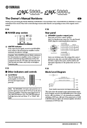
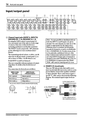
...the internal power amplifier section is +11dB (LIMITER indicator lights), the internal amplifier will deliver 100W into 4Ω. 1 EMX5000-20/EMX5000-12 Jacks 1 are 1/4"phone jacks. Neutrik NL4FC CHANNEL B 1+ B+ 1- B- Please refer to connect speakers. The LIMITER indicator ... Meter "0"), the internal power amplifier will deliver a maximum of the EMX5000-20, EMX5000-12 owner's manual have been revised. Use only Neutrik NL4FC plugs for purchasing the Yamaha EMX5000-20/EMX5000-12 Powered Mixer. Parts of 500W into a 4Ω load. Jacks 2 are ...
...the internal power amplifier section is +11dB (LIMITER indicator lights), the internal amplifier will deliver 100W into 4Ω. 1 EMX5000-20/EMX5000-12 Jacks 1 are 1/4"phone jacks. Neutrik NL4FC CHANNEL B 1+ B+ 1- B- Please refer to connect speakers. The LIMITER indicator ... Meter "0"), the internal power amplifier will deliver a maximum of the EMX5000-20, EMX5000-12 owner's manual have been revised. Use only Neutrik NL4FC plugs for purchasing the Yamaha EMX5000-20/EMX5000-12 Powered Mixer. Parts of 500W into a 4Ω load. Jacks 2 are ...
Owner's Manual
Page 4
... the antenna. Compliance with FCC regulations does not guarantee that may not correspond with the requirements listed in harmful interference with this manual, meets FCC requirements. REFER SERVICING TO QUALIFIED SERVICE PERSONNEL. The wire which is marked with the letter L or coloured RED... devices. If these requirements provides a reasonable level of assurance that the connection can not locate the appropriate retailer, please contact Yamaha Corporation of America, Electronic Service Division, 6600 Orangethorpe Ave, Buena Park, CA 90620 The above warning is located on the ...
... the antenna. Compliance with FCC regulations does not guarantee that may not correspond with the requirements listed in harmful interference with this manual, meets FCC requirements. REFER SERVICING TO QUALIFIED SERVICE PERSONNEL. The wire which is marked with the letter L or coloured RED... devices. If these requirements provides a reasonable level of assurance that the connection can not locate the appropriate retailer, please contact Yamaha Corporation of America, Electronic Service Division, 6600 Orangethorpe Ave, Buena Park, CA 90620 The above warning is located on the ...
Owner's Manual
Page 5
...shock hazard. • This unit has ventilation holes at the rear to prevent the internal temperature rising too high. Using the unit in this Owner's Manual or as when going on the power to this unit. Locations exposed to oil splashes or steam, such as a wobbly table or slope. - ... on top of the power cord. Doing so is a fire and electrical shock hazard. • Do not remove the unit's cover. EMX5000-20/EMX5000-12-Owner's Manual If you can easily reach the power plug. If you notice any abnormality, such as possible, and unplug the power cable plug from the...
...shock hazard. • This unit has ventilation holes at the rear to prevent the internal temperature rising too high. Using the unit in this Owner's Manual or as when going on the power to this unit. Locations exposed to oil splashes or steam, such as a wobbly table or slope. - ... on top of the power cord. Doing so is a fire and electrical shock hazard. • Do not remove the unit's cover. EMX5000-20/EMX5000-12-Owner's Manual If you can easily reach the power plug. If you notice any abnormality, such as possible, and unplug the power cable plug from the...
Owner's Manual
Page 6
... wired as follows: sleeve: ground, tip: send, and ring: return. Volume level setting • Do not set all equalizer controls and faders to maximum. EMX5000-20/EMX5000-12-Owner's Manual FOR CORRECT OPERATION - Doing so may cause oscillation depending on the condition of this unit may induce noise. If noise occurs, relocate the affected...
... wired as follows: sleeve: ground, tip: send, and ring: return. Volume level setting • Do not set all equalizer controls and faders to maximum. EMX5000-20/EMX5000-12-Owner's Manual FOR CORRECT OPERATION - Doing so may cause oscillation depending on the condition of this unit may induce noise. If noise occurs, relocate the affected...
Owner's Manual
Page 7
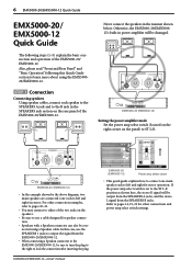
... optional rack mount kit 32 Block/Level Diagram 33 EMX5000-20/EMX5000-12-Owner's Manual You can be used to add reverb or ambience to the acclaimed Yamaha SPX series of multi-effect units. In order to take full advantage of the EMX5000-20/EMX5000-12 and enjoy long, trouble-free performance, please read... this owner's manual carefully, and keep it in energy cost and to less...
... optional rack mount kit 32 Block/Level Diagram 33 EMX5000-20/EMX5000-12-Owner's Manual You can be used to add reverb or ambience to the acclaimed Yamaha SPX series of multi-effect units. In order to take full advantage of the EMX5000-20/EMX5000-12 and enjoy long, trouble-free performance, please read... this owner's manual carefully, and keep it in energy cost and to less...
Owner's Manual
Page 8
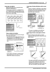
... the SPEAKERS A jacks, and the stereo L signal from the SPEAKERS B jacks. In this Quick Guide section to learn more about using a Speakon cable. EMX5000-20/EMX5000-12-Owner's Manual EMX5000-20 (EMX5000-12) Power amp select switch • This quick guide explains how to connect one each to left and right for other connection examples, refer to...
... the SPEAKERS A jacks, and the stereo L signal from the SPEAKERS B jacks. In this Quick Guide section to learn more about using a Speakon cable. EMX5000-20/EMX5000-12-Owner's Manual EMX5000-20 (EMX5000-12) Power amp select switch • This quick guide explains how to connect one each to left and right for other connection examples, refer to...
Owner's Manual
Page 9
Connect mics to the 2TR IN jacks. EMX5000-20/EMX5000-12-Owner's Manual EMX5000-20 (EMX5000-12) Microphone EMX5000-20 (EMX5000-12) Using a condenser microphone Turn on the PHANTOM switch (located in the upper center corner on the panel). • The PHANTOM switch supplies phantom power to...has an XLR plug, or the INPUT B jacks if the mic has a phone plug. Refer to the operation manual of the corresponding device for the same channel at once (EMX5000-20: 1-8 and 9- 16, EMX5000-12: 1-8), so mics other than condenser mics must be connected to the unit is turned off to the INPUT B ...
Connect mics to the 2TR IN jacks. EMX5000-20/EMX5000-12-Owner's Manual EMX5000-20 (EMX5000-12) Microphone EMX5000-20 (EMX5000-12) Using a condenser microphone Turn on the PHANTOM switch (located in the upper center corner on the panel). • The PHANTOM switch supplies phantom power to...has an XLR plug, or the INPUT B jacks if the mic has a phone plug. Refer to the operation manual of the corresponding device for the same channel at once (EMX5000-20: 1-8 and 9- 16, EMX5000-12: 1-8), so mics other than condenser mics must be connected to the unit is turned off to the INPUT B ...
Owner's Manual
Page 10
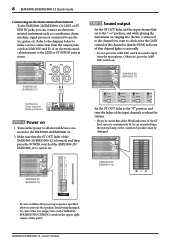
...EMX5000-20/EMX5000-12-Owner's Manual EMX5000-20 (EMX5000-12) EMX5000-20 (EMX5000-12) Synthesizer, Drum machine, Guitar processor STEP 2 Power on 1 Turn on the YAMAHA SPEAKER PROCESSING switch in stereo. Refer to the diagram below to make a stereo connection from being damaged. • To correct the low range, turn it on . EMX5000-20 (EMX5000-12) EMX5000-20 (EMX5000-12... signal processor connected to an electric guitar, etc. 8 EMX5000-20/EMX5000-12 Quick Guide Connecting an electronic musical instrument To the EMX5000-20/EMX5000-12's LINE or ST SUB IN jacks, you want to check...
...EMX5000-20/EMX5000-12-Owner's Manual EMX5000-20 (EMX5000-12) EMX5000-20 (EMX5000-12) Synthesizer, Drum machine, Guitar processor STEP 2 Power on 1 Turn on the YAMAHA SPEAKER PROCESSING switch in stereo. Refer to the diagram below to make a stereo connection from being damaged. • To correct the low range, turn it on . EMX5000-20 (EMX5000-12) EMX5000-20 (EMX5000-12... signal processor connected to an electric guitar, etc. 8 EMX5000-20/EMX5000-12 Quick Guide Connecting an electronic musical instrument To the EMX5000-20/EMX5000-12's LINE or ST SUB IN jacks, you want to check...
Owner's Manual
Page 11
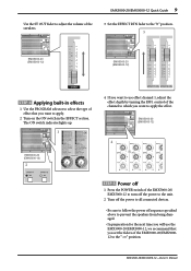
..."0" position. 3 EMX5000-20 (EMX5000-12) EMX5000-20 (EMX5000-12) STEP 4 Applying built-in the EFFECT section. The ON switch indicator lights up. 1 EMX5000-20 (EMX5000-12) 2 4 If you want to use the EMX5000-20/EMX5000-12, we recommend that you want to the "-∞" position. EMX5000-20 (EMX5000-12) 4 STEP 5 Power off 1 Press the POWER switch of the EMX5000-20/ EMX5000-12 to turn off ... switch in effects 1 Use the PROGRAM selector to select the type of the channel to which you set the faders of the EMX5000-20/EMX500012 to apply the effect. EMX5000-20/EMX5000-12-Owner's Manual
..."0" position. 3 EMX5000-20 (EMX5000-12) EMX5000-20 (EMX5000-12) STEP 4 Applying built-in the EFFECT section. The ON switch indicator lights up. 1 EMX5000-20 (EMX5000-12) 2 4 If you want to use the EMX5000-20/EMX5000-12, we recommend that you want to the "-∞" position. EMX5000-20 (EMX5000-12) 4 STEP 5 Power off 1 Press the POWER switch of the EMX5000-20/ EMX5000-12 to turn off ... switch in effects 1 Use the PROGRAM selector to select the type of the channel to which you set the faders of the EMX5000-20/EMX500012 to apply the effect. EMX5000-20/EMX5000-12-Owner's Manual
Owner's Manual
Page 12
... as follows: HIGH: 10kHz, ±15 dB, shelving type MID: 250Hz-5kHz, ±15 dB, peaking type LOW: 100Hz, ±15 dB, shelving type EMX5000-20/EMX5000-12-Owner's Manual The high-pass filter is on when the switch is pressed inward, and the frequency region below 80 Hz will have a flat...
... as follows: HIGH: 10kHz, ±15 dB, shelving type MID: 250Hz-5kHz, ±15 dB, peaking type LOW: 100Hz, ±15 dB, shelving type EMX5000-20/EMX5000-12-Owner's Manual The high-pass filter is on when the switch is pressed inward, and the frequency region below 80 Hz will have a flat...
Owner's Manual
Page 13
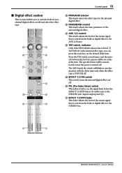
... will be set to the "√" position. The signal is located in the digital effect section is sent to the AUX 1, 2 buses. EMX5000-20/EMX5000-12-Owner's Manual Note: The amount of signal that is sent to the EFFECT 1, 2 bus from the AUX1 and 2 buses to the AUX SEND 1 and...channel fader C (post-fader send). 7 PAN (panpot) control (EMX5000-20: Channels 1-16, EMX5000-12: Channels 1-8) The PAN knobs set the balance between the left at L. 8 BAL (balance) control (EMX5000-20: Channels 17/18-19/20, EMX5000-12: Channels 9/10-11/12) The BAL knobs set the stereo position of signal that is ...
... will be set to the "√" position. The signal is located in the digital effect section is sent to the AUX 1, 2 buses. EMX5000-20/EMX5000-12-Owner's Manual Note: The amount of signal that is sent to the EFFECT 1, 2 bus from the AUX1 and 2 buses to the AUX SEND 1 and...channel fader C (post-fader send). 7 PAN (panpot) control (EMX5000-20: Channels 1-16, EMX5000-12: Channels 1-8) The PAN knobs set the balance between the left at L. 8 BAL (balance) control (EMX5000-20: Channels 17/18-19/20, EMX5000-12: Channels 9/10-11/12) The BAL knobs set the stereo position of signal that is ...
Owner's Manual
Page 14
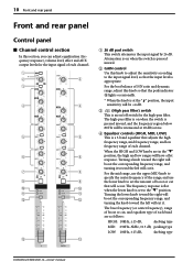
...;nal level of the signal sent to the PFL/AFL buses (pre-fader send). 12 Front and rear panel G PFL (pre-fader listen) switch When this switch is turned on, the signal at the point before the ST control knob F is sent to the PHONES jack (input/output panel D). EMX5000-20/EMX5000-12-Owner's Manual
...;nal level of the signal sent to the PFL/AFL buses (pre-fader send). 12 Front and rear panel G PFL (pre-fader listen) switch When this switch is turned on, the signal at the point before the ST control knob F is sent to the PHONES jack (input/output panel D). EMX5000-20/EMX5000-12-Owner's Manual
Owner's Manual
Page 15
P PARAMETER control This knob adjusts the time parameter of the return signal that is sent from the built-in digital effect to the STEREO bus. U U EMX5000-20/EMX5000-12-Owner's Manual O O P P Q Q R S S T T O PROGRAM selector This knob selects the effect type for the internal digital effect. The specified time will blink in synchronization with the...
P PARAMETER control This knob adjusts the time parameter of the return signal that is sent from the built-in digital effect to the STEREO bus. U U EMX5000-20/EMX5000-12-Owner's Manual O O P P Q Q R S S T T O PROGRAM selector This knob selects the effect type for the internal digital effect. The specified time will blink in synchronization with the...
Owner's Manual
Page 16
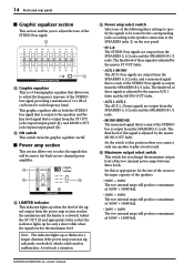
...output to play a loud sound. Set the switch to this as appropriate for a longer duration if the power amp section is activated. EMX5000-20/EMX5000-12-Owner's Manual 14 Front and rear panel s Graphic equalizer section This section enables you to adjust the tone of the two internal power amps between ... following three settings to specify the signals to be sent to adjust the frequency response of the STEREO bus signal, providing a maximum of ±12 dB of the STEREO bus is output from the SPEAKERS B 1/2 jacks. The final level of these signals is adjusted by the master...
...output to play a loud sound. Set the switch to this as appropriate for a longer duration if the power amp section is activated. EMX5000-20/EMX5000-12-Owner's Manual 14 Front and rear panel s Graphic equalizer section This section enables you to adjust the tone of the two internal power amps between ... following three settings to specify the signals to be sent to adjust the frequency response of the STEREO bus signal, providing a maximum of ±12 dB of the STEREO bus is output from the SPEAKERS B 1/2 jacks. The final level of these signals is adjusted by the master...
Owner's Manual
Page 17
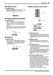
... switch. The "0" indicator lights up when the power of the slit in the control trimmer that are using a sub-woofer. EMX5000-20/EMX5000-12-Owner's Manual First, check the low range balance by auditioning the resultant sound, then set this control does not affect signals that is on... switch This switch applies a low-pass filter to the signal that is on varies depending on . [ s Other indicators and controls ` s YAMAHA SPEAKER PROCESSING \ ON/OFF switch This switch enables you are sent from the STEREO bus to compensate the low range of the signal monitored via...
... switch. The "0" indicator lights up when the power of the slit in the control trimmer that are using a sub-woofer. EMX5000-20/EMX5000-12-Owner's Manual First, check the low range balance by auditioning the resultant sound, then set this control does not affect signals that is on... switch This switch applies a low-pass filter to the signal that is on varies depending on . [ s Other indicators and controls ` s YAMAHA SPEAKER PROCESSING \ ON/OFF switch This switch enables you are sent from the STEREO bus to compensate the low range of the signal monitored via...
Owner's Manual
Page 18
... the external processor to the INSERT I /O (insert) jacks These are TRS phone jacks that enable you to the output jack of the external processor EMX5000-20/EMX5000-12-Owner's Manual Both INPUT A and B are compatible with microphones of output impedance 50-600Ω or line level devices of 600Ω. For this reason, devices...
... the external processor to the INSERT I /O (insert) jacks These are TRS phone jacks that enable you to the output jack of the external processor EMX5000-20/EMX5000-12-Owner's Manual Both INPUT A and B are compatible with microphones of output impedance 50-600Ω or line level devices of 600Ω. For this reason, devices...
Owner's Manual
Page 19
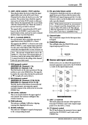
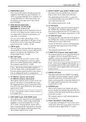
... channels 1-8 (on , the indicator in the upper part of the control panel will light. 4 LINE (stereo) input jacks EMX5000-20: 17/18-19/20, EMX5000-12: 9/10-11/12 These are used to connect to these jacks. Note: If you insert a plug into this jack, the corresponding channel of each... output jack, and is +4 dB. E FOOT SW EFFECT 2 ON/OFF jack A separately sold Yamaha FC5 foot switch can be added to +10 dB. 5 2TR IN jacks These are connecting. EMX5000-20/EMX5000-12-Owner's Manual The nominal output level is used to connect to adjust the final level of electronic instruments...
... channels 1-8 (on , the indicator in the upper part of the control panel will light. 4 LINE (stereo) input jacks EMX5000-20: 17/18-19/20, EMX5000-12: 9/10-11/12 These are used to connect to these jacks. Note: If you insert a plug into this jack, the corresponding channel of each... output jack, and is +4 dB. E FOOT SW EFFECT 2 ON/OFF jack A separately sold Yamaha FC5 foot switch can be added to +10 dB. 5 2TR IN jacks These are connecting. EMX5000-20/EMX5000-12-Owner's Manual The nominal output level is used to connect to adjust the final level of electronic instruments...
Owner's Manual
Page 20
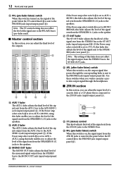
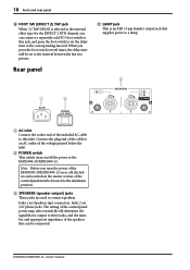
... impedance of the speakers that supplies power to a lamp. 3 1 2 1 AC inlet Connect the socket end of the included AC cable to connect speakers. EMX5000-20/EMX5000-12-Owner's Manual When you press the foot switch several times, the delay time will determine the signal that is an XLR (3-pin female) output jack that... phone jacks. Rear panel G LAMP jack This is output to the interval between the last two presses. Note: Before you turn the power of the EMX5000-20/EMX5000-12 on /off , the faders and controls in the master section of the control panel must be set the delay time to the...
... impedance of the speakers that supplies power to a lamp. 3 1 2 1 AC inlet Connect the socket end of the included AC cable to connect speakers. EMX5000-20/EMX5000-12-Owner's Manual When you press the foot switch several times, the delay time will determine the signal that is an XLR (3-pin female) output jack that... phone jacks. Rear panel G LAMP jack This is output to the interval between the last two presses. Note: Before you turn the power of the EMX5000-20/EMX5000-12 on /off , the faders and controls in the master section of the control panel must be set the delay time to the...
Owner's Manual
Page 21
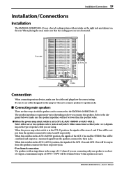
...connected to jacks A and B respectively. When this switch is in the AUX 1-MONO position, the signals of outputs. EMX5000-20/EMX5000-12-Owner's Manual The speaker impedance requirement varies depending on how you are connecting only one or two speakers each set to ST L-R, AUX ...to each to speaker jacks. Installation/Connections 19 Installation/Connections Installation The EMX5000-20/EMX5000-12 uses a forced cooling system with an impedance in which speakers can be connected to the EMX5000-20/EMX5000-12. Make connections to make sure the speaker impedance will be output from...
...connected to jacks A and B respectively. When this switch is in the AUX 1-MONO position, the signals of outputs. EMX5000-20/EMX5000-12-Owner's Manual The speaker impedance requirement varies depending on how you are connecting only one or two speakers each set to ST L-R, AUX ...to each to speaker jacks. Installation/Connections 19 Installation/Connections Installation The EMX5000-20/EMX5000-12 uses a forced cooling system with an impedance in which speakers can be connected to the EMX5000-20/EMX5000-12. Make connections to make sure the speaker impedance will be output from...

