
E1010 Owners Manual Image
Page 1
E1010 OPERATING MANUAL 7 "-..... .. 8 .....s s3, oNG i-atifOCA's S „,:s• 1 3•Z' .... 2"" i';', • / t0i, re ... -,--e ... ... -.F..9 , "•.. • 0 4 . '• i -, 3: .: ,.., 2.....- .-.., i ,, / It 001£0 _, ....8 Z s•s.*.Z-9 2•0 -".'.".• '''\oeLAY 0. 7cr 225 YAMAHA
E1010 OPERATING MANUAL 7 "-..... .. 8 .....s s3, oNG i-atifOCA's S „,:s• 1 3•Z' .... 2"" i';', • / t0i, re ... -,--e ... ... -.F..9 , "•.. • 0 4 . '• i -, 3: .: ,.., 2.....- .-.., i ,, / It 001£0 _, ....8 Z s•s.*.Z-9 2•0 -".'.".• '''\oeLAY 0. 7cr 225 YAMAHA
E1010 Owners Manual Image
Page 2
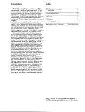
... Delay Line delivers a full 300 milliseconds of this manual thoroughly, and to service. whether the input level is required; It is well suited to reduce noise. In fact, no user serviceable parts inside back cover NOTE: There are rearpanel input and output jacks for rack-mount installations, plus special effects. Guitar players will especially appreciate the E1010's very high input impedance and its original voltage levels throughout the electronics. This instruction manual...
... Delay Line delivers a full 300 milliseconds of this manual thoroughly, and to service. whether the input level is required; It is well suited to reduce noise. In fact, no user serviceable parts inside back cover NOTE: There are rearpanel input and output jacks for rack-mount installations, plus special effects. Guitar players will especially appreciate the E1010's very high input impedance and its original voltage levels throughout the electronics. This instruction manual...
E1010 Owners Manual Image
Page 3
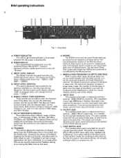
... the Delay time up and down. The display has 9 LED's which indicate peak values from the E1010 output that is useful for low noise and low distortion). INPUT LEVEL CONTROL This control adjusts the input sensitivity for optimum interface (i.e., for vibrato, flanging, phasing, and similar effects. The Bass and Treble controls modify only the delayed signal, not the direct sound. istics of the Mixing control yields all delayed sound. POWER SWITCH This recessed latching pushbutton turns the E1010 AC Power ON...
... the Delay time up and down. The display has 9 LED's which indicate peak values from the E1010 output that is useful for low noise and low distortion). INPUT LEVEL CONTROL This control adjusts the input sensitivity for optimum interface (i.e., for vibrato, flanging, phasing, and similar effects. The Bass and Treble controls modify only the delayed signal, not the direct sound. istics of the Mixing control yields all delayed sound. POWER SWITCH This recessed latching pushbutton turns the E1010 AC Power ON...
E1010 Owners Manual Image
Page 4
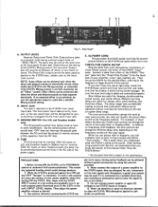
... change the effective delay time, depending on the frequency content of the E1010 "Input" jacks. Do not connect power supplies or apply DC voltages to Lower the volume of the E1010's Mixing control, the rear panel Output jack will provide all delayed, all "Delay" sound). 3 D E *YAMAHA IH Fig. 2 - Depending on other models protects the delay line by using the controls provided. 4. and Canadian models only) This three position switch may be used with the unit, we recommend that the display is set...
... change the effective delay time, depending on the frequency content of the E1010 "Input" jacks. Do not connect power supplies or apply DC voltages to Lower the volume of the E1010's Mixing control, the rear panel Output jack will provide all delayed, all "Delay" sound). 3 D E *YAMAHA IH Fig. 2 - Depending on other models protects the delay line by using the controls provided. 4. and Canadian models only) This three position switch may be used with the unit, we recommend that the display is set...
E1010 Owners Manual Image
Page 5
... jacks. for use with -6dB/octave filter @ 12.47kHz; DEPTH from 0 to 10Hz. OUTPUT DELAY: -87dB* output noise with input volume at maximum (70dB S/N). Net Weight 10 pounds, 4 ounces (4.7 kg) *Ode is ON. Specifications subject to set delay. Modulation Sine-wave variation of delay time relative to change without notice. wired so that phone plug inserted in dB (relative). for U.S. Rear panel Direct output jack. Calibrated in steps of 70Hz and 7kHz, mixed...
... jacks. for use with -6dB/octave filter @ 12.47kHz; DEPTH from 0 to 10Hz. OUTPUT DELAY: -87dB* output noise with input volume at maximum (70dB S/N). Net Weight 10 pounds, 4 ounces (4.7 kg) *Ode is ON. Specifications subject to set delay. Modulation Sine-wave variation of delay time relative to change without notice. wired so that phone plug inserted in dB (relative). for U.S. Rear panel Direct output jack. Calibrated in steps of 70Hz and 7kHz, mixed...
E1010 Owners Manual Image
Page 6
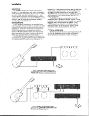
... power transformers). C., C,. CONNECTIONS In rack mounted installations, the rear panel input and output jacks may be placed on Page 8. o T VOL BASS MID HI DIST BRITE • • • • • • 00 Fig. 3 - As with a guitar amp that input. mination (i.e., some passive equalizers rated for special effects with all low-level signal processing equipment, it is advisable to be installed across the signal and shield conductorsof the input cable...
... power transformers). C., C,. CONNECTIONS In rack mounted installations, the rear panel input and output jacks may be placed on Page 8. o T VOL BASS MID HI DIST BRITE • • • • • • 00 Fig. 3 - As with a guitar amp that input. mination (i.e., some passive equalizers rated for special effects with all low-level signal processing equipment, it is advisable to be installed across the signal and shield conductorsof the input cable...
E1010 Owners Manual Image
Page 7
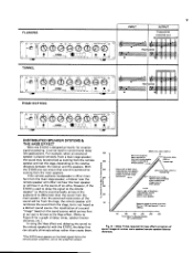
... CH 2 ^ IN Main Speaker (on stage) Remote Speaker (in a distributed sound reinforcement system. In An Echo Send/Return Loop From Master Insert Output To Amps & Speakers • • 1 •• I tololo 0 1919 OOO O1O O PM-1000 1O1O1 1O1O1O1O1 -50dB to -20dB Low-Level Inputs 111111111 1 PM-700 To Amps & Speakers Echo Return Echo Send Fig. 5 - Hookup for delay of a remote speaker in audience) From Mixer Output Splitter or "Y" Adapter Set for delay or special effects with a mixer or console: A.
... CH 2 ^ IN Main Speaker (on stage) Remote Speaker (in a distributed sound reinforcement system. In An Echo Send/Return Loop From Master Insert Output To Amps & Speakers • • 1 •• I tololo 0 1919 OOO O1O O PM-1000 1O1O1 1O1O1O1O1 -50dB to -20dB Low-Level Inputs 111111111 1 PM-700 To Amps & Speakers Echo Return Echo Send Fig. 5 - Hookup for delay of a remote speaker in audience) From Mixer Output Splitter or "Y" Adapter Set for delay or special effects with a mixer or console: A.
E1010 Owners Manual Image
Page 8
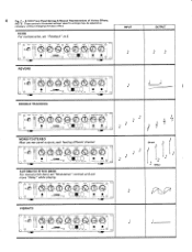
... speakers by mixing the direct and delayed sound. as desired. the varying delay signal beats against it is some overlap in the program. Hollow & Tunnel Effects The E1010can make normal voice or instrumental parts sound like they smear together and have no sharp musical attacks (i.e., legato string lines or melodic vocal backups), then the multiple echoes with one tape machine and the other by setting...
... speakers by mixing the direct and delayed sound. as desired. the varying delay signal beats against it is some overlap in the program. Hollow & Tunnel Effects The E1010can make normal voice or instrumental parts sound like they smear together and have no sharp musical attacks (i.e., legato string lines or melodic vocal backups), then the multiple echoes with one tape machine and the other by setting...
E1010 Owners Manual Image
Page 9
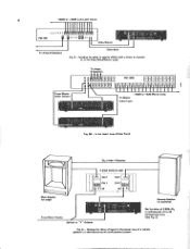
... echo, set "Modulation" controls at0 and move "Delay" while playing. A AA • A , . Ili . . 0 • J 6 0 ' ' -"' 0 'LW I_MIF OUTPUT - .,„ V Direct 1' •1' J\ .1\ Delay \ \\. 8 Fig. 7 - NOTE: Those controls illustrated without specific settings may be adjusted as ,ecessary without changing the basic effect. I IW0 ® • . 'A A• VIBRATO o Pa rAF _ • . *InAftA A" ' i LI on o A ,v. r / J ". 4 :. • INPUT J\ DOUBLE TRACKING - ,....- -. . ....Entt_c) ,. • • 1) MONO-TO-STEREO Must use rear panel...
... echo, set "Modulation" controls at0 and move "Delay" while playing. A AA • A , . Ili . . 0 • J 6 0 ' ' -"' 0 'LW I_MIF OUTPUT - .,„ V Direct 1' •1' J\ .1\ Delay \ \\. 8 Fig. 7 - NOTE: Those controls illustrated without specific settings may be adjusted as ,ecessary without changing the basic effect. I IW0 ® • . 'A A• VIBRATO o Pa rAF _ • . *InAftA A" ' i LI on o A ,v. r / J ". 4 :. • INPUT J\ DOUBLE TRACKING - ,....- -. . ....Entt_c) ,. • • 1) MONO-TO-STEREO Must use rear panel...
E1010 Owners Manual Image
Page 10
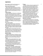
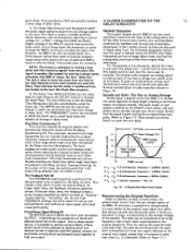
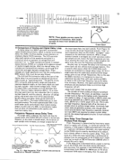
... is used in .885ms). 50 100 150 200 250 300 Time Delay To Remote Speaker (MILLISECONDS) Fig. 8 - delay (338 ft.) Dark line represents delay required for hass effect correction of sound images at various main speaker/remote speaker/listener distances. Hi) Based on speed of sound at sea level, 25° C at 1130 feet/second (1 foot in conventional delay line applications. Delay Times required for main and remote speaker output to...
... is used in .885ms). 50 100 150 200 250 300 Time Delay To Remote Speaker (MILLISECONDS) Fig. 8 - delay (338 ft.) Dark line represents delay required for hass effect correction of sound images at various main speaker/remote speaker/listener distances. Hi) Based on speed of sound at sea level, 25° C at 1130 feet/second (1 foot in conventional delay line applications. Delay Times required for main and remote speaker output to...
E1010 Owners Manual Image
Page 11
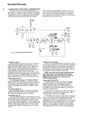
... truly understand how the E1010 to the E1010's tone control and delay circuitry. hence the tone from either the front or rear panel INPUT jack goes through two preamplifiers, one on and making room for delay by the Delay Time Adjustment circuitry, which depicts processes the sound, predict the sound obtained at this section ON, and duplicate effects without affecting the E1010's direct output signal. The INPUT LEVEL display circuits sense the...
... truly understand how the E1010 to the E1010's tone control and delay circuitry. hence the tone from either the front or rear panel INPUT jack goes through two preamplifiers, one on and making room for delay by the Delay Time Adjustment circuitry, which depicts processes the sound, predict the sound obtained at this section ON, and duplicate effects without affecting the E1010's direct output signal. The INPUT LEVEL display circuits sense the...
E1010 Owners Manual Image
Page 12
... sets the speed at some later time (i.e., it along a series of buckets (the BBD's)-hence, the term "delay line." The clock is useful for special effects. voltage controlled oscillator). At shorter delay times, the feedback creates a series of signal cancellations which might have been introduced in that is transferred from one cycle of a simple sine - Direct/Delay Signal Mixing (9) The MIXING control affects the front- Any signal could not be changed...
... sets the speed at some later time (i.e., it along a series of buckets (the BBD's)-hence, the term "delay line." The clock is useful for special effects. voltage controlled oscillator). At shorter delay times, the feedback creates a series of signal cancellations which might have been introduced in that is transferred from one cycle of a simple sine - Direct/Delay Signal Mixing (9) The MIXING control affects the front- Any signal could not be changed...

E1010 Owners Manual Image
Page 13
... without changing their values. This +1 T= 3 process continues with each clock pulse defining a new signal sample and pushing previously defined samples into a series of the # 1 signal sample. +1 T =1 STORED VOLTAGE 0 0 0 0 0 0 0 0 00 IN l- F l- l- -IF -II- -IF -IF-IF -.4V 1 2 3 4 5 6 7 8 9 10 STORAGE REGISTER NUMBER 0 -IF OD T 4096 T = 2 The next clock pulse marks the end of the #1 sample and the beginning of time...
... without changing their values. This +1 T= 3 process continues with each clock pulse defining a new signal sample and pushing previously defined samples into a series of the # 1 signal sample. +1 T =1 STORED VOLTAGE 0 0 0 0 0 0 0 0 00 IN l- F l- l- -IF -II- -IF -IF-IF -.4V 1 2 3 4 5 6 7 8 9 10 STORAGE REGISTER NUMBER 0 -IF OD T 4096 T = 2 The next clock pulse marks the end of the #1 sample and the beginning of time...

E1010 Owners Manual Image
Page 14
...begin to appear at the BBD's last storage register, ready for output as voltages. +1 T = 11 T = 4096 to T = 5006 The samples continue moving out of the BBD until the entire signal has been output as a rough waveform, a string of discrete voltage steps. ...«11 T =4096 ° +.7V STORED VOLTAGE +10 +.70 +.2 -.2 -.7 -1 -.9 -.4 0 0 / it 0 IN 1 2 3 4 5 6 7 8 9 10 STORAGE REGISTER NUMBER OUT 4096 STORED VOLTAGE +.2V +7V +1V +7V +2 -1 0 IN...
...begin to appear at the BBD's last storage register, ready for output as voltages. +1 T = 11 T = 4096 to T = 5006 The samples continue moving out of the BBD until the entire signal has been output as a rough waveform, a string of discrete voltage steps. ...«11 T =4096 ° +.7V STORED VOLTAGE +10 +.70 +.2 -.2 -.7 -1 -.9 -.4 0 0 / it 0 IN 1 2 3 4 5 6 7 8 9 10 STORAGE REGISTER NUMBER OUT 4096 STORED VOLTAGE +.2V +7V +1V +7V +2 -1 0 IN...
E1010 Owners Manual Image
Page 15
...-IF -IF -IF-IF-IF-IF-IF-IF -IF OUT 1 2 3 4 5 6 7 B 9 10 4096 STORAGE REGISTER NUMBER 1 *NOTE: At a clock rate of 50kHz, T5O00 equals 1/10 second of delay (100 milliseconds). STORES VOLTAGE 0 0 0 0 0 0 0 0 00 7V IN AHHHHHHHHHEfit OUT 1 2 3 4 5 6 7 8 9 10 4096 STORAGE REGISTER NUMBER +1 STORED VOLTAGE 0 0 0 0 0 0 0 0 00 f IV IN -11--I - STORED VOLTAGE 0 0 0 0 0 0 0 0 0 0 / / -.7V IN -1-11-1I- 1--I I FIF...
...-IF -IF -IF-IF-IF-IF-IF-IF -IF OUT 1 2 3 4 5 6 7 B 9 10 4096 STORAGE REGISTER NUMBER 1 *NOTE: At a clock rate of 50kHz, T5O00 equals 1/10 second of delay (100 milliseconds). STORES VOLTAGE 0 0 0 0 0 0 0 0 00 7V IN AHHHHHHHHHEfit OUT 1 2 3 4 5 6 7 8 9 10 4096 STORAGE REGISTER NUMBER +1 STORED VOLTAGE 0 0 0 0 0 0 0 0 00 f IV IN -11--I - STORED VOLTAGE 0 0 0 0 0 0 0 0 0 0 / / -.7V IN -1-11-1I- 1--I I FIF...
E1010 Owners Manual Image
Page 16
... BBD's function, it was input. The number of clock pulses per cycle of Bucket Brigade Device when low f equency is applied to input. and vice-versa. LOW PASS FILTER NOTE: These samples are lost. Output Signal A Comparison of the waveform and gives it does lengthen the delay time, also cuts the frequency bandwidth. the input signal falls into each sample of Analog and Digital Delay Lines A digital delay l ine...
... BBD's function, it was input. The number of clock pulses per cycle of Bucket Brigade Device when low f equency is applied to input. and vice-versa. LOW PASS FILTER NOTE: These samples are lost. Output Signal A Comparison of the waveform and gives it does lengthen the delay time, also cuts the frequency bandwidth. the input signal falls into each sample of Analog and Digital Delay Lines A digital delay l ine...
E1010 Owners Manual Image
Page 17
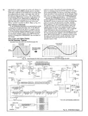
... sustained pitch-changed output re-circulates through the delay unit, sustaining whatever pitch was changing - How changing the clock rate as the delay 1kHz wave is emerging from the E1010 output as a signal emerges from E1010. 500Hz Sine Wave (A Pitch of the change and FREQUENCY sets the speed of Input Signal) 4mS k 8mS Clock Rate = 20kHz Clock Rate = 10kHz Fig. 13 - FUSE POWER SUPPLY LED ON OFF ON GROUND 10 O75 11501225 O300 ? E1010 Block Diagram...
... sustained pitch-changed output re-circulates through the delay unit, sustaining whatever pitch was changing - How changing the clock rate as the delay 1kHz wave is emerging from the E1010 output as a signal emerges from E1010. 500Hz Sine Wave (A Pitch of the change and FREQUENCY sets the speed of Input Signal) 4mS k 8mS Clock Rate = 20kHz Clock Rate = 10kHz Fig. 13 - FUSE POWER SUPPLY LED ON OFF ON GROUND 10 O75 11501225 O300 ? E1010 Block Diagram...


