
E1005 Owners Manual Image
Page 2
... echo machines. A second output carries delayed signal only for low distortion and noise. The term "analog" means that the audio signal retains its own input level control. A very high input impedance ensures that enable it as binary numbers. The E1005 Analog Delay Line provides variable time delay up to conveniently turn the effects On and Off. A bar type input level display makes it easy to adjust the levels for stereo synthesis, pure delay, and other special effects. All controls...
... echo machines. A second output carries delayed signal only for low distortion and noise. The term "analog" means that the audio signal retains its own input level control. A very high input impedance ensures that enable it as binary numbers. The E1005 Analog Delay Line provides variable time delay up to conveniently turn the effects On and Off. A bar type input level display makes it easy to adjust the levels for stereo synthesis, pure delay, and other special effects. All controls...
E1005 Owners Manual Image
Page 3
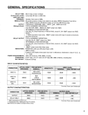
... Phone Jack (Unbalanced) CONNECTION ACTUAL SOURCE IMPEDANCE OUTPUT 2502 DELAY ONLY 2502 * 0dB is ON. Specifications are subject to 0.775 Vr.m.s. ** Compensated with Input A volume at maximum, Input B at minimum. to 5k2 MICROPHONE OUTPUT CHARACTERISTICS SENSITIVITY -50dB -30dB -50dB INPUT LEVEL NOMINAL MAX. INPUT B MIC. 500k12 25k11 FOR USE WITH NOMINAL 150 to 5k,S2 MICROPHONE 5kS2 LINE & INSTRUMENT 150 to 400 msec. SPEED (frequency) from 0 to set delay. NOISE...
... Phone Jack (Unbalanced) CONNECTION ACTUAL SOURCE IMPEDANCE OUTPUT 2502 DELAY ONLY 2502 * 0dB is ON. Specifications are subject to 0.775 Vr.m.s. ** Compensated with Input A volume at maximum, Input B at minimum. to 5k2 MICROPHONE OUTPUT CHARACTERISTICS SENSITIVITY -50dB -30dB -50dB INPUT LEVEL NOMINAL MAX. INPUT B MIC. 500k12 25k11 FOR USE WITH NOMINAL 150 to 5k,S2 MICROPHONE 5kS2 LINE & INSTRUMENT 150 to 400 msec. SPEED (frequency) from 0 to set delay. NOISE...
E1005 Owners Manual Image
Page 4
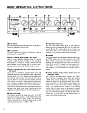
... display monitors the signal level after the E1005 Input level controls, and has 5 LED's which indicate peak values from the minimum to high impedance circuits such as Input A. The Mixing control adjusts the Output jack for connection to the maximum within the selected range. Full counterclockwise rotation of direct and delayed sound. it OFF. ©Power Indicator This LED (Light Emitting Diode) is illuminated whenever the AC power is switched ON. 0 Input A (Includes Input Jack...
... display monitors the signal level after the E1005 Input level controls, and has 5 LED's which indicate peak values from the minimum to high impedance circuits such as Input A. The Mixing control adjusts the Output jack for connection to the maximum within the selected range. Full counterclockwise rotation of direct and delayed sound. it OFF. ©Power Indicator This LED (Light Emitting Diode) is illuminated whenever the AC power is switched ON. 0 Input A (Includes Input Jack...

E1005 Owners Manual Image
Page 5
... connecting the E1005 output to mic or line levels.) 5. DO NOT connect power supplies, batteries, or apply DC voltages to minimum (full counterclockwise). The Depth knob sets the amount of the power supply. REAR PANEL Fuse This 0.5 amp fuse (for initiating an echo effect at about 0dB. AC Power Cord This 2-wire AC power cord may be used if it is handy for nominal 120 VAC mains) protects the delay line by using the controls provided. 4. BEFORE TURNING ON the E1005, set its input...
... connecting the E1005 output to mic or line levels.) 5. DO NOT connect power supplies, batteries, or apply DC voltages to minimum (full counterclockwise). The Depth knob sets the amount of the power supply. REAR PANEL Fuse This 0.5 amp fuse (for initiating an echo effect at about 0dB. AC Power Cord This 2-wire AC power cord may be used if it is handy for nominal 120 VAC mains) protects the delay line by using the controls provided. 4. BEFORE TURNING ON the E1005, set its input...
E1005 Owners Manual Image
Page 6
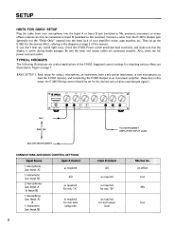
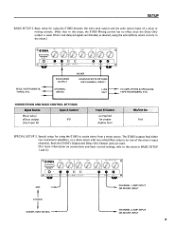
... .1 CONNECTIONS AND BASIC CONTROL SETTINGS Signal Source Input A Control 1 microphone (use Input A) 1 instrument (use Input B) 2 microphones (use Input A & Input B) 1 microphone (use Input A) & 1 instrument (use Input B) as required #0 as required for mic "A" as required for obtaining various effects are illustrated in this manual. no effect Inst Mic Inst BASIC SETUP 1. SETUP HINTS FOR QUICK SETUP Plug the cable from the E1005's Output jack (generally not the "Delay Only" output) into the input jack of your microphone into the Input A or Input B jack (switched to the diagrams...
... .1 CONNECTIONS AND BASIC CONTROL SETTINGS Signal Source Input A Control 1 microphone (use Input A) 1 instrument (use Input B) 2 microphones (use Input A & Input B) 1 microphone (use Input A) & 1 instrument (use Input B) as required #0 as required for mic "A" as required for obtaining various effects are illustrated in this manual. no effect Inst Mic Inst BASIC SETUP 1. SETUP HINTS FOR QUICK SETUP Plug the cable from the E1005's Output jack (generally not the "Delay Only" output) into the input jack of your microphone into the Input A or Input B jack (switched to the diagrams...
E1005 Owners Manual Image
Page 7
ECHO SEND OUTPUT CHANNEL INPUTS MIXER ECHO/EFFECTS RETURN (OR CHANNEL INPUTi LINE OUT TO AMPLIFIERS & SPEAKERS, TAPE RECORDERS, ETC. The El 005 outputs feed either two instrument amplifiers, or a stereo mixer with two echo/effects returns (or two of a mixer or mixing console. (Note that in this setup, the E1005 Mixing control has no effect since the Delay Only output is used . (For more information on connections and basic control settings, refer to create stereo from a mono source. Both the E1005's Output and Delay Only Output jacks are blended, as...
ECHO SEND OUTPUT CHANNEL INPUTS MIXER ECHO/EFFECTS RETURN (OR CHANNEL INPUTi LINE OUT TO AMPLIFIERS & SPEAKERS, TAPE RECORDERS, ETC. The El 005 outputs feed either two instrument amplifiers, or a stereo mixer with two echo/effects returns (or two of a mixer or mixing console. (Note that in this setup, the E1005 Mixing control has no effect since the Delay Only output is used . (For more information on connections and basic control settings, refer to create stereo from a mono source. Both the E1005's Output and Delay Only Output jacks are blended, as...
E1005 Owners Manual Image
Page 8
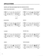
STEREO FROM A MONO SOURCE AUTOMATIC DOUBLE TRACKING o,0 YAMAHA I O• 0 .. . O• 0 o 0 LI Ill -... - .. - 0 0 0 - 0 MACHINE VOICE C,® YAMAHA O• a 07 11 O 0 - - 0 CHORUS O•® YAMAHA ,._.,.., O• .,,,., 007 , ,,, ,, . , ,,; 11 O0 O -1 ROTARY SPEAKER (3 0 yAM6HA .,, ' • ., , ,,; a 0O -- 0 FLANGING ° IDYIMPA. O • 0. 0 7 U O 0 O 0 7 APPLICATIONS CONTROL SETTINGS AND CONNECTIONS FOR VARIOUS EFFECTS. o a - .. . (3 0 YAMAHA, O• O 0 7 a O0 O ECHO/REVERB R OUTPUT O.O YAMAHA II 1 O&#...
STEREO FROM A MONO SOURCE AUTOMATIC DOUBLE TRACKING o,0 YAMAHA I O• 0 .. . O• 0 o 0 LI Ill -... - .. - 0 0 0 - 0 MACHINE VOICE C,® YAMAHA O• a 07 11 O 0 - - 0 CHORUS O•® YAMAHA ,._.,.., O• .,,,., 007 , ,,, ,, . , ,,; 11 O0 O -1 ROTARY SPEAKER (3 0 yAM6HA .,, ' • ., , ,,; a 0O -- 0 FLANGING ° IDYIMPA. O • 0. 0 7 U O 0 O 0 7 APPLICATIONS CONTROL SETTINGS AND CONNECTIONS FOR VARIOUS EFFECTS. o a - .. . (3 0 YAMAHA, O• O 0 7 a O0 O ECHO/REVERB R OUTPUT O.O YAMAHA II 1 O&#...
E1005 Owners Manual Image
Page 9
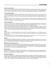
..., delayed sound images with the direct signal to create changing phase cancellations that sweep across the various overtones. Double tracking is obtained. "Reverb" also consists of multiple delayed sound images, but there is no sharp musical attacks (i.e., legato string lines or melodic vocal backups), then the multiple echoes with the El 005 analog delay line. APPLICATIONS Stereo From a Mono Source Delay the sound to one of two speakers using the E1005 in...
..., delayed sound images with the direct signal to create changing phase cancellations that sweep across the various overtones. Double tracking is obtained. "Reverb" also consists of multiple delayed sound images, but there is no sharp musical attacks (i.e., legato string lines or melodic vocal backups), then the multiple echoes with the El 005 analog delay line. APPLICATIONS Stereo From a Mono Source Delay the sound to one of two speakers using the E1005 in...
E1005 Owners Manual Image
Page 10
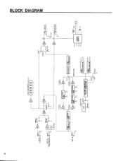
... °5--.O--IEXPANDOR_1 DEEMPHASISF - 48,d8/oct LONG - "SPEED TO VOLTAGE CONTROLED CLOCK GENERATOR SHORT 0 r BBD CLOCK DRIVER CPI CP2 BBD CLOCKDRIVER CPI cp2 r., +15 E -IS +8 POWER FUSE POWER SUPPLY LED LONG DELAY w 0 C) C7 5 LEDs PEAK METER( InputLevel) BA INPUT A -50d8/25KO. ai* COMPRES- SU FEEDBACK MIXING \7777 SU DELAY BA 0 OUTPUT -20 dB/250C1 FET SWITCHES ° : DA_i DE2LoAd40/ 02N5LoYa EFT. L. LPF 4096 stage __I4096...
... °5--.O--IEXPANDOR_1 DEEMPHASISF - 48,d8/oct LONG - "SPEED TO VOLTAGE CONTROLED CLOCK GENERATOR SHORT 0 r BBD CLOCK DRIVER CPI CP2 BBD CLOCKDRIVER CPI cp2 r., +15 E -IS +8 POWER FUSE POWER SUPPLY LED LONG DELAY w 0 C) C7 5 LEDs PEAK METER( InputLevel) BA INPUT A -50d8/25KO. ai* COMPRES- SU FEEDBACK MIXING \7777 SU DELAY BA 0 OUTPUT -20 dB/250C1 FET SWITCHES ° : DA_i DE2LoAd40/ 02N5LoYa EFT. L. LPF 4096 stage __I4096...

E1005 Owners Manual Image
Page 11
... are no user-serviceable parts in locating a Yamaha dealer, contact Yamaha Combo Product Service at the address given below . Refer servicing to familiarize yourself with its authorized service center will replace the defective product with the E1005 should you plan to Yamaha the Warranty Registration Card within ten (10) days of purchase. In the event Yamaha determines that every new Yamaha product owner understand this...
... are no user-serviceable parts in locating a Yamaha dealer, contact Yamaha Combo Product Service at the address given below . Refer servicing to familiarize yourself with its authorized service center will replace the defective product with the E1005 should you plan to Yamaha the Warranty Registration Card within ten (10) days of purchase. In the event Yamaha determines that every new Yamaha product owner understand this...


