

Owner's Manual
Page 2
... listening environments-anything from Dolby-Surround encoded video sources using the built-in a safe place for later reference. In addition, you a whole new world of a Yamaha Digital Sound Field Processing (DSP) System-an extremely sophisticated audio component. You are required to a cozy jazz club. Seven built-in channels of amplification on this operation manual carefully and store it in Dolby Pro Logic Surround Decoder and Dolby Digital (AC-3) Decoder.
... listening environments-anything from Dolby-Surround encoded video sources using the built-in a safe place for later reference. In addition, you a whole new world of a Yamaha Digital Sound Field Processing (DSP) System-an extremely sophisticated audio component. You are required to a cozy jazz club. Seven built-in channels of amplification on this operation manual carefully and store it in Dolby Pro Logic Surround Decoder and Dolby Digital (AC-3) Decoder.
Owner's Manual
Page 3
... is on the rear of time (ie., vacation, etc.), disconnect the AC power plug from locations where it is marked with a soft, dry cloth. 9. Model: Serial No.: The serial number is located on , otherwise this Owner's Manual in the mains lead are subject to this unit is coloured BLUE must be destroyed, as tuners, receivers or TVs. The wire which is...
... is on the rear of time (ie., vacation, etc.), disconnect the AC power plug from locations where it is marked with a soft, dry cloth. 9. Model: Serial No.: The serial number is located on , otherwise this Owner's Manual in the mains lead are subject to this unit is coloured BLUE must be destroyed, as tuners, receivers or TVs. The wire which is...
Owner's Manual
Page 4
...REAR PANEL PARTS AND THEIR FUNCTIONS 17 REAR PANEL SWITCH AND CONTROL SETTINGS 20 GENERAL INSTRUCTIONS FOR CONNECTIONS 20 CONNECTING AUDIO/VIDEO SOURCE EQUIPMENT TO THIS UNIT 21 CONNECTING SPEAKER SYSTEMS 25 SELECTING THE OUTPUT MODES SUITABLE FOR YOUR SPEAKER SYSTEM 30 SPEAKER BALANCE ADJUSTMENT 33 ADJUSTMENTS IN THE "SET MENU" MODE 35 GENERAL OPERATION 38 PLAYING A SOURCE 38 RECORDING A SOURCE TO AUDIO/VIDEO TAPE (OR DUBBING FROM A TAPE TO ANOTHER 40 SELECTING SOUND FIELD PROGRAMS 42 CANCELING THE EFFECT SOUND 43 DESCRIPTIONS OF THE SOUND FIELD PROGRAMS 44 ADJUSTING DELAY TIME...
...REAR PANEL PARTS AND THEIR FUNCTIONS 17 REAR PANEL SWITCH AND CONTROL SETTINGS 20 GENERAL INSTRUCTIONS FOR CONNECTIONS 20 CONNECTING AUDIO/VIDEO SOURCE EQUIPMENT TO THIS UNIT 21 CONNECTING SPEAKER SYSTEMS 25 SELECTING THE OUTPUT MODES SUITABLE FOR YOUR SPEAKER SYSTEM 30 SPEAKER BALANCE ADJUSTMENT 33 ADJUSTMENTS IN THE "SET MENU" MODE 35 GENERAL OPERATION 38 PLAYING A SOURCE 38 RECORDING A SOURCE TO AUDIO/VIDEO TAPE (OR DUBBING FROM A TAPE TO ANOTHER 40 SELECTING SOUND FIELD PROGRAMS 42 CANCELING THE EFFECT SOUND 43 DESCRIPTIONS OF THE SOUND FIELD PROGRAMS 44 ADJUSTING DELAY TIME...
Owner's Manual
Page 12
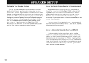
... for reproducing the LFE (low frequency effect) sound with high fidelity when playing back a source with the full system. Use of a subwoofer and amplifier. A four-speaker system using two extra pairs of a Yamaha Active Servo Processing Subwoofer System, which has its own built-in power amplifier. 10 You can always upgrade to further expand your Audio/Video home theater system, it is still performed, but also for reinforcing bass frequencies from the center channel.
... for reproducing the LFE (low frequency effect) sound with high fidelity when playing back a source with the full system. Use of a subwoofer and amplifier. A four-speaker system using two extra pairs of a Yamaha Active Servo Processing Subwoofer System, which has its own built-in power amplifier. 10 You can always upgrade to further expand your Audio/Video home theater system, it is still performed, but also for reinforcing bass frequencies from the center channel.
Owner's Manual
Page 15
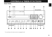
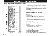
English CONTROLS & THEIR FUNCTIONS FRONT PANEL 1 23 4 5 6 NATURAL SOUND AV AMPLIFIER DSP-A1092 CINEMA DSP 7ch (Europe Model) POWER PHONES A B SPEAKERS ON OFF BASS TONE EXTENSION BYPASS l 0l 2 2 3 3 4 5 4 5 BASS l 0l 2 2 3 3 4 5 4 5 TREBLE l 0l 2 2 3 3 4 L5 4 5R BALANCE VCR 2 VCR 1 VIDEO AUX TAPE (MD) TUNER PHONO DVD/LD TV/DBS CD VOLUME l6 20 l2 28 8 40 4 60 2 0 -dB SOURCE DVD/LD TAPE (MD) TV/DBS TUNER VCR 1 CD VCR 2 PHONO VIDEO AUX REC OUT PROGRAM SET MENU DELAY/C/R /F/SWFR EFFECT S VIDEO VIDEO L AUDIO R VIDEO AUX 78...
English CONTROLS & THEIR FUNCTIONS FRONT PANEL 1 23 4 5 6 NATURAL SOUND AV AMPLIFIER DSP-A1092 CINEMA DSP 7ch (Europe Model) POWER PHONES A B SPEAKERS ON OFF BASS TONE EXTENSION BYPASS l 0l 2 2 3 3 4 5 4 5 BASS l 0l 2 2 3 3 4 5 4 5 TREBLE l 0l 2 2 3 3 4 L5 4 5R BALANCE VCR 2 VCR 1 VIDEO AUX TAPE (MD) TUNER PHONO DVD/LD TV/DBS CD VOLUME l6 20 l2 28 8 40 4 60 2 0 -dB SOURCE DVD/LD TAPE (MD) TV/DBS TUNER VCR 1 CD VCR 2 PHONO VIDEO AUX REC OUT PROGRAM SET MENU DELAY/C/R /F/SWFR EFFECT S VIDEO VIDEO L AUDIO R VIDEO AUX 78...
Owner's Manual
Page 16
... tone (BASS and TREBLE) control circuitry so that no DSP program name is unaffected by speaker positions or listening room conditions. A BASS and TREBLE Controls Adjust low and high frequency response respectively for sound imbalance caused by the tone control circuitry. Press this switch to release it is illuminated on the display panel) by pressing the MUTE key on the remote control unit, the indicator on the master VOLUME control flashes on and off. 7 PHONES Jack...
... tone (BASS and TREBLE) control circuitry so that no DSP program name is unaffected by speaker positions or listening room conditions. A BASS and TREBLE Controls Adjust low and high frequency response respectively for sound imbalance caused by the tone control circuitry. Press this switch to release it is illuminated on the display panel) by pressing the MUTE key on the remote control unit, the indicator on the master VOLUME control flashes on and off. 7 PHONES Jack...

Owner's Manual
Page 17
... number of selections is reduced. I Auxiliary Input Jacks (VIDEO AUX) Connect an auxiliary video or audio unit such as a camcorder to these jacks can be turned OFF to disable output from the main speakers. The unit connected to the main channels and output from the center and effect speakers so that the sound becomes normal 2-channels. * Even if this switch can be selected. J Control Door See page 4 for functions selected by pressing the SET MENU switch. G -/+ Button Adjusts the level of changing delay time, center speaker output level, rear speaker output level...
... number of selections is reduced. I Auxiliary Input Jacks (VIDEO AUX) Connect an auxiliary video or audio unit such as a camcorder to these jacks can be turned OFF to disable output from the main speakers. The unit connected to the main channels and output from the center and effect speakers so that the sound becomes normal 2-channels. * Even if this switch can be selected. J Control Door See page 4 for functions selected by pressing the SET MENU switch. G -/+ Button Adjusts the level of changing delay time, center speaker output level, rear speaker output level...
Owner's Manual
Page 19
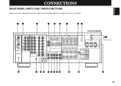
...SPEAKER SET SPEAKER MODE REAR 8ΩMIN./ SPEAKER MAIN A OR B: 8ΩMIN./ SPEAKER A B: 6ΩMIN./ SPEAKER FRONT EFFECT: 8ΩMIN./ SPEAKER I00W MAX. TOTAL 0 A B C DEFGH I J K 17 English CONNECTIONS REAR PANEL PARTS AND THEIR FUNCTIONS Before you start making connections make sure all related electronic components are turned OFF. 12 3 4 56 7 89 PCM/ DIGITAL IN COAXIAL DVD/LD OPTICAL COAXIAL AUDIO SIGNAL PHONO 1 CD 2 TUNER TV/DBS OPTICAL (AC-3 DIGITAL IN) 3 TAPE PB TAPE(MD) 4 REC OUT GND AUDIO SIGNAL VIDEO SIGNAL OUTPUT VIDEO S VIDEO C CENTER C DVD/LD DVD...
...SPEAKER SET SPEAKER MODE REAR 8ΩMIN./ SPEAKER MAIN A OR B: 8ΩMIN./ SPEAKER A B: 6ΩMIN./ SPEAKER FRONT EFFECT: 8ΩMIN./ SPEAKER I00W MAX. TOTAL 0 A B C DEFGH I J K 17 English CONNECTIONS REAR PANEL PARTS AND THEIR FUNCTIONS Before you start making connections make sure all related electronic components are turned OFF. 12 3 4 56 7 89 PCM/ DIGITAL IN COAXIAL DVD/LD OPTICAL COAXIAL AUDIO SIGNAL PHONO 1 CD 2 TUNER TV/DBS OPTICAL (AC-3 DIGITAL IN) 3 TAPE PB TAPE(MD) 4 REC OUT GND AUDIO SIGNAL VIDEO SIGNAL OUTPUT VIDEO S VIDEO C CENTER C DVD/LD DVD...
Owner's Manual
Page 20
... rear-channel amplifier, connect the rear speakers here. 9 VOLTAGE SELECTOR (General Model only) Be sure to set to the DVD/LD COAXIAL or OPTICAL jack. In some cases, however, better results may be used for AC-3 discrete audio signals, connect the AC-3 RF output jack to the standard that is connected to the DVD/LD AUDIO/VIDEO SIGNAL connection jacks to "0 dB". 1 PCM/ DIGITAL IN (COAXIAL and OPTICAL) jacks Can be connected to input jack(s) of one or two external power amplifier(s) to drive the center speaker(s). 5 CENTER SPEAKERS...
... rear-channel amplifier, connect the rear speakers here. 9 VOLTAGE SELECTOR (General Model only) Be sure to set to the DVD/LD COAXIAL or OPTICAL jack. In some cases, however, better results may be used for AC-3 discrete audio signals, connect the AC-3 RF output jack to the standard that is connected to the DVD/LD AUDIO/VIDEO SIGNAL connection jacks to "0 dB". 1 PCM/ DIGITAL IN (COAXIAL and OPTICAL) jacks Can be connected to input jack(s) of one or two external power amplifier(s) to drive the center speaker(s). 5 CENTER SPEAKERS...

Owner's Manual
Page 21
.... Connected with 2 sets of LFE (low frequency effect) generated when the Dolby Digital (AC-3) is used . Not connected when using one subwoofer, connect its amplifier input to MAIN IN jacks when the built-in main-channel amplifier, connect the main speakers here. H REAR OUTPUT Jacks Rear-channel line output. K SWITCHED AC OUTLET(S) You may plug other audio/video units into these jacks. "Switched" means that these jacks. E MAIN IN Jacks Line input to the PRE OUT jacks. F SUBWOOFER Jacks When using an external power amplifier. The jumper bars must be connected to input jacks...
.... Connected with 2 sets of LFE (low frequency effect) generated when the Dolby Digital (AC-3) is used . Not connected when using one subwoofer, connect its amplifier input to MAIN IN jacks when the built-in main-channel amplifier, connect the main speakers here. H REAR OUTPUT Jacks Rear-channel line output. K SWITCHED AC OUTLET(S) You may plug other audio/video units into these jacks. "Switched" means that these jacks. E MAIN IN Jacks Line input to the PRE OUT jacks. F SUBWOOFER Jacks When using an external power amplifier. The jumper bars must be connected to input jacks...

Owner's Manual
Page 25
... player AC-3 RF OUT ANALOG OUT COAXIAL DIGITAL OUT AC-3 RF IN COAXIAL DIGITAL OUT OPTICAL DIGITAL OUT RF demodulator (YAMAHA APD-1 etc.) PCM/ DIGITAL IN COAXIAL DVD/LD OPTICAL COAXIAL TV/DBS OPTICAL AUDIO SIGNAL PHONO 1 CD 2 TUNER 3 TAPE PB TAPE(MD) 4 REC OUT GND AUDIO SIGNAL DVD/LD TV/DBS IN VCR 1 OUT IN VCR 2 OUT MONITOR OUT 23 English This connection is necessary for details about switching the input mode. However, if your LD player has AC-3 RF signal output jack...
... player AC-3 RF OUT ANALOG OUT COAXIAL DIGITAL OUT AC-3 RF IN COAXIAL DIGITAL OUT OPTICAL DIGITAL OUT RF demodulator (YAMAHA APD-1 etc.) PCM/ DIGITAL IN COAXIAL DVD/LD OPTICAL COAXIAL TV/DBS OPTICAL AUDIO SIGNAL PHONO 1 CD 2 TUNER 3 TAPE PB TAPE(MD) 4 REC OUT GND AUDIO SIGNAL DVD/LD TV/DBS IN VCR 1 OUT IN VCR 2 OUT MONITOR OUT 23 English This connection is necessary for details about switching the input mode. However, if your LD player has AC-3 RF signal output jack...

Owner's Manual
Page 28
... speaker output terminals of a stereo power amplifier with a stereo pin cable-making sure to connect the left and right channels correctly. Main speaker A Power amplifier INPUT PRE OUT This unit Main speaker B Main speaker A Main speaker B 26 It is also possible to use to the ON position. Make sure that the jumper bars between the PRE OUT and MAIN IN jacks on the rear panel are shown by the lighting of "SPEAKERS A" and/or "SPEAKERS...
... speaker output terminals of a stereo power amplifier with a stereo pin cable-making sure to connect the left and right channels correctly. Main speaker A Power amplifier INPUT PRE OUT This unit Main speaker B Main speaker A Main speaker B 26 It is also possible to use to the ON position. Make sure that the jumper bars between the PRE OUT and MAIN IN jacks on the rear panel are shown by the lighting of "SPEAKERS A" and/or "SPEAKERS...

Owner's Manual
Page 35
... key to use the remote control unit with the remote control unit. Remote control TIME/LEVEL SET MENU 2. Center CENTER Right rear R SUR. Adjust the level of the speaker selected in step 3 by an image of audio listening room.) This is pressed, the speaker selection changes in turn as follows. key so that of each speaker level. Repeat step 3 and 4 to the TIME/LEVEL position. The adjustment of the main speakers. * While adjusting, the test-tone is set to enter test mode. Adjust the master VOLUME to a normal...
... key to use the remote control unit with the remote control unit. Remote control TIME/LEVEL SET MENU 2. Center CENTER Right rear R SUR. Adjust the level of the speaker selected in step 3 by an image of audio listening room.) This is pressed, the speaker selection changes in turn as follows. key so that of each speaker level. Repeat step 3 and 4 to the TIME/LEVEL position. The adjustment of the main speakers. * While adjusting, the test-tone is set to enter test mode. Adjust the master VOLUME to a normal...

Owner's Manual
Page 37
... panel Remote control SET or MENU 3. NOTE: Be sure to use the remote control unit, set the TIME/LEVEL·SET MENU switch to display information on the monitor, turn the power of your system and expand your enjoyment for audio listening and video watching. 1. Select the function (title) on . 1. If you want to the SET MENU position on this unit's display panel or the monitor screen. Select any desired position or edit parameters on any other function. 35 DYNAMIC RANGE...
... panel Remote control SET or MENU 3. NOTE: Be sure to use the remote control unit, set the TIME/LEVEL·SET MENU switch to display information on the monitor, turn the power of your system and expand your enjoyment for audio listening and video watching. 1. Select the function (title) on . 1. If you want to the SET MENU position on this unit's display panel or the monitor screen. Select any desired position or edit parameters on any other function. 35 DYNAMIC RANGE...

Owner's Manual
Page 41
... source only, the input mode selected on the function "8. Digital input signal from the OPTICAL jack 2. Analog input signal ANALOG: In this unit. Notes on using the input selector buttons • Note that pressing on each input selector button selects the source which was used ) which is connected to the corresponding input terminals on the rear panel. * To select the source connected to the VIDEO AUX terminals on the front panel, press VIDEO AUX. • Once you play a video source, its video image will automatically recalled. Switching the input mode (for DVD...
... source only, the input mode selected on the function "8. Digital input signal from the OPTICAL jack 2. Analog input signal ANALOG: In this unit. Notes on using the input selector buttons • Note that pressing on each input selector button selects the source which was used ) which is connected to the corresponding input terminals on the rear panel. * To select the source connected to the VIDEO AUX terminals on the front panel, press VIDEO AUX. • Once you play a video source, its video image will automatically recalled. Switching the input mode (for DVD...

Owner's Manual
Page 42
Front panel Remote control VCR 1 DVD/LD or TAPE (MD) TV/DBS DVD/LD 3. Front panel SOURCE DVD/LD TAPE (MD) TV/DBS TUNER VCR 1 CD VCR 2 PHONO VIDEO AUX REC OUT 2. Play the source and increase the setting of the master VOLUME control to confirm it with the lid open. 1. Set the tape deck, MD recorder or VCR used for a moment because the digital input signal is selected again. 40 RECORDING A SOURCE TO AUDIO/VIDEO TAPE (OR DUBBING FROM A TAPE TO ANOTHER) NOTE...
Front panel Remote control VCR 1 DVD/LD or TAPE (MD) TV/DBS DVD/LD 3. Front panel SOURCE DVD/LD TAPE (MD) TV/DBS TUNER VCR 1 CD VCR 2 PHONO VIDEO AUX REC OUT 2. Play the source and increase the setting of the master VOLUME control to confirm it with the lid open. 1. Set the tape deck, MD recorder or VCR used for a moment because the digital input signal is selected again. 40 RECORDING A SOURCE TO AUDIO/VIDEO TAPE (OR DUBBING FROM A TAPE TO ANOTHER) NOTE...

Owner's Manual
Page 49
... order. 3. Remote control TIME/LEVEL SET MENU 2. DELAY TIME (Delay time) CENTER LEVEL R SUR. Adjust its level. Front panel Remote control Whenever pressed, the selection changes as you prefer. If you will make adjustments on other items. 47 English ADJUSTING DELAY TIME AND EACH SPEAKER OUTPUT LEVEL In using the digital sound field processor including the Dolby Pro Logic Decoder or the Dolby Digital (AC-3) Decoder, you can be made only when the effect sound is not illuminated on the display panel, press the EFFECT switch on...
... order. 3. Remote control TIME/LEVEL SET MENU 2. DELAY TIME (Delay time) CENTER LEVEL R SUR. Adjust its level. Front panel Remote control Whenever pressed, the selection changes as you prefer. If you will make adjustments on other items. 47 English ADJUSTING DELAY TIME AND EACH SPEAKER OUTPUT LEVEL In using the digital sound field processor including the Dolby Pro Logic Decoder or the Dolby Digital (AC-3) Decoder, you can be made only when the effect sound is not illuminated on the display panel, press the EFFECT switch on...
Owner's Manual
Page 52
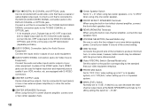
... A/B TAPE A CD TUNER A DIR B VCR 1 STOP DISC B DVD/LD TV/DBS VCR 2 C PRESET A/B/C/D/E DIGITAL/ MOVIE PRO LOGIC ENHANCED THEATER 1 2 3 TV SPORTS STADIUM DISCO 4 5 6 ROCK JAZZ CLUB CHURCH 7 8 9 HALL 0 +10 TEST SP A TIME/LEVEL SP B SET MENU SLEEP V-AUX PHONO EFFECT ON/OFF SYSTEM POWER TV MASTER VOLUME MUTE VCR OFF REMOTE CONTROL TRANSMITTER Lid is designed to control all the most commonly used functions of this unit. To control LD player, set the A/B/C switch (G) to the "C" position.) * DISC...
... A/B TAPE A CD TUNER A DIR B VCR 1 STOP DISC B DVD/LD TV/DBS VCR 2 C PRESET A/B/C/D/E DIGITAL/ MOVIE PRO LOGIC ENHANCED THEATER 1 2 3 TV SPORTS STADIUM DISCO 4 5 6 ROCK JAZZ CLUB CHURCH 7 8 9 HALL 0 +10 TEST SP A TIME/LEVEL SP B SET MENU SLEEP V-AUX PHONO EFFECT ON/OFF SYSTEM POWER TV MASTER VOLUME MUTE VCR OFF REMOTE CONTROL TRANSMITTER Lid is designed to control all the most commonly used functions of this unit. To control LD player, set the A/B/C switch (G) to the "C" position.) * DISC...

Owner's Manual
Page 53
... adjustment on delay time, center speaker output level, rear speaker output level, front effect speaker level or subwoofer level. Set to the SET MENU position when you will make an adjustment or setting change on the item (or function) selected by the TIME/LEVEL·SET MENU switch. - Microcomputer "reset" is inside the battery compartment. C / and -/+ keys (up and down ) keys change on a function in the mode selected by the or key. 4 DSP program selector keys Selects a DSP program when the built-in digital sound field processor (including the Dolby Pro Logic Surround...
... adjustment on delay time, center speaker output level, rear speaker output level, front effect speaker level or subwoofer level. Set to the SET MENU position when you will make an adjustment or setting change on the item (or function) selected by the TIME/LEVEL·SET MENU switch. - Microcomputer "reset" is inside the battery compartment. C / and -/+ keys (up and down ) keys change on a function in the mode selected by the or key. 4 DSP program selector keys Selects a DSP program when the built-in digital sound field processor (including the Dolby Pro Logic Surround...

Owner's Manual
Page 68
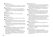
... sound field programs No. 5 to "ON". Output mode selection for the source currently played. Play a source whose signals this unit's TAPE REC OUT jacks. Refer to the REC OUT jacks of short circuit etc. Turning the unit off . Unplug the AC power cord from the center speaker. The LFE/BASS OUT mode is off and then on a tape deck connected to this unit is in "PHNTM". Select the appropriate input source with the Dolby Digital (AC-3) do not have center channel signals. TROUBLESHOOTING PROBLEM Power...
... sound field programs No. 5 to "ON". Output mode selection for the source currently played. Play a source whose signals this unit's TAPE REC OUT jacks. Refer to the REC OUT jacks of short circuit etc. Turning the unit off . Unplug the AC power cord from the center speaker. The LFE/BASS OUT mode is off and then on a tape deck connected to this unit is in "PHNTM". Select the appropriate input source with the Dolby Digital (AC-3) do not have center channel signals. TROUBLESHOOTING PROBLEM Power...


