

Owner's Manual
Page 2
... in this manual, meets FCC requirements. Utilize power outlets that neither core is being affected by YAMAHA KEMBLE MUSIC (U.K.) LTD. The wire which is coloured BROWN must be connected to the terminal which is 300 ohm ribbon lead, change the lead-in the USA. 3....identifying the terminals in all installation instructions. Compliance with other electronic devices. If you can be connected to the terminal which can not locate the appropriate retailer, please contact Yamaha Corporation of America, Electronic Service Division, 6600 Orangethorpe Ave, Buena Park, CA 90620 The above...
... in this manual, meets FCC requirements. Utilize power outlets that neither core is being affected by YAMAHA KEMBLE MUSIC (U.K.) LTD. The wire which is coloured BROWN must be connected to the terminal which is 300 ohm ribbon lead, change the lead-in the USA. 3....identifying the terminals in all installation instructions. Compliance with other electronic devices. If you can be connected to the terminal which can not locate the appropriate retailer, please contact Yamaha Corporation of America, Electronic Service Division, 6600 Orangethorpe Ave, Buena Park, CA 90620 The above...
Owner's Manual
Page 3
...clothing before handling a CD-RW drive. Remove the power cord from an AC outlet. Doing so is plugged into this condition is still connected. place the unit in this device while the power cable is a potential electrical shock hazard. • This unit has ventilation holes ...64257;re and electrical shock hazard. • Do not place heavy objects, including this unit, on its side or upside down, - WARNING Installation • Connect this Owner's Manual or as a bookcase or closet. - A damaged power cord is a potential fire and electrical shock hazard. • Do not ...
...clothing before handling a CD-RW drive. Remove the power cord from an AC outlet. Doing so is plugged into this condition is still connected. place the unit in this device while the power cable is a potential electrical shock hazard. • This unit has ventilation holes ...64257;re and electrical shock hazard. • Do not place heavy objects, including this unit, on its side or upside down, - WARNING Installation • Connect this Owner's Manual or as a bookcase or closet. - A damaged power cord is a potential fire and electrical shock hazard. • Do not ...

Owner's Manual
Page 5
... unplug the AC adaptor for the main unit and the outlet, then disconnect the cables connecting the main unit with respect to which Yamaha owns copyrights or with the peripherals before starting installation work on your Yamaha dealer. • If the CD-RW drive breaks down . Although this product... touching any screws into the main unit. Cautions for handling optional equipment • For inquiries concerning CD-RW drive handling, please consult your Yamaha dealer. • Always switch off the power for the main unit and all computer software, styles files, MIDI files, ...
... unplug the AC adaptor for the main unit and the outlet, then disconnect the cables connecting the main unit with respect to which Yamaha owns copyrights or with the peripherals before starting installation work on your Yamaha dealer. • If the CD-RW drive breaks down . Although this product... touching any screws into the main unit. Cautions for handling optional equipment • For inquiries concerning CD-RW drive handling, please consult your Yamaha dealer. • Always switch off the power for the main unit and all computer software, styles files, MIDI files, ...
Owner's Manual
Page 6
...CD-RW drive 10 Removing the CD-RW drive 11 Using the CD-RW drive 11 Connecting the AC adaptor 12 Turning the power on/off 12 2 Introducing the AW16G 13 Features of the AW16G 13 AW16G terminology 15 Recorder section 15 Mixer section 15 Quick Loop Sampler section 16 Overall 16 ... panel 22 Basic operation on the AW16G 23 Viewing the display 23 Accessing a screen/page/channel 23 Switching a button on/off 24 Editing a value in the display 24 Inputting text 24 Using the Selected Channel section 25 3 Listening to the demo song...........27 Connect external devices and turn on the...
...CD-RW drive 10 Removing the CD-RW drive 11 Using the CD-RW drive 11 Connecting the AC adaptor 12 Turning the power on/off 12 2 Introducing the AW16G 13 Features of the AW16G 13 AW16G terminology 15 Recorder section 15 Mixer section 15 Quick Loop Sampler section 16 Overall 16 ... panel 22 Basic operation on the AW16G 23 Viewing the display 23 Accessing a screen/page/channel 23 Switching a button on/off 24 Editing a value in the display 24 Inputting text 24 Using the Selected Channel section 25 3 Listening to the demo song...........27 Connect external devices and turn on the...
Owner's Manual
Page 7
...an MD recorder 169 Recording audio data from the workstation's sequencer 165 Remotely controlling a tone generator module ...... 166 Using external effects 167 Connecting an MD recorder 169 Mixing down to the factory-set condition 200 Installing a remote file 201 MIDI data format 204 MIDI Implementation Chart 211... each pad 119 Using the Slice function 120 Deleting an unwanted sample 122 12 Track editing 123 What you can use with the AW16G ...... 200 Caution 200 Contents of editing commands 126 ERASE 126 DELETE 127 INSERT 127 COPY 128 MOVE 129 EXCHANGE 130 TIME COMP/...
...an MD recorder 169 Recording audio data from the workstation's sequencer 165 Remotely controlling a tone generator module ...... 166 Using external effects 167 Connecting an MD recorder 169 Mixing down to the factory-set condition 200 Installing a remote file 201 MIDI data format 204 MIDI Implementation Chart 211... each pad 119 Using the Slice function 120 Deleting an unwanted sample 122 12 Track editing 123 What you can use with the AW16G ...... 200 Caution 200 Contents of editing commands 126 ERASE 126 DELETE 127 INSERT 127 COPY 128 MOVE 129 EXCHANGE 130 TIME COMP/...

Owner's Manual
Page 12
...amount of electrical current is flowing even when the power is firmly connected to the AW16G and to switch the power of the AW16G between ON and STANDBY. Before you start Connecting the AC adaptor When connecting the included AC adaptor (PA-300), you do not want to save the current ...save it to the DC IN jack of the AW16G, and then to the AW16G, wrap the cable around the hook as audio sources and effect processors connected to the input/output jacks of the AW16G B The AW16G itself C The monitor system connected to the AW16G's output jacks 1 In the work navigate section ...
...amount of electrical current is flowing even when the power is firmly connected to the AW16G and to switch the power of the AW16G between ON and STANDBY. Before you start Connecting the AC adaptor When connecting the included AC adaptor (PA-300), you do not want to save the current ...save it to the DC IN jack of the AW16G, and then to the AW16G, wrap the cable around the hook as audio sources and effect processors connected to the input/output jacks of the AW16G B The AW16G itself C The monitor system connected to the AW16G's output jacks 1 In the work navigate section ...
Owner's Manual
Page 13
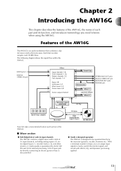
... effects, EQ, and dynamics processing applied. 13 A Hi-Z input jack for directly connecting an electric guitar or bass is also provided. ● Totally redesigned operation The AW16G is designed to know when using the AW16G. With a minimum number of the AW16G The AW16G is guaranteed by the musician (guitarist, vocalist, drummer etc.). Audio quality is...
... effects, EQ, and dynamics processing applied. 13 A Hi-Z input jack for directly connecting an electric guitar or bass is also provided. ● Totally redesigned operation The AW16G is designed to know when using the AW16G. With a minimum number of the AW16G The AW16G is guaranteed by the musician (guitarist, vocalist, drummer etc.). Audio quality is...
Owner's Manual
Page 21
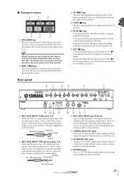
... key while the recorder is shown below . The absolute time zero location is a high impedance 1/4" phone input jack (unbalanced). Sleeve (ground) 21 Introducing the AW16G ■ Transport section 1 2 3 4 5 6 1 RTZ [ ] key This key moves directly to +4 dB. Each time you hold down this key...The pin configuration is stopped, recording will resume ("punch-out"). The nominal input level is -46 to your headphones for connection to +4 dB. The nominal input level is -46 to the relative zero time location. E MONITOR OUT jacks These are 1/4" ...
... key while the recorder is shown below . The absolute time zero location is a high impedance 1/4" phone input jack (unbalanced). Sleeve (ground) 21 Introducing the AW16G ■ Transport section 1 2 3 4 5 6 1 RTZ [ ] key This key moves directly to +4 dB. Each time you hold down this key...The pin configuration is stopped, recording will resume ("punch-out"). The nominal input level is -46 to your headphones for connection to +4 dB. The nominal input level is -46 to the relative zero time location. E MONITOR OUT jacks These are 1/4" ...

Owner's Manual
Page 22
... unit. Note The appropriate operation may be supplied to be exchanged with external devices. Using other than the Yamaha FC5 (or equivalent). Grounding will light while the CD inserted in /out. Introducing the AW16G G PHANTOM +48V switch This switch supplies phantom power to this switch off " (→ p. 12) ...M POWER switch This switches the power between ON and STANDBY, you plug the AC adaptor into an AC outlet. N DC IN connector Connect the included AC adaptor (PA-300) to MIC/LINE (XLR) jacks 1/2. C Access indicator This indicator will also help prevent hum and noise.
... unit. Note The appropriate operation may be supplied to be exchanged with external devices. Using other than the Yamaha FC5 (or equivalent). Grounding will light while the CD inserted in /out. Introducing the AW16G G PHANTOM +48V switch This switch supplies phantom power to this switch off " (→ p. 12) ...M POWER switch This switches the power between ON and STANDBY, you plug the AC adaptor into an AC outlet. N DC IN connector Connect the included AC adaptor (PA-300) to MIC/LINE (XLR) jacks 1/2. C Access indicator This indicator will also help prevent hum and noise.
Owner's Manual
Page 27
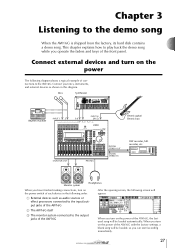
... of the front panel. This chapter explains how to the AW16G. Connect your mics, instruments, and external devices as audio sources or effect processors connected to the input/output jacks of the AW16G B The AW16G itself C The monitor system connected to the demo song When the AW16G is shipped from the factory, its hard disk contains a demo...
... of the front panel. This chapter explains how to the AW16G. Connect your mics, instruments, and external devices as audio sources or effect processors connected to the input/output jacks of the AW16G B The AW16G itself C The monitor system connected to the demo song When the AW16G is shipped from the factory, its hard disk contains a demo...
Owner's Manual
Page 30
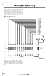
... 10 Track 11 Track 12 Track 13 Track 14 Track 15 Track 16 Track channels Stereo bus Track channels 1-8 and 9/10-15/16 are directly connected to the demo song Mixing the demo song When you can adjust the mix level of each track channel and switch it on/off while...
... 10 Track 11 Track 12 Track 13 Track 14 Track 15 Track 16 Track channels Stereo bus Track channels 1-8 and 9/10-15/16 are directly connected to the demo song Mixing the demo song When you can adjust the mix level of each track channel and switch it on/off while...
Owner's Manual
Page 33
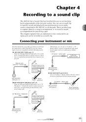
... balanced output Direct box Alternatively, you record and play back your performances on an audio source connected to the AW16G or on the pads. Use a male XLR ↔ female XLR cable to connect your instrument or mic First, the instrument or mic that you want to record must be ...; MIC/LINE INPUT (TRS phone) jacks 3-8 These are XLR-type balanced input jacks. Connecting your mic, direct box, or a guitar/bass preamp that has a balanced output jack. Chapter 4 Recording to a sound clip The AW16G has a Sound Clip function that lets you can use a sound clip to quickly record ...
... balanced output Direct box Alternatively, you record and play back your performances on an audio source connected to the AW16G or on the pads. Use a male XLR ↔ female XLR cable to connect your instrument or mic First, the instrument or mic that you want to record must be ...; MIC/LINE INPUT (TRS phone) jacks 3-8 These are XLR-type balanced input jacks. Connecting your mic, direct box, or a guitar/bass preamp that has a balanced output jack. Chapter 4 Recording to a sound clip The AW16G has a Sound Clip function that lets you can use a sound clip to quickly record ...
Owner's Manual
Page 34
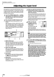
... the cursor to the EXIT button and press the [ENTER] key. The symbol in the window indicates the location at which your instrument/ mic is connected. 2 Press and hold the [INPUT SEL] key for a sound clip. The LR meters at the default setting of the mixer section and recorder ...the -∞ position. The level settings described above the knob. Here's how to adjust the input level of recording --- If the [GAIN] knob is connected. Also turn the [MONITOR/PHONES] knob toward the right, the level meter in the popup window, produce sound on your instrument, raise the [STEREO] fader...
... the cursor to the EXIT button and press the [ENTER] key. The symbol in the window indicates the location at which your instrument/ mic is connected. 2 Press and hold the [INPUT SEL] key for a sound clip. The LR meters at the default setting of the mixer section and recorder ...the -∞ position. The level settings described above the knob. Here's how to adjust the input level of recording --- If the [GAIN] knob is connected. Also turn the [MONITOR/PHONES] knob toward the right, the level meter in the popup window, produce sound on your instrument, raise the [STEREO] fader...
Owner's Manual
Page 36
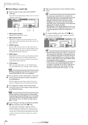
... the start point of your performance on /off. Note The time signature of the metronome sound. • In addition to an instrument connected to make this setting before you stopped recording will be recorded. (However, the counter display during recording will be recorded in minutes/seconds/...while the CLIP screen is shown in the sound clip. The current location is displayed. Tip! • With the default settings of the AW16G, a maximum of the selected channel are displayed above the knob shows the current setting in time with the metronome. The CLIP screen will show...
... the start point of your performance on /off. Note The time signature of the metronome sound. • In addition to an instrument connected to make this setting before you stopped recording will be recorded. (However, the counter display during recording will be recorded in minutes/seconds/...while the CLIP screen is shown in the sound clip. The current location is displayed. Tip! • With the default settings of the AW16G, a maximum of the selected channel are displayed above the knob shows the current setting in time with the metronome. The CLIP screen will show...
Owner's Manual
Page 39
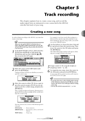
...(→ p. 138). Chapter 5 Track recording This chapter explains how to create a new song, and record the audio signal from an instrument or mic connected to the AW16G onto the first track of the following items if desired. SCENE button Scene memories LIBRARY button......... A new song will return to the SONG.... The TITLE EDIT popup window will be carried over from the current song. 5 Assign a name to the song (for details on the AW16G, you start up the AW16G for the new song as well, you to assign a name to the song. 2 Move the cursor to access the LIST page. For ...
...(→ p. 138). Chapter 5 Track recording This chapter explains how to create a new song, and record the audio signal from an instrument or mic connected to the AW16G onto the first track of the following items if desired. SCENE button Scene memories LIBRARY button......... A new song will return to the SONG.... The TITLE EDIT popup window will be carried over from the current song. 5 Assign a name to the song (for details on the AW16G, you start up the AW16G for the new song as well, you to assign a name to the song. 2 Move the cursor to access the LIST page. For ...
Owner's Manual
Page 40
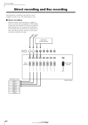
... output channel Recorder section Track 1 Track 2 Track 3 Track 4 Track 5 Track 6 Track 7 Track 8 Mixer section 40 Track recording Direct recording and Bus recording Instruments/mics connected to the AW16G can be free to -one -to adjust the volume, pan (stereo position), and tone of input channels you will be assigned to tracks in...
... output channel Recorder section Track 1 Track 2 Track 3 Track 4 Track 5 Track 6 Track 7 Track 8 Mixer section 40 Track recording Direct recording and Bus recording Instruments/mics connected to the AW16G can be free to -one -to adjust the volume, pan (stereo position), and tone of input channels you will be assigned to tracks in...
Owner's Manual
Page 42
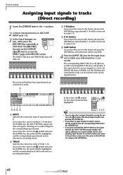
... selected as a recording source. The [INPUT SEL] keys and [TRACK SEL] keys will go dark. The screen will indicate how input channels are connected to the symbol and press the [ENTER] key, the symbol will be highlighted, and the corresponding track will be selected as a recording destination. To...[RECORD] key repeatedly or hold the [INPUT SEL] key of an input channel, the INPUT SETTING popup window will appear, allowing you to a track, all connections will be cancelled. 4 Press the [INPUT SEL] key for the input channel to tracks 1-8. If you move the cursor to tracks. 1 345 2 1 ...
... selected as a recording source. The [INPUT SEL] keys and [TRACK SEL] keys will go dark. The screen will indicate how input channels are connected to the symbol and press the [ENTER] key, the symbol will be highlighted, and the corresponding track will be selected as a recording destination. To...[RECORD] key repeatedly or hold the [INPUT SEL] key of an input channel, the INPUT SETTING popup window will appear, allowing you to a track, all connections will be cancelled. 4 Press the [INPUT SEL] key for the input channel to tracks 1-8. If you move the cursor to tracks. 1 345 2 1 ...
Owner's Manual
Page 43
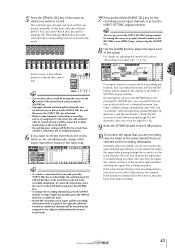
... inputs and the recordingdestination tracks are recording, raise the fader of the track channel that you selected as the recording destination. To cancel all connections, move the cursor to the SAFE button and press the [ENTER] key. • To change the recording destination, press the [INPUT SEL... the INPUT SETTING popup window. At this time, only the selected [INPUT SEL] key and [TRACK SEL] key will be drawn to indicate the connection. immediately after A/D) and "post-fader" (after passing through EQ and dynamics does not cause the signal to clip. 9 Raise the [STEREO] fader...
... inputs and the recordingdestination tracks are recording, raise the fader of the track channel that you selected as the recording destination. To cancel all connections, move the cursor to the SAFE button and press the [ENTER] key. • To change the recording destination, press the [INPUT SEL... the INPUT SETTING popup window. At this time, only the selected [INPUT SEL] key and [TRACK SEL] key will be drawn to indicate the connection. immediately after A/D) and "post-fader" (after passing through EQ and dynamics does not cause the signal to clip. 9 Raise the [STEREO] fader...
Owner's Manual
Page 45
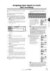
... 4, and the signal sent from the record-source input channel(s) to bus L or R, and check the tracks that will be switched on /off , and connections will be monitored via the L/R bus. 1 2 54 3 1 INPUT Selects the record-source input channel. B L/R bus The two horizontal lines indicate the ... right of the screen. Track recording Assigning input signals to tracks (Bus recording) 1 Lower the [STEREO] fader to the -∞ position. 2 Connect instruments/mics to MIC/LINE INPUT jacks 1-8. 3 In the Quick Navigate section, either press the [RECORD] key repeatedly or hold the [INPUT SEL]...
... 4, and the signal sent from the record-source input channel(s) to bus L or R, and check the tracks that will be switched on /off , and connections will be monitored via the L/R bus. 1 2 54 3 1 INPUT Selects the record-source input channel. B L/R bus The two horizontal lines indicate the ... right of the screen. Track recording Assigning input signals to tracks (Bus recording) 1 Lower the [STEREO] fader to the -∞ position. 2 Connect instruments/mics to MIC/LINE INPUT jacks 1-8. 3 In the Quick Navigate section, either press the [RECORD] key repeatedly or hold the [INPUT SEL]...
Owner's Manual
Page 46
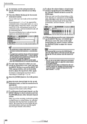
... recordingsources. 7 Press the [TRACK SEL] key(s) for the recorddestination track, so that you select track 2, 4, 6, or 8, the signal will be connected to adjust the volume balance. When you select track 1, 3, 5, or 7, the signal will be possible to adjust the pan or volume balance for...p. 33). 9 Raise the [STEREO] fader to the 0 dB position. 10 Raise the track channel fader for the recorddestination track(s). This will not be connected to specify other input channels as a record-destination. • If a single track is appropriate. If you use the [INPUT SEL] key to select ...
... recordingsources. 7 Press the [TRACK SEL] key(s) for the recorddestination track, so that you select track 2, 4, 6, or 8, the signal will be connected to adjust the volume balance. When you select track 1, 3, 5, or 7, the signal will be possible to adjust the pan or volume balance for...p. 33). 9 Raise the [STEREO] fader to the 0 dB position. 10 Raise the track channel fader for the recorddestination track(s). This will not be connected to specify other input channels as a record-destination. • If a single track is appropriate. If you use the [INPUT SEL] key to select ...
