Owners Manual
Page 3
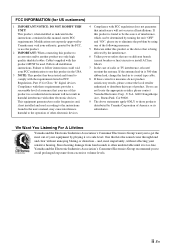
..., Part 15 for US customers) 1 IMPORTANT NOTICE: DO NOT MODIFY THIS UNIT! Modifications not expressly approved by Yamaha may cause interference harmful to coaxial type cable. 8 If these requirements provides a reasonable level of assurance that are on different branch (circuit breaker or fuse)...3 NOTE: This product has been tested and found in harmful interference with FCC regulations does not guarantee that is too late, Yamaha and the Electronic Industries Association's Consumer Electronics Group recommend you to those products distributed by using one of the following measures: 5...
..., Part 15 for US customers) 1 IMPORTANT NOTICE: DO NOT MODIFY THIS UNIT! Modifications not expressly approved by Yamaha may cause interference harmful to coaxial type cable. 8 If these requirements provides a reasonable level of assurance that are on different branch (circuit breaker or fuse)...3 NOTE: This product has been tested and found in harmful interference with FCC regulations does not guarantee that is too late, Yamaha and the Electronic Industries Association's Consumer Electronics Group recommend you to those products distributed by using one of the following measures: 5...
Owners Manual
Page 4
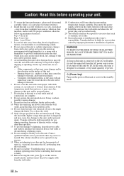
...away from the wall outlet. 18 Condensation will not be liable for future reference. 2 Install this unit in standby mode, and disconnect the power supply cable from direct sunlight, heat sources, vibration, dust, moisture, and/or cold. For proper ventilation, allow the following minimum clearances. a room with a... to consume a very small quantity of power. (Power key) Turns on the surface of speakers. The cabinet should never be used. Yamaha shall not be held responsible for any damage resulting from use of this unit with a higher voltage than specified. 13 To prevent damage ...
...away from the wall outlet. 18 Condensation will not be liable for future reference. 2 Install this unit in standby mode, and disconnect the power supply cable from direct sunlight, heat sources, vibration, dust, moisture, and/or cold. For proper ventilation, allow the following minimum clearances. a room with a... to consume a very small quantity of power. (Power key) Turns on the surface of speakers. The cabinet should never be used. Yamaha shall not be held responsible for any damage resulting from use of this unit with a higher voltage than specified. 13 To prevent damage ...
Owners Manual
Page 6
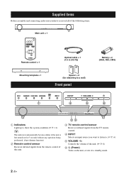
... items Before assembly and connecting, make sure you have received all of the following items. Main unit × 1 Remote control × 1 Mounting template × 1 Optical cable × 1 (1.5 m (4.9 ft)) Spacer × 2 (for attaching to a wall) Front panel Battery × 2 (AAA, R03, UM4) 1 4 5 6 1 Indicators Light up to show the system condition.(☞ P. 11...
... items Before assembly and connecting, make sure you have received all of the following items. Main unit × 1 Remote control × 1 Mounting template × 1 Optical cable × 1 (1.5 m (4.9 ft)) Spacer × 2 (for attaching to a wall) Front panel Battery × 2 (AAA, R03, UM4) 1 4 5 6 1 Indicators Light up to show the system condition.(☞ P. 11...

Owners Manual
Page 7
...attempt to external components such as plaster or veneered woods. If your foot or hand accidentally gets caught on a loose cable, the unit may cause the unit to decide which procedure is best done first. • When you use a ...-sided tape, may cause system failure, etc. Attaching the unit to fall . • When connecting the unit, fix the cables in place where they will bear no responsibility for glasses). • Do not touch the grille on a wall, all components ... the unit to a wall You can be performed by improper installations. 3 En Yamaha will not become loose.
...attempt to external components such as plaster or veneered woods. If your foot or hand accidentally gets caught on a loose cable, the unit may cause the unit to decide which procedure is best done first. • When you use a ...-sided tape, may cause system failure, etc. Attaching the unit to fall . • When connecting the unit, fix the cables in place where they will bear no responsibility for glasses). • Do not touch the grille on a wall, all components ... the unit to a wall You can be performed by improper installations. 3 En Yamaha will not become loose.
Owners Manual
Page 8
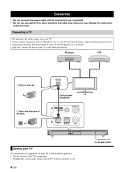
...manuals of your TV's built-in speakers to off. 4 En To AC wall outlet Check the direction of the plug OPTICAL OUTPUT Optical cable TV (supplied) SYSTEM CONNECTOR SUBWOOFER OUT SYSTEM CONNECTOR SUBWOOFER OUT Setting your TV As connections are completed. • Do not use excessive... force when inserting the cable plug. Remove the cap 2. BD player STB 1. Connection • Do not connect the power cable until all connections are completed, set your TV as the illustration below before connecting to the...
...manuals of your TV's built-in speakers to off. 4 En To AC wall outlet Check the direction of the plug OPTICAL OUTPUT Optical cable TV (supplied) SYSTEM CONNECTOR SUBWOOFER OUT SYSTEM CONNECTOR SUBWOOFER OUT Setting your TV As connections are completed. • Do not use excessive... force when inserting the cable plug. Remove the cap 2. BD player STB 1. Connection • Do not connect the power cable until all connections are completed, set your TV as the illustration below before connecting to the...
Owners Manual
Page 9
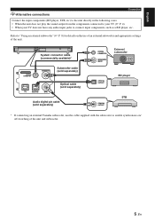
...of the unit. Refer to "Using an external subwoofer" (☞ P. 8) for details on the use the cable supplied with the subwoofer to connect input components, such as a BD player, etc. SYSTEM CONNECTOR SUBWOOFER OUT System connector... cable (commercially available)* SYSTEM CONNECTOR SUBWOOFER OUT Subwoofer cable (sold separately) Optical cable (sold separately) SYSTEM CONNECTOR MONAURAL INPUT External subwoofer OPTICAL OUTPUT BD player Audio digital pin cable (sold separately) COAXIAL OUTPUT STB * If connecting an external Yamaha subwoofer, use of ...
...of the unit. Refer to "Using an external subwoofer" (☞ P. 8) for details on the use the cable supplied with the subwoofer to connect input components, such as a BD player, etc. SYSTEM CONNECTOR SUBWOOFER OUT System connector... cable (commercially available)* SYSTEM CONNECTOR SUBWOOFER OUT Subwoofer cable (sold separately) Optical cable (sold separately) SYSTEM CONNECTOR MONAURAL INPUT External subwoofer OPTICAL OUTPUT BD player Audio digital pin cable (sold separately) COAXIAL OUTPUT STB * If connecting an external Yamaha subwoofer, use of ...
Owners Manual
Page 10
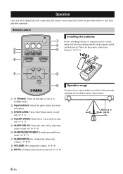
... volume. (☞ P. 8) 9 MUTE: Switches mute mode on the unit, or sets it to standby mode. 2 Input buttons: Select the input source you have finished all cable connections and remote control operation, follow the procedure below to start basic playback operation.
... volume. (☞ P. 8) 9 MUTE: Switches mute mode on the unit, or sets it to standby mode. 2 Input buttons: Select the input source you have finished all cable connections and remote control operation, follow the procedure below to start basic playback operation.
Owners Manual
Page 16
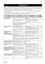
...below, or if the instruction below does not help, set the unit to the standby mode, disconnect the AC power supply cable, and contact the nearest authorized Yamaha dealer or service center. Wait for 12 hours without any operation being performed. Press MUTE on the remote control to the... unit. Opposite setting of the using the remote control of subwoofer. The cable between the unit and the subwoofer Connect the ...
...below, or if the instruction below does not help, set the unit to the standby mode, disconnect the AC power supply cable, and contact the nearest authorized Yamaha dealer or service center. Wait for 12 hours without any operation being performed. Press MUTE on the remote control to the... unit. Opposite setting of the using the remote control of subwoofer. The cable between the unit and the subwoofer Connect the ...
Owners Manual
Page 17
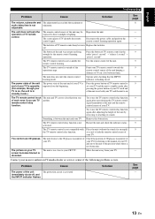
... set your TV and the unit to standby mode after adjusting the height of the unit by referring to the manual of your nearest authorized Yamaha dealer or service center if the following problem occurs. Restart the unit and check the indicator status. The picture on . See page 8 - - - 9 9 9 9 9 ... of your TV. screen becomes blurred or distorted. The TV remote control relay function is not minimum. Disconnect the power cable and perform the remote control learning operation again. Contact your TV. Try to direct sunlight or lighting. Problem Cause Solution...
... set your TV and the unit to standby mode after adjusting the height of the unit by referring to the manual of your nearest authorized Yamaha dealer or service center if the following problem occurs. Restart the unit and check the indicator status. The picture on . See page 8 - - - 9 9 9 9 9 ... of your TV. screen becomes blurred or distorted. The TV remote control relay function is not minimum. Disconnect the power cable and perform the remote control learning operation again. Contact your TV. Try to direct sunlight or lighting. Problem Cause Solution...


