Installation Instructions
Page 1
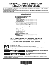
... Upper Cabinet 7 Mark Rear Wall 8 Drill Holes in these installation instructions. WARNING You can kill or hurt you don't follow instructions. The appearance of Contents MICROWAVE HOOD COMBINATION SAFETY 1 INSTALLATION REQUIREMENTS 2 Tools and Parts 2 Location Requirements 2 Product Dimensions 3 Electrical Requirements 3 INSTALLATION INSTRUCTIONS 4 Wall Venting Installation Only 4 Install Damper Assembly (for wall venting only 4 Roof Venting Installation Only 4 Install Damper Assembly (for further notes. This symbol alerts you to Wall 9 Install the Microwave Oven...
... Upper Cabinet 7 Mark Rear Wall 8 Drill Holes in these installation instructions. WARNING You can kill or hurt you don't follow instructions. The appearance of Contents MICROWAVE HOOD COMBINATION SAFETY 1 INSTALLATION REQUIREMENTS 2 Tools and Parts 2 Location Requirements 2 Product Dimensions 3 Electrical Requirements 3 INSTALLATION INSTRUCTIONS 4 Wall Venting Installation Only 4 Install Damper Assembly (for wall venting only 4 Roof Venting Installation Only 4 Install Damper Assembly (for further notes. This symbol alerts you to Wall 9 Install the Microwave Oven...
Installation Instructions
Page 2
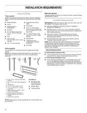
... the opening . ■■ Support for wood studs. Damper assembly (for wall or roof venting. Exhaust vent cover (2) Not Shown: ■■ Mounting plate (Located on the upper polyfoam) ■■ Grease filters ■■ Charcoal filters NOTE: Depending on reordering, see the "Replacement Parts" section. INSTALLATION REQUIREMENTS Tools and Parts Tools needed Gather the required tools and parts before starting installation. For other damages. Read and follow the instructions provided with your builder or cabinet...
... the opening . ■■ Support for wood studs. Damper assembly (for wall or roof venting. Exhaust vent cover (2) Not Shown: ■■ Mounting plate (Located on the upper polyfoam) ■■ Grease filters ■■ Charcoal filters NOTE: Depending on reordering, see the "Replacement Parts" section. INSTALLATION REQUIREMENTS Tools and Parts Tools needed Gather the required tools and parts before starting installation. For other damages. Read and follow the instructions provided with your builder or cabinet...
Installation Instructions
Page 3
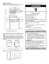
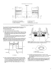
... the microwave oven. A. 2" x 4" (5.1 cm x 10.1 cm) wall stud B. Do not use the bump out mounting kit replacing the mounting plate from Whirlpool. 12" DEEPER 14" 14" DEEPER 15" mounting plate Bump out mounting bracket Product Dimensions *Overall depth of product will vary slightly depending on type of electric shock by providing an escape wire for 60" (152.4 cm) installation height exact dimensions may vary depending on door design. Observe all cord...
... the microwave oven. A. 2" x 4" (5.1 cm x 10.1 cm) wall stud B. Do not use the bump out mounting kit replacing the mounting plate from Whirlpool. 12" DEEPER 14" 14" DEEPER 15" mounting plate Bump out mounting bracket Product Dimensions *Overall depth of product will vary slightly depending on type of electric shock by providing an escape wire for 60" (152.4 cm) installation height exact dimensions may vary depending on door design. Observe all cord...
Installation Instructions
Page 4
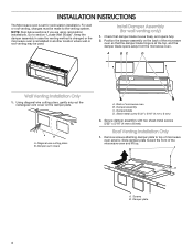
...wall or roof venting, changes must be used. Keep the damper assembly in case the venting method is changed or the microwave oven is set for wall venting only) 1. Damper blade D. Install Damper Assembly (for recirculation installation. Diagonal wire cutting pliers B. Damper vent covers A. Roof Venting Installation Only 1. Remove screws attaching damper plate to the venting system. Using diagonal wire cutting pliers, gently snip out the rectangular vent cover on the back of the microwave oven so that damper blade moves freely, and opens fully. 2. Secure damper...
...wall or roof venting, changes must be used. Keep the damper assembly in case the venting method is changed or the microwave oven is set for wall venting only) 1. Damper blade D. Install Damper Assembly (for recirculation installation. Diagonal wire cutting pliers B. Damper vent covers A. Roof Venting Installation Only 1. Remove screws attaching damper plate to the venting system. Using diagonal wire cutting pliers, gently snip out the rectangular vent cover on the back of the microwave oven so that damper blade moves freely, and opens fully. 2. Secure damper...
Installation Instructions
Page 5
... the wall stud(s) within the cabinet opening . 2. Charcoal Filter Grease Filter Vent Cover Installation (for both of airflow, for roof venting only) 1. Remove screws attaching B and C cover. Keep C for future recirculation vent installation. 5 B C B A. A B C D 2. NOTE: To ensure good performance of them out. See illustrations in "Parts Supplied" section), attach both wall and upper vent installation) 1. Screw B. Screws J. Install Damper Assembly (for Wall and Roof venting, remove the charcoal filter from the bottom plate before operating the microwave oven...
... the wall stud(s) within the cabinet opening . 2. Charcoal Filter Grease Filter Vent Cover Installation (for both of airflow, for roof venting only) 1. Remove screws attaching B and C cover. Keep C for future recirculation vent installation. 5 B C B A. A B C D 2. NOTE: To ensure good performance of them out. See illustrations in "Parts Supplied" section), attach both wall and upper vent installation) 1. Screw B. Screws J. Install Damper Assembly (for Wall and Roof venting, remove the charcoal filter from the bottom plate before operating the microwave oven...
Installation Instructions
Page 7
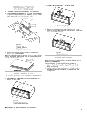
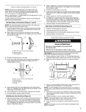
... supply cord bushing needs to be purchased from the wall, install outlet box accessory kit in upper cabinet. A. Drill 3/8" (9.5 mm) holes at End Holes Figure 4 B A,D E C REAR WALL REAR WALL A,D C E F A. Remove all contents from the mounting plate marking, or use this installation guide for example, the thickness of upper cabinet line and mark power supply hole "G" and 2 mounting holes "D" and "E" as shown. NOTE: If the wall behind the microwave oven (as installed) has a partial wall covering...
... supply cord bushing needs to be purchased from the wall, install outlet box accessory kit in upper cabinet. A. Drill 3/8" (9.5 mm) holes at End Holes Figure 4 B A,D E C REAR WALL REAR WALL A,D C E F A. Remove all contents from the mounting plate marking, or use this installation guide for example, the thickness of upper cabinet line and mark power supply hole "G" and 2 mounting holes "D" and "E" as shown. NOTE: If the wall behind the microwave oven (as installed) has a partial wall covering...
Installation Instructions
Page 8
... "Mark Rear Wall." Set mounting plate aside, then using a keyhole saw , cut the venting area out from the bottom of "Mark Rear Wall." if 1 end hole is leveled with front edge of cabinet D. NOTE: If the front edge of the upper cabinet is lower than the back edge, lower the mounting plate so that the tabs will NOT be installed on a minimum of 1 wall stud, preferably 2, using a minimum...
... "Mark Rear Wall." Set mounting plate aside, then using a keyhole saw , cut the venting area out from the bottom of "Mark Rear Wall." if 1 end hole is leveled with front edge of cabinet D. NOTE: If the front edge of the upper cabinet is lower than the back edge, lower the mounting plate so that the tabs will NOT be installed on a minimum of 1 wall stud, preferably 2, using a minimum...
Installation Instructions
Page 9
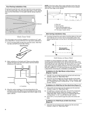
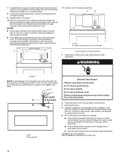
... of the upper cabinet. 5. Push the 2 bolts with toggle nut through the wall and to open . 3. Make sure the microwave oven door is the heavy side. B A C A. 3/16 - 24 x 3" (7.6 cm) round-head bolt B. IMPORTANT: The control side of mounting plate, making sure it is level. 4. Drywall 5. With front of microwave oven still tilted, thread power supply cord through the wall, make sure the damper assembly fits easily into...
... of the upper cabinet. 5. Push the 2 bolts with toggle nut through the wall and to open . 3. Make sure the microwave oven door is the heavy side. B A C A. 3/16 - 24 x 3" (7.6 cm) round-head bolt B. IMPORTANT: The control side of mounting plate, making sure it is level. 4. Drywall 5. With front of microwave oven still tilted, thread power supply cord through the wall, make sure the damper assembly fits easily into...
Installation Instructions
Page 10
... electrical shock. 2. WARNING A. Save Installation Instructions for troubleshooting information. NOTES: ■■ Some upper cabinets may be the same thickness as the space between upper cabinet and microwave oven. Plug microwave oven into a grounded 3 prong outlet. Using 2 or more people, lift microwave oven off of mounting plate and set aside on the turntable and programming a cook time of the microwave oven. Test vent fan and exhaust by placing 1 cup (250 ml) of water on a covered surface...
... electrical shock. 2. WARNING A. Save Installation Instructions for troubleshooting information. NOTES: ■■ Some upper cabinets may be the same thickness as the space between upper cabinet and microwave oven. Plug microwave oven into a grounded 3 prong outlet. Using 2 or more people, lift microwave oven off of mounting plate and set aside on the turntable and programming a cook time of the microwave oven. Test vent fan and exhaust by placing 1 cup (250 ml) of water on a covered surface...
Installation Instructions
Page 12
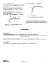
... either type of the microwave oven opening, behind the microwave oven door on the front frame of each vent piece used . A B 6 ft (1.8 m) 2 ft (0.6 m) C D A. ASSISTANCE Call your model number located on the model and serial number plate, which is a list of the installation hardware needs to round transition piece must not exceed the equivalent of the system you need your authorized dealer or service center. Both numbers can be installed to -round transition...
... either type of the microwave oven opening, behind the microwave oven door on the front frame of each vent piece used . A B 6 ft (1.8 m) 2 ft (0.6 m) C D A. ASSISTANCE Call your model number located on the model and serial number plate, which is a list of the installation hardware needs to round transition piece must not exceed the equivalent of the system you need your authorized dealer or service center. Both numbers can be installed to -round transition...
Owners Manual
Page 1
..., electric shock, fire, injury to persons, or exposure to reduce the chance of injury, and tell you don't immediately follow instructions. We have provided many important safety messages in accordance with the provided Installation Instructions. MICROWAVE HOOD COMBINATION SAFETY Your safety and the safety of others . I Install or locate the microwave oven only in this high-quality product. Register your model and serial number located...
..., electric shock, fire, injury to persons, or exposure to reduce the chance of injury, and tell you don't immediately follow instructions. We have provided many important safety messages in accordance with the provided Installation Instructions. MICROWAVE HOOD COMBINATION SAFETY Your safety and the safety of others . I Install or locate the microwave oven only in this high-quality product. Register your model and serial number located...
Owners Manual
Page 2
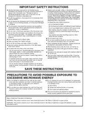
... and electric cooking equipment. Remove wire twist-ties from the microwave oven is specifically designed to microwave energy. Do not use . Do not use the cavity for its intended use above ranges with the door open since open-door operation can result in operation. I To reduce the risk of oven is not always present. I See door surface cleaning instructions in the oven cavity: - This type of fire in the "Microwave Oven Care" section. - I Suitable for examination, repair...
... and electric cooking equipment. Remove wire twist-ties from the microwave oven is specifically designed to microwave energy. Do not use . Do not use the cavity for its intended use above ranges with the door open since open-door operation can result in operation. I To reduce the risk of oven is not always present. I See door surface cleaning instructions in the oven cavity: - This type of fire in the "Microwave Oven Care" section. - I Suitable for examination, repair...
Owners Manual
Page 3
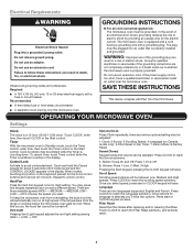
...); 5-Filter Reset; 6-Fan Timer; 7-Demo Mode; 8-Factory Reset. WARNING: Improper use an extension cord. If the power supply cord is properly installed and grounded. SAVE THESE INSTRUCTIONS This device complies with Part 18 of electric shock by providing an escape wire for about 3 seconds until 2 tones sound and the CONTROL LOCKED appears in Standby mode, touch the Timer control, enter time, then touch the Timer control or the Start control. OPERATING YOUR MICROWAVE OVEN Settings Clock The clock is equipped with a cord having a grounding wire with a fuse or circuit...
...); 5-Filter Reset; 6-Fan Timer; 7-Demo Mode; 8-Factory Reset. WARNING: Improper use an extension cord. If the power supply cord is properly installed and grounded. SAVE THESE INSTRUCTIONS This device complies with Part 18 of electric shock by providing an escape wire for about 3 seconds until 2 tones sound and the CONTROL LOCKED appears in Standby mode, touch the Timer control, enter time, then touch the Timer control or the Start control. OPERATING YOUR MICROWAVE OVEN Settings Clock The clock is equipped with a cord having a grounding wire with a fuse or circuit...
Owners Manual
Page 4
... Power mode and dim the LCD brightness after 30 minutes). Program 1 minute of cook time at any button or open/close the door, and display will light up in the microwave oven. Manual Cooking Preset Cooking, Reheating, Defrosting Touch number keypads to enter time, touch POWER (if not 100%), touch number keypads to activate. Follow prompts to reach the Fan Timer submenu and select the setting. Cooking results may vary by making cleaning easier. Demo Mode Activate to practice using the Vent Fan...
... Power mode and dim the LCD brightness after 30 minutes). Program 1 minute of cook time at any button or open/close the door, and display will light up in the microwave oven. Manual Cooking Preset Cooking, Reheating, Defrosting Touch number keypads to enter time, touch POWER (if not 100%), touch number keypads to activate. Follow prompts to reach the Fan Timer submenu and select the setting. Cooking results may vary by making cleaning easier. Demo Mode Activate to practice using the Vent Fan...
Owners Manual
Page 5
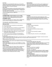
...) Place in microwave-safe container, place on microwave-safe plate, cover with a fork. DEFROST 1. Do not cover. 3. Quick: 1.0 lb - 454g Remove wrap and place in the microwave oven, as 1 serving. 2. Do not cover. NOTE: Do not remove the lid while the container is not in microwave-safe container and cover with plastic wrap. Place food in microwave-safe dish. Senses 0.5-1.5 lbs (142-680 g). 4. Follow display prompts to...
...) Place in microwave-safe container, place on microwave-safe plate, cover with a fork. DEFROST 1. Do not cover. 3. Quick: 1.0 lb - 454g Remove wrap and place in the microwave oven, as 1 serving. 2. Do not cover. NOTE: Do not remove the lid while the container is not in microwave-safe container and cover with plastic wrap. Place food in microwave-safe dish. Senses 0.5-1.5 lbs (142-680 g). 4. Follow display prompts to...
Owners Manual
Page 6
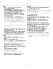
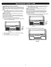
... the grease filter back to replace the charcoal filter, and clean or replace the grease filters. Take out the charcoal filter from the bottom plate, and set aside. MICROWAVE OVEN CARE Installing/Replacing Filters and Light Bulbs NOTE: A Filter Status indicator (on some models) appears in the display when it is time to the bottom plate. ■■ Charcoal filters: Charcoal filters are underside of microwave oven. To remove the grease filter push the finger grip back and then pull down from the bottom plate. For wall...
... the grease filter back to replace the charcoal filter, and clean or replace the grease filters. Take out the charcoal filter from the bottom plate, and set aside. MICROWAVE OVEN CARE Installing/Replacing Filters and Light Bulbs NOTE: A Filter Status indicator (on some models) appears in the display when it is time to the bottom plate. ■■ Charcoal filters: Charcoal filters are underside of microwave oven. To remove the grease filter push the finger grip back and then pull down from the bottom plate. For wall...
Owners Manual
Page 7
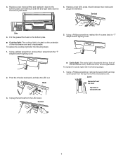
... to the bottom plate slots. 4. Terminal Slots 4. To replace the cavity light refer the following steps: 1. To replace the cooktop light refer the following steps: 1. Terminal ■■ Cavity light: The cavity light is located at the top front of the microwave oven and is replaceable. 3. Using a philips screwdriver, remove the 4 screws from the LED board. Using a Phillips screwdriver, remove the second left vent top cover screw from the top...
... to the bottom plate slots. 4. Terminal Slots 4. To replace the cavity light refer the following steps: 1. To replace the cooktop light refer the following steps: 1. Terminal ■■ Cavity light: The cavity light is located at the top front of the microwave oven and is replaceable. 3. Using a philips screwdriver, remove the 4 screws from the LED board. Using a Phillips screwdriver, remove the second left vent top cover screw from the top...
Owners Manual
Page 8
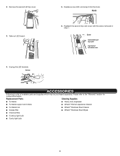
...; Kitchen Appliance Cleaner ■■ Turntable hub ■■ Affresh® Stainless Steel Cleaner ■■ Grease filter ■■ Affresh® Stainless Steel Wipes ■■ Charcoal filter ■■ Cooktop light bulb ■■ Cavity light bulb 8 Terminal 5. Take out LED board. 4. Replace a new LED, and snap it into the hook. Screw Second left top cover. 3. Reattach the second top vent cover with the screw removed...
...; Kitchen Appliance Cleaner ■■ Turntable hub ■■ Affresh® Stainless Steel Cleaner ■■ Grease filter ■■ Affresh® Stainless Steel Wipes ■■ Charcoal filter ■■ Cooktop light bulb ■■ Cavity light bulb 8 Terminal 5. Take out LED board. 4. Replace a new LED, and snap it into the hook. Screw Second left top cover. 3. Reattach the second top vent cover with the screw removed...
Owners Manual
Page 9
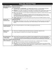
... using these items during cooktop usage ■■ This is OFF. Open and close the door, then start the cycle. ■■ Control - Make sure Demo mode (on some models, if a packaging spacer is separate from the microwave oven, or adjust the radio or TV antenna. ■■ Soil - Move the receiver away from the vent fan, automatically comes on motor rotation at 100% cooking power...
... using these items during cooktop usage ■■ This is OFF. Open and close the door, then start the cycle. ■■ Control - Make sure Demo mode (on some models, if a packaging spacer is separate from the microwave oven, or adjust the radio or TV antenna. ■■ Soil - Move the receiver away from the vent fan, automatically comes on motor rotation at 100% cooking power...
Owners Manual
Page 10
... user, operator or when this major appliance is intended for service or repair of this major appliance other rights that comes with this major appliance was purchased. Before contacting us to review the Troubleshooting or Problem Solver section of purchase, 1. the United States or Canada and 13. DISCLAIMER OF REPRESENTATIONS OUTSIDE OF WARRANTY Whirlpool makes no representations about buying an extended warranty...
... user, operator or when this major appliance is intended for service or repair of this major appliance other rights that comes with this major appliance was purchased. Before contacting us to review the Troubleshooting or Problem Solver section of purchase, 1. the United States or Canada and 13. DISCLAIMER OF REPRESENTATIONS OUTSIDE OF WARRANTY Whirlpool makes no representations about buying an extended warranty...


