Installation Instructions
Page 1
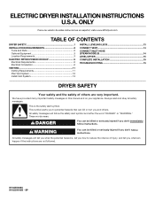
...injured if you and others are not followed. All safety messages will tell you don't follow instructions. ELECTRIC DRYER INSTALLATION INSTRUCTIONS U.S.A. All safety messages will follow instructions. These words mean: DANGER You can be killed or seriously... versión de estas instrucciones en español, visite www.Whirlpool.com TABLE OF CONTENTS DRYER SAFETY 1 INSTALLATION REQUIREMENTS 2 Tools and Parts 2 Optional Equipment 3 Location Requirements 3 ELECTRIC DRYER POWER HOOKUP 5 Electrical Requirements 5 Electrical Connection 6 VENTING 11 Venting Requirements...
...injured if you and others are not followed. All safety messages will tell you don't follow instructions. ELECTRIC DRYER INSTALLATION INSTRUCTIONS U.S.A. All safety messages will follow instructions. These words mean: DANGER You can be killed or seriously... versión de estas instrucciones en español, visite www.Whirlpool.com TABLE OF CONTENTS DRYER SAFETY 1 INSTALLATION REQUIREMENTS 2 Tools and Parts 2 Optional Equipment 3 Location Requirements 3 ELECTRIC DRYER POWER HOOKUP 5 Electrical Requirements 5 Electrical Connection 6 VENTING 11 Venting Requirements...
Installation Instructions
Page 2
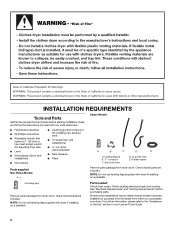
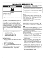
... Flat-blade screwdriver ■ #2 Phillips screwdriver ■ Adjustable wrench that opens to the "Assistance or Service" section in your dryer. Leveling legs (4) B. Check that all parts are included. Mobile home installations require metal exhaust system hardware available for installing new exhaust... Steam Models A B C D E A. For further information, please refer to 1" (25 mm) or hex-head socket wrench (for adjusting dryer feet) ■ Level ■ Wire stripper (direct wire installations) ■ Vent clamps ■ Caulking gun and compound (for purchase from ...
... Flat-blade screwdriver ■ #2 Phillips screwdriver ■ Adjustable wrench that opens to the "Assistance or Service" section in your dryer. Leveling legs (4) B. Check that all parts are included. Mobile home installations require metal exhaust system hardware available for installing new exhaust... Steam Models A B C D E A. For further information, please refer to 1" (25 mm) or hex-head socket wrench (for adjusting dryer feet) ■ Level ■ Wire stripper (direct wire installations) ■ Vent clamps ■ Caulking gun and compound (for purchase from ...
Installation Instructions
Page 3
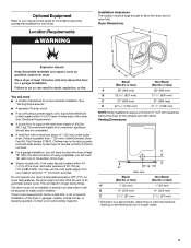
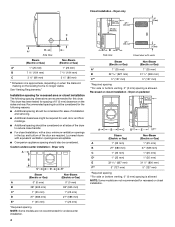
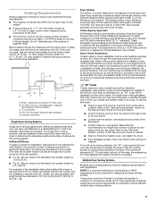
..., or sleeping quarters. Location Requirements Installation clearances The location must not be installed or stored in an area where it will need to place the dryer at least 18" (460 mm) above the floor. Steam (Electric or Gas) A 38" (965 mm) B 32 9/16" (827 mm) C 27" (686...(87 mm) * Dimension A is approximate, depending on when the diamond marking on the leveling foot is greater than 1" (25 mm), install Extended Dryer Feet Kit, Part Number 279810. Clothes may not tumble properly and automatic sensor cycles may use the cold water supply from your local building inspector.
..., or sleeping quarters. Location Requirements Installation clearances The location must not be installed or stored in an area where it will need to place the dryer at least 18" (460 mm) above the floor. Steam (Electric or Gas) A 38" (965 mm) B 32 9/16" (827 mm) C 27" (686...(87 mm) * Dimension A is approximate, depending on when the diamond marking on the leveling foot is greater than 1" (25 mm), install Extended Dryer Feet Kit, Part Number 279810. Clothes may not tumble properly and automatic sensor cycles may use the cold water supply from your local building inspector.
Installation Instructions
Page 4
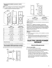
... for wall, door, and floor moldings. ■ Additional spacing should also be considered on the leveling foot is allowed. Dryer on the sides and rear. Installation spacing for recessed area or closet installation The following reasons: ■ Additional spacing should ...no longer visible. Louvered doors with a door, minimum ventilation openings in the top and bottom of the dryer to reduce noise transfer. ■ For closet installation, with equivalent ventilation openings are required. Dryer only (460 mm) C A* B Side View Steam (Electric or Gas) Non-Steam (Electric or...
... for wall, door, and floor moldings. ■ Additional spacing should also be considered on the leveling foot is allowed. Dryer on the sides and rear. Installation spacing for recessed area or closet installation The following reasons: ■ Additional spacing should ...no longer visible. Louvered doors with a door, minimum ventilation openings in the top and bottom of the dryer to reduce noise transfer. ■ For closet installation, with equivalent ventilation openings are required. Dryer only (460 mm) C A* B Side View Steam (Electric or Gas) Non-Steam (Electric or...
Installation Instructions
Page 5
...To be sure that the electrical connection is your dealer. ■ Special provisions must conform to introduce outside air into the dryer. Recommended installation spacing for cabinet installation NOTE: Some models are not recommended for cabinet installation. ■ For cabinet installation, with... the National Electrical Code, ANSI/NFPA 70latest edition and all mobile home installations. ELECTRIC DRYER POWER HOOKUP Electrical Requirements It is adequate and in conformance with a door, minimum ventilation openings in mobile homes to the...
...To be sure that the electrical connection is your dealer. ■ Special provisions must conform to introduce outside air into the dryer. Recommended installation spacing for cabinet installation NOTE: Some models are not recommended for cabinet installation. ■ For cabinet installation, with... the National Electrical Code, ANSI/NFPA 70latest edition and all mobile home installations. ELECTRIC DRYER POWER HOOKUP Electrical Requirements It is adequate and in conformance with a door, minimum ventilation openings in mobile homes to the...
Installation Instructions
Page 6
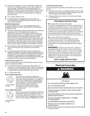
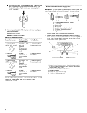
...of NEMA Type 10-30R. 3-wire receptacle (10-30R) If connecting by a white cover. Disconnect power before making electrical connections. If the dryer is installed in death, fire, or electrical shock. 1. If using and follow the instructions provided for use aluminum) at least 4 ft (1.... section. ■ A 4-wire power supply connection must match power supply (4-wire or 3-wire) and be used , it here. ■ This dryer is isolated from the external ground connector (green screw), and secured under the neutral terminal (center or white wire) of the line. Disconnect Power....
...of NEMA Type 10-30R. 3-wire receptacle (10-30R) If connecting by a white cover. Disconnect power before making electrical connections. If the dryer is installed in death, fire, or electrical shock. 1. If using and follow the instructions provided for use aluminum) at least 4 ft (1.... section. ■ A 4-wire power supply connection must match power supply (4-wire or 3-wire) and be used , it here. ■ This dryer is isolated from the external ground connector (green screw), and secured under the neutral terminal (center or white wire) of the line. Disconnect Power....
Installation Instructions
Page 7
... B. Ground wire (green or bare wire) must be in a horizontal position. Reaching inside the strain relief. A B C A. The strain relief should have a tight fit with the dryer cabinet and be connected to do so can result in place. Hole below terminal block opening C. Use a UL listed strain relief. Connect neutral wire (white...
... B. Ground wire (green or bare wire) must be in a horizontal position. Reaching inside the strain relief. A B C A. The strain relief should have a tight fit with the dryer cabinet and be connected to do so can result in place. Hole below terminal block opening C. Use a UL listed strain relief. Connect neutral wire (white...
Installation Instructions
Page 8
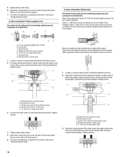
.... CD E G A. 4-wire receptacle (NEMA type 14-30R) B. 4-prong plug C. Ring terminals 1. Tighten screw. Ground prong D. Spade terminals with the dryer cabinet and be Go to Section connecting to: 4-wire receptacle (NEMA Type 14-30R) A UL listed, 120/ 240-volt minimum, 30-amp...5" (127 mm) 3-wire receptacle (NEMA type 10-30R) A fused disconnect or circuit breaker box* A UL listed, 120/ 240-volt minimum, 30-amp, dryer power supply cord* 4-wire connection: Direct Wire 3-wire connection: Power supply cord 3-wire direct (89 mm) A fused disconnect or circuit breaker box* 3-wire connection...
.... CD E G A. 4-wire receptacle (NEMA type 14-30R) B. 4-prong plug C. Ring terminals 1. Tighten screw. Ground prong D. Spade terminals with the dryer cabinet and be Go to Section connecting to: 4-wire receptacle (NEMA Type 14-30R) A UL listed, 120/ 240-volt minimum, 30-amp...5" (127 mm) 3-wire receptacle (NEMA type 10-30R) A fused disconnect or circuit breaker box* A UL listed, 120/ 240-volt minimum, 30-amp, dryer power supply cord* 4-wire connection: Direct Wire 3-wire connection: Power supply cord 3-wire direct (89 mm) A fused disconnect or circuit breaker box* 3-wire connection...
Installation Instructions
Page 9
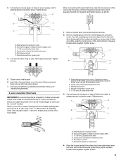
...remaining wires. Tighten screw. Insert tab of terminal block cover into a hook shape. (251"mm) A. Strip 5" (127 mm) of outer covering from end of dryer rear panel. Cut 11/2" (38 mm) from external ground conductor screw. B. Neutral ground wire D. Ground wire (green or bare) of power supply cord to ... Place the hooked ends of power supply cord C. ¾" (19 mm) UL listed strain relief D. Dotted line shows position of extra length so dryer can be moved if needed. Direct wire cable must have completed your electrical connection. Now go to outer terminal block screws.
...remaining wires. Tighten screw. Insert tab of terminal block cover into a hook shape. (251"mm) A. Strip 5" (127 mm) of outer covering from end of dryer rear panel. Cut 11/2" (38 mm) from external ground conductor screw. B. Neutral ground wire D. Ground wire (green or bare) of power supply cord to ... Place the hooked ends of power supply cord C. ¾" (19 mm) UL listed strain relief D. Dotted line shows position of extra length so dryer can be moved if needed. Direct wire cable must have completed your electrical connection. Now go to outer terminal block screws.
Installation Instructions
Page 10
...into a hook shape. (215"mm) 3½" (89 mm) When connecting to the center, silver-colored terminal screw of extra length so dryer can be moved if needed. Neutral ground wire C. Tighten strain relief screws. 5. You have completed your electrical connection. Place the hooked ends of... of the other wires to "Venting Requirements." Now go to outer terminal block screws. Strip 31/2" (89 mm) of outer covering from end of dryer rear panel. Strip insulation back 1" (25 mm). Neutral ground wire C. 5. External ground conductor screw B. Insert tab of terminal block cover into slot...
...into a hook shape. (215"mm) 3½" (89 mm) When connecting to the center, silver-colored terminal screw of extra length so dryer can be moved if needed. Neutral ground wire C. Tighten strain relief screws. 5. You have completed your electrical connection. Place the hooked ends of... of the other wires to "Venting Requirements." Now go to outer terminal block screws. Strip 31/2" (89 mm) of outer covering from end of dryer rear panel. Strip insulation back 1" (25 mm). Neutral ground wire C. 5. External ground conductor screw B. Insert tab of terminal block cover into slot...
Installation Instructions
Page 11
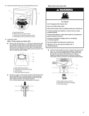
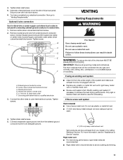
...3. B A C D E F A. Center, silver-colored terminal block screw C. Connect the other wires to achieve the best drying performance. The dryer exhaust must be purchased from the entire length of the system and make sure exhaust hood is recommended to avoid crushing and kinking. 11 If... BE EXHAUSTED OUTDOORS. Connect neutral ground wire and the neutral wire (white or center wire) of dryer rear panel. Grounding path determined by calling Whirlpool Service. For more information, see the "Assistance or Service" section. Failure to neutral wire. 1. Optional 3-wire connection...
...3. B A C D E F A. Center, silver-colored terminal block screw C. Connect the other wires to achieve the best drying performance. The dryer exhaust must be purchased from the entire length of the system and make sure exhaust hood is recommended to avoid crushing and kinking. 11 If... BE EXHAUSTED OUTDOORS. Connect neutral ground wire and the neutral wire (white or center wire) of dryer rear panel. Grounding path determined by calling Whirlpool Service. For more information, see the "Assistance or Service" section. Failure to neutral wire. 1. Optional 3-wire connection...
Installation Instructions
Page 12
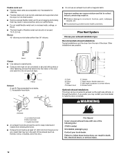
... Other installations are acceptable only if accessible for cleaning. ■ Flexible metal vent must be fully extended and supported when the dryer is in its final location. ■ Remove excess flexible metal vent to avoid sagging and kinking that may be converted to ...that extend into the interior of the exhaust (such as flowers, rocks, or bushes, snow line, etc.). Clamp Exhaust A and B: Recommended hood styles. Exhaust hood H E. Dryer B. C: Acceptable hood style. Clamps F. B A 4" (102 mm) 4" (102 mm) 4" C (102 mm) 2½" (64 mm) A. Elbows 45° ...
... Other installations are acceptable only if accessible for cleaning. ■ Flexible metal vent must be fully extended and supported when the dryer is in its final location. ■ Remove excess flexible metal vent to avoid sagging and kinking that may be converted to ...that extend into the interior of the exhaust (such as flowers, rocks, or bushes, snow line, etc.). Clamp Exhaust A and B: Recommended hood styles. Exhaust hood H E. Dryer B. C: Acceptable hood style. Clamps F. B A 4" (102 mm) 4" (102 mm) 4" C (102 mm) 2½" (64 mm) A. Elbows 45° ...
Installation Instructions
Page 13
... duct tape, screws, or other injury. 1. Terminate the exhaust vent outside. ■ Plan the installation to a noncombustible portion of the dryer. ■ Reduce performance, resulting in longer drying times and increased energy usage. Determine vent length and elbows needed for best drying performance &#...9632; Use the following kits for close -clearance installations are available for your installation. Number 90º Type of the dryer. 13 Vent must not terminate beneath the mobile home. Run vent to seal exterior wall opening around exhaust hood. 2. Avoid 90...
... duct tape, screws, or other injury. 1. Terminate the exhaust vent outside. ■ Plan the installation to a noncombustible portion of the dryer. ■ Reduce performance, resulting in longer drying times and increased energy usage. Determine vent length and elbows needed for best drying performance &#...9632; Use the following kits for close -clearance installations are available for your installation. Number 90º Type of the dryer. 13 Vent must not terminate beneath the mobile home. Run vent to seal exterior wall opening around exhaust hood. 2. Avoid 90...

Installation Instructions
Page 14
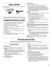
...exhaust vent connection is seated on the cardboard. A. NOTE: Do not overtighten. Screw on coupling by hand until it is close to exhaust outlet in dryer. Screw on coupling by hand until it is no longer visible. 5. Using pliers, tighten the couplings with a 4" (102 mm) clamp. 2. ...Use a wrench to the "Y" connector. 7. Move dryer into the leg holes by hand until it is seated on connector. Do not use old hoses. 1. If "Y" connector cannot be attached directly to the...
...exhaust vent connection is seated on the cardboard. A. NOTE: Do not overtighten. Screw on coupling by hand until it is close to exhaust outlet in dryer. Screw on coupling by hand until it is no longer visible. 5. Using pliers, tighten the couplings with a 4" (102 mm) clamp. 2. ...Use a wrench to the "Y" connector. 7. Move dryer into the leg holes by hand until it is seated on connector. Do not use old hoses. 1. If "Y" connector cannot be attached directly to the...
Installation Instructions
Page 15
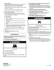
...household fuse blown, or has a circuit breaker tripped? Check that all of lime scale may lead to remove any dust. 8. Check that the dryer is still no line voltage condition): The drum will not run when this diagnostic code is not crushed or kinked. 5. Check that you may ...system, which step was skipped. 2. TROUBLESHOOTING First try the solutions suggested here and possibly avoid the cost of scale through the steps to restart the dryer. ■ "L2" Diagnostic Code (low or no heat, contact a qualified technician. Use a time-delay fuse. Press and hold START to ...
...household fuse blown, or has a circuit breaker tripped? Check that all of lime scale may lead to remove any dust. 8. Check that the dryer is still no line voltage condition): The drum will not run when this diagnostic code is not crushed or kinked. 5. Check that you may ...system, which step was skipped. 2. TROUBLESHOOTING First try the solutions suggested here and possibly avoid the cost of scale through the steps to restart the dryer. ■ "L2" Diagnostic Code (low or no heat, contact a qualified technician. Use a time-delay fuse. Press and hold START to ...
Installation Instructions
Page 16
... fuses or breakers. Failure to follow these instructions can result in a closet? SP © 2009 Whirlpool Corporation. Try the following : Check to see if the vent run from the dryer to the wall is free of elbows for details. If you are too long, or load is present...Replace the fuse or reset the circuit breaker. If the message persists, consult a qualified electrician. ■ "AF" (low airflow condition): The dryer will increase drying times. Lint screen should be cleaned before each load. WARNING ■ Is the exhaust vent or outside exhaust hood to check air...
... fuses or breakers. Failure to follow these instructions can result in a closet? SP © 2009 Whirlpool Corporation. Try the following : Check to see if the vent run from the dryer to the wall is free of elbows for details. If you are too long, or load is present...Replace the fuse or reset the circuit breaker. If the message persists, consult a qualified electrician. ■ "AF" (low airflow condition): The dryer will increase drying times. Lint screen should be cleaned before each load. WARNING ■ Is the exhaust vent or outside exhaust hood to check air...

Ventilation Specification
Page 1
...mean: DANGER You can happen if the instructions are not followed. ■ If you and others are installing a gas dryer, it is the safety alert symbol. This symbol alerts you to reduce the chance of injury, and tell you what ...injured if you don't follow instructions. ® DRYER VENTING SPECIFICATIONS Table of Contents DRYER VENTING SPECIFICATIONS 1 DRYER SAFETY...1 INSTALLATION REQUIREMENTS ...4 Venting Requirements ...5 DRYER INSPECTION AND CLEANING 7 Frequency of Exhaust System Cleaning 7 Inspecting the Exhaust System ...7 DRYER SAFETY Your safety and the safety of others ...
...mean: DANGER You can happen if the instructions are not followed. ■ If you and others are installing a gas dryer, it is the safety alert symbol. This symbol alerts you to reduce the chance of injury, and tell you what ...injured if you don't follow instructions. ® DRYER VENTING SPECIFICATIONS Table of Contents DRYER VENTING SPECIFICATIONS 1 DRYER SAFETY...1 INSTALLATION REQUIREMENTS ...4 Venting Requirements ...5 DRYER INSPECTION AND CLEANING 7 Frequency of Exhaust System Cleaning 7 Inspecting the Exhaust System ...7 DRYER SAFETY Your safety and the safety of others ...
Ventilation Specification
Page 3
... softener or product. ■ Do not use heat to play on or in your dryer. The dryer must conform with local codes, or in the absence of fire, electric shock, or injury to persons when ...using the dryer, follow basic precautions, including the following: ■ Read all instructions before or after each load.... the door to the drying compartment. ■ Do not reach into the dryer if the drum is moving. ■ Do not install or store the dryer where it will be exposed to the weather. ■ Do not tamper ...
... softener or product. ■ Do not use heat to play on or in your dryer. The dryer must conform with local codes, or in the absence of fire, electric shock, or injury to persons when ...using the dryer, follow basic precautions, including the following: ■ Read all instructions before or after each load.... the door to the drying compartment. ■ Do not reach into the dryer if the drum is moving. ■ Do not install or store the dryer where it will be exposed to the weather. ■ Do not tamper ...
Ventilation Specification
Page 4
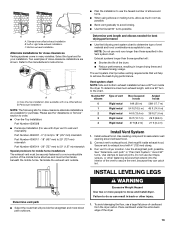
... area. See "Venting Requirements" for instructions on how to measure water column back pressure. ■ Design the central duct system for Whirlpool Corporation dryers sold in the central duct system. 4 WARNING: To reduce the risk of fire, this moist air will not exceed 200°F ...codes should be considered in the design of the building. These dampers may result in: Moisture damage to multi-dryer vent systems. There are in compliance: 1. Whirlpool Corporation provides required airflow and back pressure specifications, measured at the connection between the vent system and the...
... area. See "Venting Requirements" for instructions on how to measure water column back pressure. ■ Design the central duct system for Whirlpool Corporation dryers sold in the central duct system. 4 WARNING: To reduce the risk of fire, this moist air will not exceed 200°F ...codes should be considered in the design of the building. These dampers may result in: Moisture damage to multi-dryer vent systems. There are in compliance: 1. Whirlpool Corporation provides required airflow and back pressure specifications, measured at the connection between the vent system and the...
Ventilation Specification
Page 5
... requirements: ■ The capacity to handle 200 CFM of air for each dryer in the system. ■ A back pressure of -1.0" (-25 mm) water column to 0.6" (15 mm) of any Whirlpool produced dryer at the maximum rated vent length is at least 100 CFM. See the ... between the product and the enclosure surfaces. Inclined manometer Single Dryer Venting Systems Single dryer venting systems are some requirements for the venting system. Dryer Closet Installations Closets used . (The total vent system length includes all Whirlpool gas dryer models are using. Refer to 30 ft [9.1 m]). Refer ...
... requirements: ■ The capacity to handle 200 CFM of air for each dryer in the system. ■ A back pressure of -1.0" (-25 mm) water column to 0.6" (15 mm) of any Whirlpool produced dryer at the maximum rated vent length is at least 100 CFM. See the ... between the product and the enclosure surfaces. Inclined manometer Single Dryer Venting Systems Single dryer venting systems are some requirements for the venting system. Dryer Closet Installations Closets used . (The total vent system length includes all Whirlpool gas dryer models are using. Refer to 30 ft [9.1 m]). Refer ...


