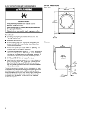
Dimension Guide
Page 1
... (102 mm) 4" (102 mm) 2½" (64 mm) A. To determine maximum exhaust length, add one 90° turn inside the dryer. Plan the installation to change without notice. Box hood C. Angled hood (acceptable) The Vent system chart provides venting requirements that will provide the ... (8.2 m) 21 ft. (6.4 m) Do not use vent runs longer than specified in .2 (155 cm2) 1" (25 mm) 1" (25 mm) Because Whirlpool Corporation policy includes a continuous commitment to improve our products, we reserve the right to use plastic or metal foil vet. Dimensions are for the exhaust...
... (102 mm) 4" (102 mm) 2½" (64 mm) A. To determine maximum exhaust length, add one 90° turn inside the dryer. Plan the installation to change without notice. Box hood C. Angled hood (acceptable) The Vent system chart provides venting requirements that will provide the ... (8.2 m) 21 ft. (6.4 m) Do not use vent runs longer than specified in .2 (155 cm2) 1" (25 mm) 1" (25 mm) Because Whirlpool Corporation policy includes a continuous commitment to improve our products, we reserve the right to use plastic or metal foil vet. Dimensions are for the exhaust...
Installation Instructions
Page 2
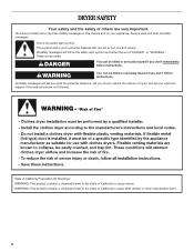
... reduce the chance of others . All safety messages will follow instructions. We have provided many important safety messages in this manual and on your appliance. DRYER SAFETY Your safety and the safety of injury, and tell you what can happen if the instructions are very important.
... reduce the chance of others . All safety messages will follow instructions. We have provided many important safety messages in this manual and on your appliance. DRYER SAFETY Your safety and the safety of injury, and tell you what can happen if the instructions are very important.
Installation Instructions
Page 3
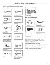
... pedestal, do not permit, installing dryer in dryer drum. Check existing electrical supply and venting. Contact your dryer. Tools needed : (Not supplied with dryer) Refer to 1" (25 mm) or hex-head socket wrench Utility knife Tape measure Pliers Long ..., mobile homes, or sleeping quarters. Level Caulking gun and compound (for your local building inspector. Optional Equipment: (Not supplied with dryer) Check local codes. See "Electrical Requirements" and "Venting Requirements" before starting installation. INSTALLATION REQUIREMENTS TOOLS AND PARTS Gather the required ...
... pedestal, do not permit, installing dryer in dryer drum. Check existing electrical supply and venting. Contact your dryer. Tools needed : (Not supplied with dryer) Refer to 1" (25 mm) or hex-head socket wrench Utility knife Tape measure Pliers Long ..., mobile homes, or sleeping quarters. Level Caulking gun and compound (for your local building inspector. Optional Equipment: (Not supplied with dryer) Check local codes. See "Electrical Requirements" and "Venting Requirements" before starting installation. INSTALLATION REQUIREMENTS TOOLS AND PARTS Gather the required ...
Installation Instructions
Page 4
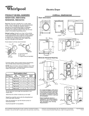
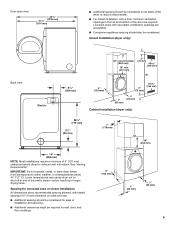
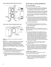
... within 2 ft. (610 mm) of either side of installation and servicing; Add spacing on all sides of 1" (25 mm) under entire dryer. You may not operate correctly. For each arrangement, consider allowing more space for best performance. ■■ Level floor with maximum slope of....7 kg). If slope is installed, top and bottom air openings in door are provided. ■■ 20-100 psi (138-690 kPa) for ease of dryer. spacing for companion appliances and clearances for proper exhaust installation. Side view: 1" (25 mm) 29" (736 mm) Left or right side exhaust 6 7/8"...
... within 2 ft. (610 mm) of either side of installation and servicing; Add spacing on all sides of 1" (25 mm) under entire dryer. You may not operate correctly. For each arrangement, consider allowing more space for best performance. ■■ Level floor with maximum slope of....7 kg). If slope is installed, top and bottom air openings in door are provided. ■■ 20-100 psi (138-690 kPa) for ease of dryer. spacing for companion appliances and clearances for proper exhaust installation. Side view: 1" (25 mm) 29" (736 mm) Left or right side exhaust 6 7/8"...
Installation Instructions
Page 5
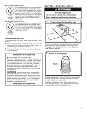
... be required for wall, door, and floor moldings. 4" (102 mm) 1" (25 mm) 1" (25 mm) 5 IMPORTANT: Do not operate, install, or store dryer where it will be considered. Door open view: 481/8" (1238 mm) 471/8" (1197 mm) ■■ Additional spacing should be considered on all sides of... the dryer to reduce noise transfer. ■■ For closet installation, with tested spacing of 0" (0 mm) clearance on sides and rear. ■■ Additional ...
... be required for wall, door, and floor moldings. 4" (102 mm) 1" (25 mm) 1" (25 mm) 5 IMPORTANT: Do not operate, install, or store dryer where it will be considered. Door open view: 481/8" (1238 mm) 471/8" (1197 mm) ■■ Additional spacing should be considered on all sides of... the dryer to reduce noise transfer. ■■ For closet installation, with tested spacing of 0" (0 mm) clearance on sides and rear. ■■ Additional ...
Installation Instructions
Page 6
... properly install your "Use and Care Guide". ■■ Special provisions must conform to the neutral conductor (white wire) within the dryer. The kit should be removed from your responsibility: ■■ To contact a qualified electrical installer. ■■ To be used...the neutral conductors. The wires that the ground path is recommended that a qualified electrician determine that connect to introduce outside air into dryer. Mobile home - For further information, see "Optional 3-wire connection" section. ■■ A 4-wire power supply connection must ...
... properly install your "Use and Care Guide". ■■ Special provisions must conform to the neutral conductor (white wire) within the dryer. The kit should be removed from your responsibility: ■■ To contact a qualified electrical installer. ■■ To be used...the neutral conductors. The wires that the ground path is recommended that a qualified electrician determine that connect to introduce outside air into dryer. Mobile home - For further information, see "Optional 3-wire connection" section. ■■ A 4-wire power supply connection must ...
Installation Instructions
Page 7
... nonmetallic sheathed copper cable (with ground wire), covered with flexible metallic conduit. GROUNDING INSTRUCTIONS � For a grounded, cord-connected dryer: This dryer must have 4 10-gauge solid copper wires and match a 4-wire receptacle of malfunction or breakdown, grounding will not fit the ... m) long. All current-carrying wires must be identified by hand, use a wrench to connect the exhaust vent. 7 WARNING: Improper connection of dryer. SAVE THESE INSTRUCTIONS To avoid damaging floor, use aluminum) at least 4 ft. (1.22 m) long, must match power supply (4-wire or 3-...
... nonmetallic sheathed copper cable (with ground wire), covered with flexible metallic conduit. GROUNDING INSTRUCTIONS � For a grounded, cord-connected dryer: This dryer must have 4 10-gauge solid copper wires and match a 4-wire receptacle of malfunction or breakdown, grounding will not fit the ... m) long. All current-carrying wires must be identified by hand, use a wrench to connect the exhaust vent. 7 WARNING: Improper connection of dryer. SAVE THESE INSTRUCTIONS To avoid damaging floor, use aluminum) at least 4 ft. (1.22 m) long, must match power supply (4-wire or 3-...
Installation Instructions
Page 9
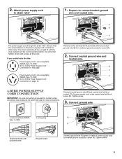
... (NEMA Type 10-30R): Go to external ground conductor screw (A). Connect ground wire 4-wire receptacle (NEMA type 14-30R) 4-prong plug Spade terminals with the dryer cabinet and be in a horizontal position. Do not further tighten strain relief screws at this page. If your outlet looks like this: Power supply cord...
... (NEMA Type 10-30R): Go to external ground conductor screw (A). Connect ground wire 4-wire receptacle (NEMA type 14-30R) 4-prong plug Spade terminals with the dryer cabinet and be in a horizontal position. Do not further tighten strain relief screws at this page. If your outlet looks like this: Power supply cord...
Installation Instructions
Page 10
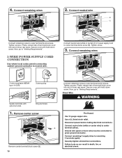
...plug Spade terminals with hold -down screw. Direct Wire B Remove center terminal block screw (B). 10 Finally, reinsert tab of terminal block cover into slot of dryer rear panel. Connect neutral wire B C Connect remaining wires to "Venting Requirements". Tighten screw. 3. Now, go to "Venting Requirements". 3-wire Power Supply Cord... of power supply cord to neutral wire. Secure cover with upturned ends Ring terminals 1. Connect neutral wire (white or center) (C) of dryer rear panel. Remove center screw Connect remaining wires to outer terminal block screws. 4.
...plug Spade terminals with hold -down screw. Direct Wire B Remove center terminal block screw (B). 10 Finally, reinsert tab of terminal block cover into slot of dryer rear panel. Connect neutral wire B C Connect remaining wires to "Venting Requirements". Tighten screw. 3. Now, go to "Venting Requirements". 3-wire Power Supply Cord... of power supply cord to neutral wire. Secure cover with upturned ends Ring terminals 1. Connect neutral wire (white or center) (C) of dryer rear panel. Remove center screw Connect remaining wires to outer terminal block screws. 4.
Installation Instructions
Page 11
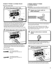
...Direct Connection on page 12. Tighten strain relief screw against the direct wire cable. Remove neutral ground wire (E) from end of extra length so dryer may be in a horizontal position. Attach direct wire cable to connect neutral ground wire and neutral wire E B A Remove center terminal block ... IMPORTANT: A 4-wire connection is required for direct connection (251"mm) (127 5" mm) Direct wire cable must have a tight fit with the dryer cabinet and be moved if needed. Strip 5" (127 mm) of wire under terminal block screw, facing to 3-Wire Direct Connection on this page....
...Direct Connection on page 12. Tighten strain relief screw against the direct wire cable. Remove neutral ground wire (E) from end of extra length so dryer may be in a horizontal position. Attach direct wire cable to connect neutral ground wire and neutral wire E B A Remove center terminal block ... IMPORTANT: A 4-wire connection is required for direct connection (251"mm) (127 5" mm) Direct wire cable must have a tight fit with the dryer cabinet and be moved if needed. Strip 5" (127 mm) of wire under terminal block screw, facing to 3-Wire Direct Connection on this page....

Installation Instructions
Page 12
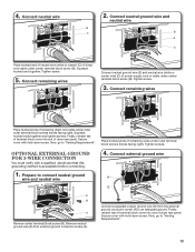
Shape wire ends into slot of dryer rear panel. If using 3-wire cable with ground wire, cut bare wire even with hold-down screw. Finally, reinsert tab of terminal block cover into ... local codes permit connecting cabinet-ground conductor to external ground conductor screw (A). Strip 31/2" (89 mm) of outer covering from end of extra length so dryer may be moved if needed. Remove center screw B Place hooked ends of remaining direct wire cable wires under center screw of direct wire cable to...
Shape wire ends into slot of dryer rear panel. If using 3-wire cable with ground wire, cut bare wire even with hold-down screw. Finally, reinsert tab of terminal block cover into ... local codes permit connecting cabinet-ground conductor to external ground conductor screw (A). Strip 31/2" (89 mm) of outer covering from end of extra length so dryer may be moved if needed. Remove center screw B Place hooked ends of remaining direct wire cable wires under center screw of direct wire cable to...
Installation Instructions
Page 13
4. Squeeze hooked ends together and tighten screws. Place hooked ends of dryer rear panel. Tighten screws. Connect external ground wire A G E B A Remove center terminal block screw (B). Finally, reinsert tab of terminal block cover into slot of ...outer terminal block screws (hooks facing right). Tighten screw. 5. Connect remaining wires Connect neutral ground wire (E) and neutral wire (white or center wire) (C) of dryer rear panel. Finally, reinsert tab of terminal block cover into slot of remaining wires under center terminal block screw (B). Now, go to an adequate ground...
4. Squeeze hooked ends together and tighten screws. Place hooked ends of dryer rear panel. Tighten screws. Connect external ground wire A G E B A Remove center terminal block screw (B). Finally, reinsert tab of terminal block cover into slot of ...outer terminal block screws (hooks facing right). Tighten screw. 5. Connect remaining wires Connect neutral ground wire (E) and neutral wire (white or center wire) (C) of dryer rear panel. Finally, reinsert tab of terminal block cover into slot of remaining wires under center terminal block screw (B). Now, go to an adequate ground...

Installation Instructions
Page 14
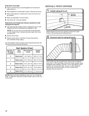
... exceed 7 3/4 ft. (2.4 m). Flexible metal vent: (Acceptable only if accessible to clean) ■■ Must be fully extended and supported in final dryer location. ■■ Remove excess to avoid crushing and kinking. NOTE: If using an existing vent system, clean lint from ground or any gas vent..., chimney, wall, ceiling, attic, crawlspace, or a concealed space of a building. Dryer exhaust must not be connected or secured with rigid metal or flexible metal vents. Do not use plastic or metal foil vent. Rigid metal vent...
... exceed 7 3/4 ft. (2.4 m). Flexible metal vent: (Acceptable only if accessible to clean) ■■ Must be fully extended and supported in final dryer location. ■■ Remove excess to avoid crushing and kinking. NOTE: If using an existing vent system, clean lint from ground or any gas vent..., chimney, wall, ceiling, attic, crawlspace, or a concealed space of a building. Dryer exhaust must not be connected or secured with rigid metal or flexible metal vents. Do not use plastic or metal foil vent. Rigid metal vent...
Installation Instructions
Page 15
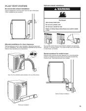
... mobile homes: Exhaust vent must contact your installation. Alternate installations for your local dealer to have dryer converted. You must be converted to a noncombustible portion of the dryer. Two close clearances Venting systems come in death or fire. Optional exhaust installations: WARNING Fire Hazard... use a metal foil vent. Terminate exhaust vent outside. Do not use a plastic vent. If you prefer, dryer may be securely fastened to exhaust out right side, left side, or through bottom. Refer to follow these instructions can result in ...
... mobile homes: Exhaust vent must contact your installation. Alternate installations for your local dealer to have dryer converted. You must be converted to a noncombustible portion of the dryer. Two close clearances Venting systems come in death or fire. Optional exhaust installations: WARNING Fire Hazard... use a metal foil vent. Terminate exhaust vent outside. Do not use a plastic vent. If you prefer, dryer may be securely fastened to exhaust out right side, left side, or through bottom. Refer to follow these instructions can result in ...
Installation Instructions
Page 16
...System Chart provides venting requirements that will provide straightest and most direct path outdoors. ■■ Plan installation to use fewest number of dryer. ■■ Reduce performance, resulting in Vent System Chart. Use clamps to use vent runs longer than those specified in longer drying... times and increased energy usage. To determine maximum exhaust length, add one 90º turn inside the dryer. Connect vent to exhaust hood with 4" (102 mm) clamp. NOTE: Do not use . Avoid 90° turns. Secure vent to...
...System Chart provides venting requirements that will provide straightest and most direct path outdoors. ■■ Plan installation to use fewest number of dryer. ■■ Reduce performance, resulting in Vent System Chart. Use clamps to use vent runs longer than those specified in longer drying... times and increased energy usage. To determine maximum exhaust length, add one 90º turn inside the dryer. Connect vent to exhaust hood with 4" (102 mm) clamp. NOTE: Do not use . Avoid 90° turns. Secure vent to...
Installation Instructions
Page 17
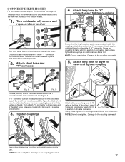
The dryer must be connected to the cold water faucet using the new inlet hoses. Attach short hose and "Y" connector...not overtighten. Remove old rubber washer from inlet hose and replace with additional two-thirds turn. Attach this end to dryer fill valve and tighten coupling Fig. Attach washer cold inlet hose to other end of long hose to fill valve at bottom... of dryer back panel. Attach long hose to the "Y" connector. B If space permits, attach the brass female end of the long...
The dryer must be connected to the cold water faucet using the new inlet hoses. Attach short hose and "Y" connector...not overtighten. Remove old rubber washer from inlet hose and replace with additional two-thirds turn. Attach this end to dryer fill valve and tighten coupling Fig. Attach washer cold inlet hose to other end of long hose to fill valve at bottom... of dryer back panel. Attach long hose to the "Y" connector. B If space permits, attach the brass female end of the long...
Installation Instructions
Page 18
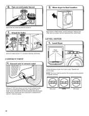
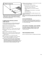
... Not Level LEVEL Not Level 18 Check for leaks around "Y" connector, faucets, and hoses. Level dryer 1. Connect Vent 1. Connect vent to exhaust outlet Place level here Check levelness of dryer from front to side. Repeat from side to back. Using a 4" (102 mm) clamp, connect... vent to exhaust hood with a 4" (102 mm) clamp. 6. Turn on . 7. Level Dryer Check for leaks Move dryer to final location Check that vent is clean. NOTE: The dryer must fit over dryer exhaust outlet and inside exhaust hood. If connecting to existing vent, make sure vent is secured to...
... Not Level LEVEL Not Level 18 Check for leaks around "Y" connector, faucets, and hoses. Level dryer 1. Connect Vent 1. Connect vent to exhaust outlet Place level here Check levelness of dryer from front to side. Repeat from side to back. Using a 4" (102 mm) clamp, connect... vent to exhaust hood with a 4" (102 mm) clamp. 6. Turn on . 7. Level Dryer Check for leaks Move dryer to final location Check that vent is clean. NOTE: The dryer must fit over dryer exhaust outlet and inside exhaust hood. If connecting to existing vent, make sure vent is secured to...
Installation Instructions
Page 19
...into an outlet and/or electrical supply. • Household fuse is intact and tight, or circuit breaker has not tripped. • Dryer door is available to the need for levelness. Door Reversal If you have all packaging materials. For further information, see "Assistance or ...Service" section in a running or "On" position. • Start button has been pushed firmly. • Dryer is plugged into a grounded outlet. This odor is common when heating element is first heated. Do not select Air Only Temperature setting. NOTE: ...
...into an outlet and/or electrical supply. • Household fuse is intact and tight, or circuit breaker has not tripped. • Dryer door is available to the need for levelness. Door Reversal If you have all packaging materials. For further information, see "Assistance or ...Service" section in a running or "On" position. • Start button has been pushed firmly. • Dryer is plugged into a grounded outlet. This odor is common when heating element is first heated. Do not select Air Only Temperature setting. NOTE: ...
Owners Manual
Page 2
... or seriously injured if you don't follow instructions. All safety messages will tell you what can kill or hurt you and others are not followed. 2 DRYER SAFETY Your safety and the safety of injury, and tell you what the potential hazard is the safety alert symbol.
... or seriously injured if you don't follow instructions. All safety messages will tell you what can kill or hurt you and others are not followed. 2 DRYER SAFETY Your safety and the safety of injury, and tell you what the potential hazard is the safety alert symbol.

Owners Manual
Page 3
... electrically grounded in accordance with local codes, or in the absence of local codes, with the National Fuel Gas Code, ANSI Z223.1/NFPA 54. The dryer must be followed to minimize the risk of fire or explosion, or to do not use a gas detector approved by smell. Follow the gas supplier...
... electrically grounded in accordance with local codes, or in the absence of local codes, with the National Fuel Gas Code, ANSI Z223.1/NFPA 54. The dryer must be followed to minimize the risk of fire or explosion, or to do not use a gas detector approved by smell. Follow the gas supplier...


