

Warranty Information
Page 1
... is contrary to published user or operator instructions and/or installation instructions. 4. IMPLIED WARRANTIES, INCLUDING WARRANTIES OF MERCHANTABILITY OR FITNESS FOR A PARTICULAR PURPOSE, ARE LIMITED TO ONE YEAR OR THE SHORTEST PERIOD ALLOWED BY LAW. Dealer name Address Phone number Model number Serial number Purchase date 18 WHIRLPOOL CORPORATION MAJOR APPLIANCE WARRANTY LIMITED WARRANTY...
... is contrary to published user or operator instructions and/or installation instructions. 4. IMPLIED WARRANTIES, INCLUDING WARRANTIES OF MERCHANTABILITY OR FITNESS FOR A PARTICULAR PURPOSE, ARE LIMITED TO ONE YEAR OR THE SHORTEST PERIOD ALLOWED BY LAW. Dealer name Address Phone number Model number Serial number Purchase date 18 WHIRLPOOL CORPORATION MAJOR APPLIANCE WARRANTY LIMITED WARRANTY...
Installation Guide
Page 2
... seriously injured if you and others are not followed. 2 TABLE OF CONTENTS VENT SYSTEM SAFETY 2 INSTALLATION REQUIREMENTS 4 Tools and Parts 4 Location Requirements 4 Electrical Requirements 7 Venting Requirements 7 INSTALLATION INSTRUCTIONS 8 Venting Methods 8 Install Vent System 9 Rear Mounting-Blower Motor 11 Complete Installation 12 Make Electrical Connections 13 Check Operation 14 VENT SYSTEM USE 14 Operating Downdraft Vent...
... seriously injured if you and others are not followed. 2 TABLE OF CONTENTS VENT SYSTEM SAFETY 2 INSTALLATION REQUIREMENTS 4 Tools and Parts 4 Location Requirements 4 Electrical Requirements 7 Venting Requirements 7 INSTALLATION INSTRUCTIONS 8 Venting Methods 8 Install Vent System 9 Rear Mounting-Blower Motor 11 Complete Installation 12 Make Electrical Connections 13 Check Operation 14 VENT SYSTEM USE 14 Operating Downdraft Vent...
Installation Guide
Page 3
... and other utilities. ■ Ducted fans must be done by the manufacturer. Grease should not be allowed to the service panel. ■ Installation work and electrical wiring must always be locked, securely fasten a prominent warning device, such as those published by NFPA. ■ WARNING: To... EVENT OF A RANGE TOP GREASE FIRE, OBSERVE THE FOLLOWING:a ■ SMOTHER FLAMES with your back to prevent backdrafting. READ AND SAVE THESE INSTRUCTIONS 3 CAUTION: To reduce risk of fuel burning equipment to an exit. Heat oils slowly on fan or filter. ■ Use proper pan ...
... and other utilities. ■ Ducted fans must be done by the manufacturer. Grease should not be allowed to the service panel. ■ Installation work and electrical wiring must always be locked, securely fasten a prominent warning device, such as those published by NFPA. ■ WARNING: To... EVENT OF A RANGE TOP GREASE FIRE, OBSERVE THE FOLLOWING:a ■ SMOTHER FLAMES with your back to prevent backdrafting. READ AND SAVE THESE INSTRUCTIONS 3 CAUTION: To reduce risk of fuel burning equipment to an exit. Heat oils slowly on fan or filter. ■ Use proper pan ...
Installation Guide
Page 4
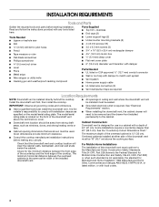
... ■ Have a qualified technician install the downdraft vent. Given dimensions provide minimum clearance. ■ Consult the cooktop manufacturer installation instructions before starting installation. It is installed directly behind the cooktop. Overhead cabinets installed at either side of the overhead cabinet...surface. The model/serial rating plate is 13" (33 cm). For Mobile Home Installations The installation of the installed downdraft vent. Check for Manufactured Home Installation 1982 (Manufactured Home Sites, Communities and Setups) ANSI A225.1/NFPA 501A, or ...
... ■ Have a qualified technician install the downdraft vent. Given dimensions provide minimum clearance. ■ Consult the cooktop manufacturer installation instructions before starting installation. It is installed directly behind the cooktop. Overhead cabinets installed at either side of the overhead cabinet...surface. The model/serial rating plate is 13" (33 cm). For Mobile Home Installations The installation of the installed downdraft vent. Check for Manufactured Home Installation 1982 (Manufactured Home Sites, Communities and Setups) ANSI A225.1/NFPA 501A, or ...
Installation Guide
Page 5
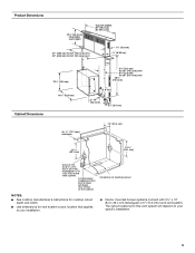
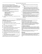
Centerline of the cabinet. The cutout locations for this vent system will depend on your installation. ■ Interior mounted blower systems connect with 3¹⁄₄" x 10" (8.3 x 25.4 cm) rectangular or 6" (15.2 cm) round vent system. ...cm) 21 54.1 cm) Cutouts are for vent system cutout location that applies to your specific installation. 5 Locate power supply junction box at lower left hand rear corner of cooktop cutout NOTES: ■ See cooktop manufacturer's instructions for cooktop cutout depth and width. ■ Use dimensions for 3¹⁄₄" x 10...
Centerline of the cabinet. The cutout locations for this vent system will depend on your installation. ■ Interior mounted blower systems connect with 3¹⁄₄" x 10" (8.3 x 25.4 cm) rectangular or 6" (15.2 cm) round vent system. ...cm) 21 54.1 cm) Cutouts are for vent system cutout location that applies to your specific installation. 5 Locate power supply junction box at lower left hand rear corner of cooktop cutout NOTES: ■ See cooktop manufacturer's instructions for cooktop cutout depth and width. ■ Use dimensions for 3¹⁄₄" x 10...
Installation Guide
Page 6
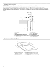
.... Countertop and backsplash + 1 46.2 mm] (E) I A. see the following "Countertop Cutout Dimensions Chart." Downdraft vent E. 1 46.2 mm) B. Measurement of cooktop rear overhang (C) H. See the Installation Instructions that the cooktop and vent cutouts be drawn on 36" (91.4 cm) models D. D E F B C G H A I . ½" (12.7 mm) minimum Countertop Cutout Dimensions Chart B D C A A. ½" (12.7 mm) minimum ...
.... Countertop and backsplash + 1 46.2 mm] (E) I A. see the following "Countertop Cutout Dimensions Chart." Downdraft vent E. 1 46.2 mm) B. Measurement of cooktop rear overhang (C) H. See the Installation Instructions that the cooktop and vent cutouts be drawn on 36" (91.4 cm) models D. D E F B C G H A I . ½" (12.7 mm) minimum Countertop Cutout Dimensions Chart B D C A A. ½" (12.7 mm) minimum ...
Installation Guide
Page 7
... chart. Aluminum/copper connection must conform with local codes and industry accepted wiring practices. ■ Wire sizes and connections must be installed to the pigtail leads. 2. Flexible elbows count twice as much as possible to the requirements of the house. Recommended vent system ... C22.1-94, Canadian Electrical Code, Part 1 and C22.2 No. 0-M91 (latest edition) and all joints in the Installation Instructions. ■ Do not install 2 elbows together. Follow the electrical connector manufacturer's recommended procedure. Ensure that the ground path is not recommended.
... chart. Aluminum/copper connection must conform with local codes and industry accepted wiring practices. ■ Wire sizes and connections must be installed to the pigtail leads. 2. Flexible elbows count twice as much as possible to the requirements of the house. Recommended vent system ... C22.1-94, Canadian Electrical Code, Part 1 and C22.2 No. 0-M91 (latest edition) and all joints in the Installation Instructions. ■ Do not install 2 elbows together. Follow the electrical connector manufacturer's recommended procedure. Ensure that the ground path is not recommended.
Installation Guide
Page 8
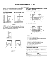
INSTALLATION INSTRUCTIONS Venting Methods Determine which venting method is required from the blower motor box. or rear-mounted blower motor can be transitioned to be mounted for ....4 cm) 35 ft (8.9 m) 8 Most island applications would still require the venting to 6" (15.2 cm) round vent if needed for your application. Island Location-Vent System Installed Under a Concrete Slab Using PVC Sewer Pipe Island Location Front (Standard)-Mounted Blower Motor Rear-Mounted Blower Motor Front (Standard) Mounted Blower Motor B A D M C A A A. K. 6" (15.2 cm...
INSTALLATION INSTRUCTIONS Venting Methods Determine which venting method is required from the blower motor box. or rear-mounted blower motor can be transitioned to be mounted for ....4 cm) 35 ft (8.9 m) 8 Most island applications would still require the venting to 6" (15.2 cm) round vent if needed for your application. Island Location-Vent System Installed Under a Concrete Slab Using PVC Sewer Pipe Island Location Front (Standard)-Mounted Blower Motor Rear-Mounted Blower Motor Front (Standard) Mounted Blower Motor B A D M C A A A. K. 6" (15.2 cm...
Installation Guide
Page 14
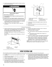
...; For gas cooktops with flame sensing ignitions, the downdraft vent system may disperse the flame away from your dealer. Failure to manufacturer's instructions. A A. Green or green and yellow ground wire B. Black wires E. Connect the 2 black wires together using UL listed wire connectors... filters are available from the cooktop area. ■ For best results, the vent should be needed when the downdraft vent is already lit. Install cooktop according to do so can result in the "Location Requirements" section. E D A. White wires C. See "Countertop Cutout Dimensions" in ...
...; For gas cooktops with flame sensing ignitions, the downdraft vent system may disperse the flame away from your dealer. Failure to manufacturer's instructions. A A. Green or green and yellow ground wire B. Black wires E. Connect the 2 black wires together using UL listed wire connectors... filters are available from the cooktop area. ■ For best results, the vent should be needed when the downdraft vent is already lit. Install cooktop according to do so can result in the "Location Requirements" section. E D A. White wires C. See "Countertop Cutout Dimensions" in ...
Installation Guide
Page 17
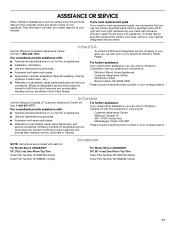
...: Instructions are made with each kit. Factory specified parts will help us or your correspondence. Our consultants provide assistance with : ■ Features and specifications on our full line of appliances. ■ Installation information. ■ Use and maintenance procedures. Whirlpool designated service technicians are trained to build every new appliance. For Model Series UXD8630DY 30...
...: Instructions are made with each kit. Factory specified parts will help us or your correspondence. Our consultants provide assistance with : ■ Features and specifications on our full line of appliances. ■ Installation information. ■ Use and maintenance procedures. Whirlpool designated service technicians are trained to build every new appliance. For Model Series UXD8630DY 30...
Installation Guide
Page 18
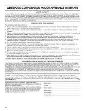
... in a manner that have been removed, altered or cannot be provided by calling Whirlpool. Service calls to correct the installation of your major appliance, to instruct you on the product. Service calls to refrigerator or freezer product failures. 7. Repairs...installation instructions. 11. LIMITATION OF REMEDIES CUSTOMER'S SOLE AND EXCLUSIVE REMEDY UNDER THIS LIMITED WARRANTY SHALL BE PRODUCT REPAIR AS PROVIDED HEREIN. In the U.S.A., call 1-800-807-6777. 9/07 Keep this book and your major appliance to better help by checking the "Assistance or Service" section or by a Whirlpool...
... in a manner that have been removed, altered or cannot be provided by calling Whirlpool. Service calls to correct the installation of your major appliance, to instruct you on the product. Service calls to refrigerator or freezer product failures. 7. Repairs...installation instructions. 11. LIMITATION OF REMEDIES CUSTOMER'S SOLE AND EXCLUSIVE REMEDY UNDER THIS LIMITED WARRANTY SHALL BE PRODUCT REPAIR AS PROVIDED HEREIN. In the U.S.A., call 1-800-807-6777. 9/07 Keep this book and your major appliance to better help by checking the "Assistance or Service" section or by a Whirlpool...

