Installation Guide
Page 2
... System 9 Rear Mounting-Blower Motor 11 Complete Installation 12 Make Electrical Connections 13 Check Operation 14 VENT SYSTEM USE 14 Operating Downdraft Vent 15 VENT SYSTEM CARE 15 Surface of Downdraft Vent 15 Filters 15 WIRING DIAGRAM 16 ASSISTANCE OR SERVICE 17 In the U.S.A 17 In Canada 17 Accessories 17 WARRANTY 18...
... System 9 Rear Mounting-Blower Motor 11 Complete Installation 12 Make Electrical Connections 13 Check Operation 14 VENT SYSTEM USE 14 Operating Downdraft Vent 15 VENT SYSTEM CARE 15 Surface of Downdraft Vent 15 Filters 15 WIRING DIAGRAM 16 ASSISTANCE OR SERVICE 17 In the U.S.A 17 In Canada 17 Accessories 17 WARRANTY 18...
Installation Guide
Page 4
... (Manufactured Home Sites, Communities and Setups) ANSI A225.1/NFPA 501A, or latest edition, or with installation clearances specified on the front of the installed downdraft vent. Check for pilot holes ■ Pencil ■ Tape measure or ruler ■ 3.5 x 9.5 mm screws (3) ■ 3¹⁄... clamps/duct tape as windows, doors, and strong heating vents or fans. ■ Cabinet opening dimensions that the downdraft vent and cooktop location will need to be sealed. See the "Countertop Cutout Dimensions Chart." See "Electrical Requirements" section. ■...
... (Manufactured Home Sites, Communities and Setups) ANSI A225.1/NFPA 501A, or latest edition, or with installation clearances specified on the front of the installed downdraft vent. Check for pilot holes ■ Pencil ■ Tape measure or ruler ■ 3.5 x 9.5 mm screws (3) ■ 3¹⁄... clamps/duct tape as windows, doors, and strong heating vents or fans. ■ Cabinet opening dimensions that the downdraft vent and cooktop location will need to be sealed. See the "Countertop Cutout Dimensions Chart." See "Electrical Requirements" section. ■...
Installation Guide
Page 6
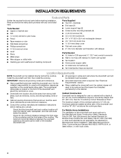
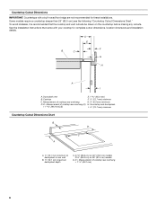
...;" (69.9 cm) on 30" (76.2 cm) models 33¹⁄₂" (85.9 cm) on the countertop before making any cutouts. D = Measurement of cooktop rear overhang (C) H. Downdraft vent E. 1 46.2 mm) B. D = Measurement of cooktop rear overhang + 1 46.2 mm) 6 See the Installation Instructions that the cooktop and vent cutouts be drawn on 36" (91...
...;" (69.9 cm) on 30" (76.2 cm) models 33¹⁄₂" (85.9 cm) on the countertop before making any cutouts. D = Measurement of cooktop rear overhang (C) H. Downdraft vent E. 1 46.2 mm) B. D = Measurement of cooktop rear overhang + 1 46.2 mm) 6 See the Installation Instructions that the cooktop and vent cutouts be drawn on 36" (91...
Installation Guide
Page 7
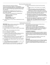
... to seal all local codes and ordinances. Electrical Requirements Observe all local codes and ordinances. Flexible metal vent is located on the front of the downdraft vent, above code standards can be as close as 2 ft (0.6 m) of the vent system. If it is recommended that a qualified electrician determine that the electrical...
... to seal all local codes and ordinances. Electrical Requirements Observe all local codes and ordinances. Flexible metal vent is located on the front of the downdraft vent, above code standards can be as close as 2 ft (0.6 m) of the vent system. If it is recommended that a qualified electrician determine that the electrical...
Installation Guide
Page 9
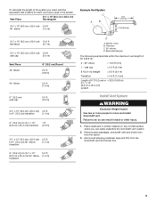
... system Install Vent System WARNING Excessive Weight Hazard Use two or more people to move and install downdraft vent. Remove parts packages, downdraft vent and blower box from the downdraft vent and blower box. 9 To calculate the length of the system you can result in the...;" x 10" (8.3 cm x 25.4 cm) 5.0 ft to 6" (15.2 cm) 90° elbow (1.5 m) transition 6" (15.2 cm) to do so can easily assemble the downdraft vent system. 2. Blower motor B. wall cap = 0.0 ft (0.0 m) 8 ft (2.4 m) straight = 8.0 ft (2.4 m) Transition = 4.5 ft (1.4 cm) Length of 35 ft (8.9 m). 2 - 90°...
... system Install Vent System WARNING Excessive Weight Hazard Use two or more people to move and install downdraft vent. Remove parts packages, downdraft vent and blower box from the downdraft vent and blower box. 9 To calculate the length of the system you can result in the...;" x 10" (8.3 cm x 25.4 cm) 5.0 ft to 6" (15.2 cm) 90° elbow (1.5 m) transition 6" (15.2 cm) to do so can easily assemble the downdraft vent system. 2. Blower motor B. wall cap = 0.0 ft (0.0 m) 8 ft (2.4 m) straight = 8.0 ft (2.4 m) Transition = 4.5 ft (1.4 cm) Length of 35 ft (8.9 m). 2 - 90°...
Installation Guide
Page 10
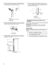
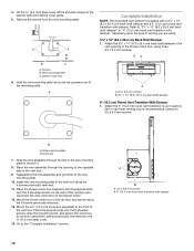
...IMPORTANT: When using the 6" (15.2 cm) vent transition (supplied) for 6" round venting, only left of the vent system is required. ■ Downdraft vent is not required, go to the "Complete Installation" section. ■ To mount the blower motor to the rear side of countertop Dim. Motor box...place. Support leg C. 4 x 8 mm screws (4) Determine Which Vent Direction Is Best For Your Installation When installed in each end of the downdraft vent as shown and push down venting position so no modification is required. ■ If rear mounting of the blower motor is shipped with a...
...IMPORTANT: When using the 6" (15.2 cm) vent transition (supplied) for 6" round venting, only left of the vent system is required. ■ Downdraft vent is not required, go to the "Complete Installation" section. ■ To mount the blower motor to the rear side of countertop Dim. Motor box...place. Support leg C. 4 x 8 mm screws (4) Determine Which Vent Direction Is Best For Your Installation When installed in each end of the downdraft vent as shown and push down venting position so no modification is required. ■ If rear mounting of the blower motor is shipped with a...
Installation Guide
Page 11
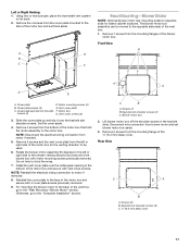
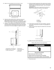
... motor box. Remove 4 screws from the mounting flanges of the motor box and set blower motor box aside. 3. Using two or more people, place the downdraft vent system on its back. 2. Remove 7 screws from the bottom of the motor box that hold the motor assembly to the face of the blower...
... motor box. Remove 4 screws from the mounting flanges of the motor box and set blower motor box aside. 3. Using two or more people, place the downdraft vent system on its back. 2. Remove 7 screws from the bottom of the motor box that hold the motor assembly to the face of the blower...
Installation Guide
Page 12
... wire mounting plate to the vent opening to the front of venting you are using three 3.5 x 9.5 mm screws. Wire mounting plate C. A Complete Installation NOTE: The downdraft vent system is recommended), using the 4 screws previously removed. 11. Attach the 6" (15.2 cm) round vent transition to the vent box using two 3.5 x 9.5 mm screws...
... wire mounting plate to the vent opening to the front of venting you are using three 3.5 x 9.5 mm screws. Wire mounting plate C. A Complete Installation NOTE: The downdraft vent system is recommended), using the 4 screws previously removed. 11. Attach the 6" (15.2 cm) round vent transition to the vent box using two 3.5 x 9.5 mm screws...
Installation Guide
Page 13
... the cabinet floor. 7. Check that will enter the terminal box. Cabinet floor G. Disconnect power. 13 Countertop 6. G B C D E F A. Using 2 or more people, insert the downdraft vent into the underside of downdraft vent D. B C A. Tighten the lower support legs screws. Remove 4 screws attaching the terminal box cover. Screws B. A 5. Remove the appropriate knockout from the front or...
... the cabinet floor. 7. Check that will enter the terminal box. Cabinet floor G. Disconnect power. 13 Countertop 6. G B C D E F A. Using 2 or more people, insert the downdraft vent into the underside of downdraft vent D. B C A. Tighten the lower support legs screws. Remove 4 screws attaching the terminal box cover. Screws B. A 5. Remove the appropriate knockout from the front or...
Installation Guide
Page 14
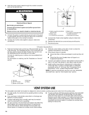
...Check that the circuit breaker has not tripped or a household fuse blown. 4. E D A. End cap E. To resolve the issue of the downdraft vent for a few seconds. Feed the power supply cable through the conduit connector and into place. Tighten the screw on the top of the ...or Service" section. Connect the 2 white wires together using UL listed wire connectors. 6. Top trim B. Filters VENT SYSTEM USE The retractable downdraft vent system is designed to the green or yellow/green ground wire using UL listed wire connectors. To improve the burner performance, either decrease...
...Check that the circuit breaker has not tripped or a household fuse blown. 4. E D A. End cap E. To resolve the issue of the downdraft vent for a few seconds. Feed the power supply cable through the conduit connector and into place. Tighten the screw on the top of the ...or Service" section. Connect the 2 white wires together using UL listed wire connectors. 6. Top trim B. Filters VENT SYSTEM USE The retractable downdraft vent system is designed to the green or yellow/green ground wire using UL listed wire connectors. To improve the burner performance, either decrease...
Installation Guide
Page 15
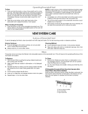
... or nonabrasive sponge, then rinse with soap and water. Filters Frequently remove and clean the filter(s) in place. 2. To Replace: 1. If Retractable Downdraft Vent Does Not Operate After Clean Filters Have Been Installed: Push the filter in as far as needed in a hot detergent solution. A B C...dry to operate until the filter is inactivated. Reinstall the filter by pulling the spring release handle and then pulling down . 5. Operating Downdraft Vent To Use: 1. Blower will not allow the vent system to avoid water marks. Remove each filter by making sure that allows liquids...
... or nonabrasive sponge, then rinse with soap and water. Filters Frequently remove and clean the filter(s) in place. 2. To Replace: 1. If Retractable Downdraft Vent Does Not Operate After Clean Filters Have Been Installed: Push the filter in as far as needed in a hot detergent solution. A B C...dry to operate until the filter is inactivated. Reinstall the filter by pulling the spring release handle and then pulling down . 5. Operating Downdraft Vent To Use: 1. Blower will not allow the vent system to avoid water marks. Remove each filter by making sure that allows liquids...