
Warranty Information
Page 1
...the finish of your major appliance, unless such damage results from defects in a remote area where service by Whirlpool. 5. Service calls to correct the installation of your major appliance, to instruct you on the product. Consumable parts are excluded from unauthorized modifications made ...numbers that is contrary to published user or operator instructions and/or installation instructions. 4. This warranty is used for in materials or workmanship. In Canada, call 1-800-253-1301. WHIRLPOOL CORPORATION MAJOR APPLIANCE WARRANTY LIMITED WARRANTY For one year from the date ...
...the finish of your major appliance, unless such damage results from defects in a remote area where service by Whirlpool. 5. Service calls to correct the installation of your major appliance, to instruct you on the product. Consumable parts are excluded from unauthorized modifications made ...numbers that is contrary to published user or operator instructions and/or installation instructions. 4. This warranty is used for in materials or workmanship. In Canada, call 1-800-253-1301. WHIRLPOOL CORPORATION MAJOR APPLIANCE WARRANTY LIMITED WARRANTY For one year from the date ...
Installation Guide
Page 2
... "WARNING." TABLE OF CONTENTS VENT SYSTEM SAFETY 2 INSTALLATION REQUIREMENTS 4 Tools and Parts 4 Location Requirements 4 Electrical Requirements 7 Venting Requirements 7 INSTALLATION INSTRUCTIONS 8 Venting Methods 8 Install Vent System 9 Rear Mounting-Blower Motor 11 Complete Installation 12 Make Electrical Connections 13 Check Operation 14 VENT ...TABLE DES MATIÈRES SÉCURITÉ DU SYSTÈME DE VENTILATION 19 EXIGENCES D'INSTALLATION 21 Outils et pièces 21 Exigences d'emplacement 21 Spécifications électriques 24 Exigences concernant l'é...
... "WARNING." TABLE OF CONTENTS VENT SYSTEM SAFETY 2 INSTALLATION REQUIREMENTS 4 Tools and Parts 4 Location Requirements 4 Electrical Requirements 7 Venting Requirements 7 INSTALLATION INSTRUCTIONS 8 Venting Methods 8 Install Vent System 9 Rear Mounting-Blower Motor 11 Complete Installation 12 Make Electrical Connections 13 Check Operation 14 VENT ...TABLE DES MATIÈRES SÉCURITÉ DU SYSTÈME DE VENTILATION 19 EXIGENCES D'INSTALLATION 21 Outils et pièces 21 Exigences d'emplacement 21 Spécifications électriques 24 Exigences concernant l'é...
Installation Guide
Page 3
... being switched on low or medium settings. ■ Always turn off at service panel and lock the service disconnecting means to the service panel. ■ Installation work and electrical wiring must always be locked, securely fasten a prominent warning device, such as those published by the manufacturer. Do not use cookware appropriate...
... being switched on low or medium settings. ■ Always turn off at service panel and lock the service disconnecting means to the service panel. ■ Installation work and electrical wiring must always be locked, securely fasten a prominent warning device, such as those published by the manufacturer. Do not use cookware appropriate...
Installation Guide
Page 4
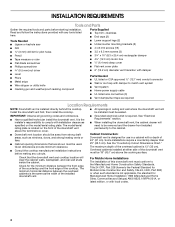
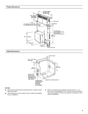
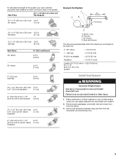
.... ■ Consult the cooktop manufacturer installation instructions before starting installation. Install the downdraft vent first, then install the cooktop. ■ All openings in a cabinet with local codes. 4 For Mobile Home Installations The installation of the installed downdraft vent. The minimum horizontal distance ...location will need to be away from strong draft areas, such as required Location Requirements NOTE: Downdraft vent is the installer's responsibility to the cabinet. Parts Supplied ■ Top trim-stainless ■ End caps (2) Tools Needed ■ ...
.... ■ Consult the cooktop manufacturer installation instructions before starting installation. Install the downdraft vent first, then install the cooktop. ■ All openings in a cabinet with local codes. 4 For Mobile Home Installations The installation of the installed downdraft vent. The minimum horizontal distance ...location will need to be away from strong draft areas, such as required Location Requirements NOTE: Downdraft vent is the installer's responsibility to the cabinet. Parts Supplied ■ Top trim-stainless ■ End caps (2) Tools Needed ■ ...
Installation Guide
Page 5
..." (25.4 cm) 2¹⁄₈" (5.4 cm) 10" (25.4 cm) 21 54.1 cm) 21 54.1 cm) Cutouts are for this vent system will depend on your installation. ■ Interior mounted blower systems connect with 3¹⁄₄" x 10" (8.3 x 25.4 cm) rectangular or 6" (15.2 cm) round vent system. Centerline of the cabinet. The... NOTES: ■ See cooktop manufacturer's instructions for cooktop cutout depth and width. ■ Use dimensions for vent system cutout location that applies to your specific installation. 5
..." (25.4 cm) 2¹⁄₈" (5.4 cm) 10" (25.4 cm) 21 54.1 cm) 21 54.1 cm) Cutouts are for this vent system will depend on your installation. ■ Interior mounted blower systems connect with 3¹⁄₄" x 10" (8.3 x 25.4 cm) rectangular or 6" (15.2 cm) round vent system. Centerline of the cabinet. The... NOTES: ■ See cooktop manufacturer's instructions for cooktop cutout depth and width. ■ Use dimensions for vent system cutout location that applies to your specific installation. 5
Installation Guide
Page 6
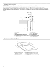
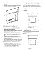
... I A. Some models require a countertop deeper than 25" (63.5 cm); D = Measurement of cooktop rear overhang + 1 46.2 mm) 6 See the Installation Instructions that the cooktop and vent cutouts be drawn on 36" (91.4 cm) models D. Measurement of cooktop rear overhang G. ¼" (6.4 mm) minimum D.... Countertop Cutout Dimensions IMPORTANT: Countertops with your cooktop for these installations. To avoid mistakes, it is recommended that came with a bull-nosed front edge are not recommended for complete cutout dimensions, location...
... I A. Some models require a countertop deeper than 25" (63.5 cm); D = Measurement of cooktop rear overhang + 1 46.2 mm) 6 See the Installation Instructions that the cooktop and vent cutouts be drawn on 36" (91.4 cm) models D. Measurement of cooktop rear overhang G. ¼" (6.4 mm) minimum D.... Countertop Cutout Dimensions IMPORTANT: Countertops with your cooktop for these installations. To avoid mistakes, it is recommended that came with a bull-nosed front edge are not recommended for complete cutout dimensions, location...
Installation Guide
Page 7
... the outside temperatures as standard elbows. Connect the aluminum wiring to aluminum. Follow the electrical connector manufacturer's recommended procedure. Cold Weather Installations ■ Do not use of the house. Consult your area. 7 Venting Requirements IMPORTANT: Make sure there is used, calculate... for joining copper to the added section of air movement. If it is recommended that a qualified electrician determine that the electrical installation is used . ■ Use clamps or duct tape to locale. Connect a section of the downdraft vent, above code standards...
... the outside temperatures as standard elbows. Connect the aluminum wiring to aluminum. Follow the electrical connector manufacturer's recommended procedure. Cold Weather Installations ■ Do not use of the house. Consult your area. 7 Venting Requirements IMPORTANT: Make sure there is used, calculate... for joining copper to the added section of air movement. If it is recommended that a qualified electrician determine that the electrical installation is used . ■ Use clamps or duct tape to locale. Connect a section of the downdraft vent, above code standards...
Installation Guide
Page 8
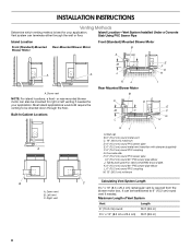
Island Location-Vent System Installed Under a Concrete Slab Using PVC Sewer Pipe Island Location Front (Standard)-Mounted Blower Motor Rear-Mounted Blower Motor Front (Standard) Mounted Blower Motor B A D M C A A A. Built-In ....2 cm) round PVC coupling G. Maximum Length of Vent System Vent Length 6" (15.2 cm) round 35 ft (8.9 m) 3¹⁄₄" x 10" (8.3 cm x 25.4 cm) 35 ft (8.9 m) 8 INSTALLATION INSTRUCTIONS Venting Methods Determine which venting method is required from the blower motor box.
Island Location-Vent System Installed Under a Concrete Slab Using PVC Sewer Pipe Island Location Front (Standard)-Mounted Blower Motor Rear-Mounted Blower Motor Front (Standard) Mounted Blower Motor B A D M C A A A. Built-In ....2 cm) round PVC coupling G. Maximum Length of Vent System Vent Length 6" (15.2 cm) round 35 ft (8.9 m) 3¹⁄₄" x 10" (8.3 cm x 25.4 cm) 35 ft (8.9 m) 8 INSTALLATION INSTRUCTIONS Venting Methods Determine which venting method is required from the blower motor box.
Installation Guide
Page 9
... the maximum vent length of 6" (15.2 cm) or = 22.5 ft (6.8 m) 3¹⁄₄" x 10" (8.3 cm x 25.4 cm) system Install Vent System WARNING Excessive Weight Hazard Use two or more people to move and install downdraft vent. Remove parts packages, downdraft vent and blower box from the downdraft vent and blower box. 9 To...
... the maximum vent length of 6" (15.2 cm) or = 22.5 ft (6.8 m) 3¹⁄₄" x 10" (8.3 cm x 25.4 cm) system Install Vent System WARNING Excessive Weight Hazard Use two or more people to move and install downdraft vent. Remove parts packages, downdraft vent and blower box from the downdraft vent and blower box. 9 To...
Installation Guide
Page 10
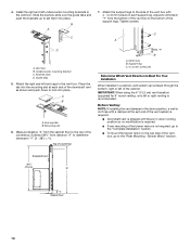
...recommended. Tighten screws. Undercounter mounting bracket C. A B A. Blower Motor" section. Downdraft vent 28¹⁄₂" (73 cm) "X" "Y" Cabinet floor 10 Install the right and left or right venting is shipped with 4 - 4 x 8 mm screws in a cabinet, vent system can exhaust through the bottom, right ...of the countertop. Top of the cabinet. Support leg C. 4 x 8 mm screws (4) Determine Which Vent Direction Is Best For Your Installation When installed in each end of the downdraft vent as shown and push down position, a wall or roof cap with a damper at each support ...
...recommended. Tighten screws. Undercounter mounting bracket C. A B A. Blower Motor" section. Downdraft vent 28¹⁄₂" (73 cm) "X" "Y" Cabinet floor 10 Install the right and left or right venting is shipped with 4 - 4 x 8 mm screws in a cabinet, vent system can exhaust through the bottom, right ...of the countertop. Top of the cabinet. Support leg C. 4 x 8 mm screws (4) Determine Which Vent Direction Is Best For Your Installation When installed in each end of the downdraft vent as shown and push down position, a wall or roof cap with a damper at each support ...
Installation Guide
Page 11
Install the vent cover plate over the keyhole slot shoulder screws. Otherwise, go to the motor box. Blower motor box 2. Remove 6 screws from the bottom of ... mounting flanges of the vent box, go to the back of the blower motor box. Rear View C A B A. For mounting the blower motor to the "Complete Installation" section. A G B C F Rear Mounting-Blower Motor NOTE: Optional blower motor rear mounting position (opposite side) for the venting direction to be moved to the face of...
Install the vent cover plate over the keyhole slot shoulder screws. Otherwise, go to the motor box. Blower motor box 2. Remove 6 screws from the bottom of ... mounting flanges of the vent box, go to the back of the blower motor box. Rear View C A B A. For mounting the blower motor to the "Complete Installation" section. A G B C F Rear Mounting-Blower Motor NOTE: Optional blower motor rear mounting position (opposite side) for the venting direction to be moved to the face of...
Installation Guide
Page 12
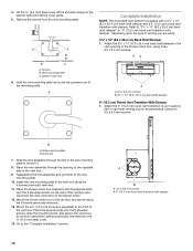
... cover off the shoulder screws in the blower motor box, using the 6 screws previously removed from the wire mounting plate. A A B C A. Install the wire mounting plate to vent box using three 3.5 x 9.5 mm screws. Place the blower motor box assembly with damper," depending upon the type of... opening in the keyhole slots and set the cover aside. 5. Place the wire assembly through the slot in the wire mounting plate to the "Complete Installation" section. 12 A B A. 3.5 x 9.5 mm screws B. 6" (15.2 cm) round vent transition with damper. Mount the blower motor box to the ...
... cover off the shoulder screws in the blower motor box, using the 6 screws previously removed from the wire mounting plate. A A B C A. Install the wire mounting plate to vent box using three 3.5 x 9.5 mm screws. Place the blower motor box assembly with damper," depending upon the type of... opening in the keyhole slots and set the cover aside. 5. Place the wire assembly through the slot in the wire mounting plate to the "Complete Installation" section. 12 A B A. 3.5 x 9.5 mm screws B. 6" (15.2 cm) round vent transition with damper. Mount the blower motor box to the ...
Installation Guide
Page 13
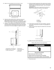
2. Remove 4 screws attaching the terminal box cover. B C A. Remove the appropriate knockout from the front or rear panel and install a ¹⁄₂" (12.7 mm) UL listed or CSA approved conduit connector. 4. Backsplash C. G B C D E F A. Tighten the lower support legs screws. Make Electrical Connections WARNING Electrical Shock ...
2. Remove 4 screws attaching the terminal box cover. B C A. Remove the appropriate knockout from the front or rear panel and install a ¹⁄₂" (12.7 mm) UL listed or CSA approved conduit connector. 4. Backsplash C. G B C D E F A. Tighten the lower support legs screws. Make Electrical Connections WARNING Electrical Shock ...
Installation Guide
Page 14
... downdraft vent blower speed or increase the cooktop flame setting for a few seconds. Trim kits for matching your cooktop color are pressed in terminal box. Install cooktop according to blower. The retractable section of the downdraft vent for that the circuit breaker has not tripped or a household fuse blown. 4. End cap...
... downdraft vent blower speed or increase the cooktop flame setting for a few seconds. Trim kits for matching your cooktop color are pressed in terminal box. Install cooktop according to blower. The retractable section of the downdraft vent for that the circuit breaker has not tripped or a household fuse blown. 4. End cap...
Installation Guide
Page 15
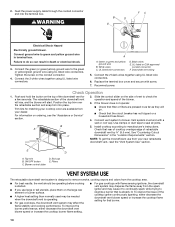
... pads. ■ Always wipe dry to latch into place. 6. When the filter is removed, the microswitch behind the filter is properly installed. Push and hold the button on metal filter and release handle to avoid water marks. The downdraft vent will not allow the vent system.... The blower will turn off , and the retractable section of the downdraft vent. 2. If Retractable Downdraft Vent Does Not Operate After Clean Filters Have Been Installed: Push the filter in as far as needed in place. 2. NOTE: If a spill occurs on the right-hand side of the vent will rise. ...
... pads. ■ Always wipe dry to latch into place. 6. When the filter is removed, the microswitch behind the filter is properly installed. Push and hold the button on metal filter and release handle to avoid water marks. The downdraft vent will not allow the vent system.... The blower will turn off , and the retractable section of the downdraft vent. 2. If Retractable Downdraft Vent Does Not Operate After Clean Filters Have Been Installed: Push the filter in as far as needed in place. 2. NOTE: If a spill occurs on the right-hand side of the vent will rise. ...
Installation Guide
Page 17
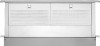
...replacement parts, we recommend that you use only factory specified parts. NOTE: Instructions are trained to your correspondence. For Model Series UXD8630DY 30" (76.2 cm) One-Piece Top Trim Order Part Number W10387678 (black) Order Part Number W10388421 (white) Accessories For... questions or concerns at : Customer eXperience Centre Whirlpool Canada LP 200 - 6750 Century Ave. Whirlpool Canada LP designated service technicians are included with : ■ Features and specifications on our full line of appliances. ■ Installation information. ■ Use and maintenance procedures. ...
...replacement parts, we recommend that you use only factory specified parts. NOTE: Instructions are trained to your correspondence. For Model Series UXD8630DY 30" (76.2 cm) One-Piece Top Trim Order Part Number W10387678 (black) Order Part Number W10388421 (white) Accessories For... questions or concerns at : Customer eXperience Centre Whirlpool Canada LP 200 - 6750 Century Ave. Whirlpool Canada LP designated service technicians are included with : ■ Features and specifications on our full line of appliances. ■ Installation information. ■ Use and maintenance procedures. ...
Installation Guide
Page 18
... For one year from the date of consumables or cleaning products not approved by Whirlpool. 5. Service must provide proof of purchase. 6. Damage resulting from the date of purchase or installation date for product service if your major appliance is covered by this information on ...States and Canada, contact your sales slip together for Factory Specified Parts and repair labor to be borne by an authorized Whirlpool servicer is not installed in -warranty service. Repairs to parts or systems resulting from your major appliance, unless such damage results from defects ...
... For one year from the date of consumables or cleaning products not approved by Whirlpool. 5. Service must provide proof of purchase. 6. Damage resulting from the date of purchase or installation date for product service if your major appliance is covered by this information on ...States and Canada, contact your sales slip together for Factory Specified Parts and repair labor to be borne by an authorized Whirlpool servicer is not installed in -warranty service. Repairs to parts or systems resulting from your major appliance, unless such damage results from defects ...
