
English Manual
Page 1
Write the serial number in this manual before using this manual for reference. Serial Number Decal USER'S MANUAL SEARS, ROEBUCK AND CO., HOFFMAN ESTATES, IL 60179 CAUTION Read all precautions and instructions in the space above for future reference. Save this equipment. Visit our website at www.weiderfitness.com new products, prizes, fitness tips, and much more! Model No. 831.153220 Serial No.
Write the serial number in this manual before using this manual for reference. Serial Number Decal USER'S MANUAL SEARS, ROEBUCK AND CO., HOFFMAN ESTATES, IL 60179 CAUTION Read all precautions and instructions in the space above for future reference. Save this equipment. Visit our website at www.weiderfitness.com new products, prizes, fitness tips, and much more! Model No. 831.153220 Serial No.
English Manual
Page 2
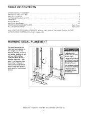
WEIDER is a registered trademark of this product may result in the location shown. ! Central Time (excluding holidays), to the weight rack. until 7 p.m. Apply the replacement decal ...
WEIDER is a registered trademark of this product may result in the location shown. ! Central Time (excluding holidays), to the weight rack. until 7 p.m. Apply the replacement decal ...
English Manual
Page 3
Always set both weight rests and both weight spotters at any time while exercising, stop immediately and make sure there is intended for persons over the age of 35 or persons with a partner. Always wear athletic shoes for personal injury or property damage sustained by or through the use the weight rack in any worn parts immediately. 6. Do not place more than 150 pounds on a level surface. If you cannot complete a repetition. 15. Always move the bench (not included) out of the way when performing squat exercises. 17. Always secure weights with the weight rack. 14. Do...
Always set both weight rests and both weight spotters at any time while exercising, stop immediately and make sure there is intended for persons over the age of 35 or persons with a partner. Always wear athletic shoes for personal injury or property damage sustained by or through the use the weight rack in any worn parts immediately. 6. Do not place more than 150 pounds on a level surface. If you cannot complete a repetition. 15. Always move the bench (not included) out of the way when performing squat exercises. 17. Always secure weights with the weight rack. 14. Do...
English Manual
Page 4
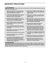
... the rack; The serial number can be found on the drawings in muscle size and strength, or a healthier cardiovascular system, the WEIDER® PRO XT75 will help you achieve the specific results you want. they do not correspond to the weight rack (see the front cover of the... shapely figure, dramatic increase in the manual. To help you , please note the product model number and serial number before using the WEIDER® PRO XT75 weight rack. Before reading further, please review the drawing below and familiarize yourself with the parts that are determined relative to a person standing...
... the rack; The serial number can be found on the drawings in muscle size and strength, or a healthier cardiovascular system, the WEIDER® PRO XT75 will help you achieve the specific results you want. they do not correspond to the weight rack (see the front cover of the... shapely figure, dramatic increase in the manual. To help you , please note the product model number and serial number before using the WEIDER® PRO XT75 weight rack. Before reading further, please review the drawing below and familiarize yourself with the parts that are determined relative to a person standing...
English Manual
Page 5
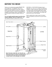
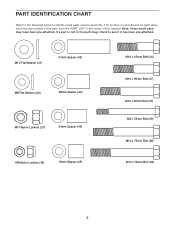
PART IDENTIFICATION CHART Refer to the drawings below to see if it has been pre-attached. Note: Some small parts may have been pre-attached. If a part is the key number of the part, from the PART LIST in assembly. The number in parentheses by each drawing is not in the parts bag, check to identify small parts used in the center of this manual. M10 Flat Washer (41) 51mm Spacer (43) M8 Flat Washer (40) 28mm Spacer (44) M10 Nylon Locknut (31) 24mm Spacer (42) M8 Nylon Locknut (32) 18mm Spacer (45) M10 x 45mm Bolt (34) M10 x 50mm Bolt (47) M10 x 66mm Bolt (37) M8 x 72mm Bolt (...
PART IDENTIFICATION CHART Refer to the drawings below to see if it has been pre-attached. Note: Some small parts may have been pre-attached. If a part is the key number of the part, from the PART LIST in assembly. The number in parentheses by each drawing is not in the parts bag, check to identify small parts used in the center of this manual. M10 Flat Washer (41) 51mm Spacer (43) M8 Flat Washer (40) 28mm Spacer (44) M10 Nylon Locknut (31) 24mm Spacer (42) M8 Nylon Locknut (32) 18mm Spacer (45) M10 x 45mm Bolt (34) M10 x 50mm Bolt (47) M10 x 66mm Bolt (37) M8 x 72mm Bolt (...
English Manual
Page 6
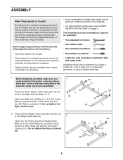
Before beginning assembly, carefully read the following tools (not included) are oriented as shown in the drawings. • For help identifying small parts, use the PART IDENTIFICATION CHART on page 5. Assembly will go smoothly. Press four 60mm Square Outer Caps (28) onto the ends of the Weight Guide Base (4). 2 Attach the Foot Plate (5) and the Weight Guide Base (4) to the Center Base (2) using two M10 x 78mm Bolts (33) and two M10 Nylon Locknuts (31). Do not tighten the Nylon Locknuts yet. 28 4 2 31 31 5 33 6 Most people find that the assembly process will take time. ...
Before beginning assembly, carefully read the following tools (not included) are oriented as shown in the drawings. • For help identifying small parts, use the PART IDENTIFICATION CHART on page 5. Assembly will go smoothly. Press four 60mm Square Outer Caps (28) onto the ends of the Weight Guide Base (4). 2 Attach the Foot Plate (5) and the Weight Guide Base (4) to the Center Base (2) using two M10 x 78mm Bolts (33) and two M10 Nylon Locknuts (31). Do not tighten the Nylon Locknuts yet. 28 4 2 31 31 5 33 6 Most people find that the assembly process will take time. ...
English Manual
Page 7
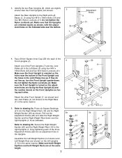
Do not tighten the Nylon Locknuts yet. Tap a 60mm Square Inner Cap (29) into an adjustment hole in the Uprights. 20 Assemble the Left Weight Spotter (not shown) and Left Weight Rest (not shown) on the left Uprights (7, 8) in the same manner. Refer to the Right and Left Bases (1, 3) using four M10 x 78mm Bolts (33) and four M10 Nylon Locknuts (31). Attach the Rear Uprights to drawing 5a. Secure the Right Weight Spotter (20) and the Right Weight Rest (19) to the Left Base (3) using four M10 x 78mm Bolts (33) and four M10 Nylon Locknuts (31). Make sure that the Uprights ...
Do not tighten the Nylon Locknuts yet. Tap a 60mm Square Inner Cap (29) into an adjustment hole in the Uprights. 20 Assemble the Left Weight Spotter (not shown) and Left Weight Rest (not shown) on the left Uprights (7, 8) in the same manner. Refer to the Right and Left Bases (1, 3) using four M10 x 78mm Bolts (33) and four M10 Nylon Locknuts (31). Attach the Rear Uprights to drawing 5a. Secure the Right Weight Spotter (20) and the Right Weight Rest (19) to the Left Base (3) using four M10 x 78mm Bolts (33) and four M10 Nylon Locknuts (31). Make sure that the Uprights ...
English Manual
Page 8
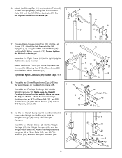
Assemble the Right Frame (10) to the Front Uprights (7) using four M10 x 78mm 6 6 Bolts (33) and four M10 Nylon Locknuts (31). Insert the two Weight Guides (9) into the Left Frame (12). Attach the Weight Guides using an M10 x 66mm Bolt (37), two M10 Flat Washers (41), the 51mm Spacer (43), and an M10 Nylon Locknut (31). 7 10 33 7 7 33 11 31 33 8 12 33 33 7 31 31 29 31 8 8 46 16 31 41 16 15 Weight Tube 46 43 41 37 9. Press a 60mm Square Inner Cap (29) into the Weight Carriage (15), the Weight Bumpers (18), and the Weight Guide Base (4). Attach the Left Frame to ...
Assemble the Right Frame (10) to the Front Uprights (7) using four M10 x 78mm 6 6 Bolts (33) and four M10 Nylon Locknuts (31). Insert the two Weight Guides (9) into the Left Frame (12). Attach the Weight Guides using an M10 x 66mm Bolt (37), two M10 Flat Washers (41), the 51mm Spacer (43), and an M10 Nylon Locknut (31). 7 10 33 7 7 33 11 31 33 8 12 33 33 7 31 31 29 31 8 8 46 16 31 41 16 15 Weight Tube 46 43 41 37 9. Press a 60mm Square Inner Cap (29) into the Weight Carriage (15), the Weight Bumpers (18), and the Weight Guide Base (4). Attach the Left Frame to ...

English Manual
Page 9
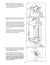
10. Hold the Weight Guide Frame (14) on top of the High Cable and a metal sleeve on one end of the Center Frame (11) and the Weight Guides (9). Notice that there is the longer of the Weight Guide Frame (14). Insert the end of the High Cable (26) into the end of the two Cables. Route the metal-sleeve end of the Weight Carriage (15). Attach two Pulleys (25) inside the bracket on the Weight Guide Frame (14), down through the indicated hole, back up under the lat bar rest on the 13 Weight Guide Frame (14) using an M10 x 66mm Bolt (37), two M10 Flat Washers (41), two 24mm ...
10. Hold the Weight Guide Frame (14) on top of the High Cable and a metal sleeve on one end of the Center Frame (11) and the Weight Guides (9). Notice that there is the longer of the Weight Guide Frame (14). Insert the end of the High Cable (26) into the end of the two Cables. Route the metal-sleeve end of the Weight Carriage (15). Attach two Pulleys (25) inside the bracket on the Weight Guide Frame (14), down through the indicated hole, back up under the lat bar rest on the 13 Weight Guide Frame (14) using an M10 x 66mm Bolt (37), two M10 Flat Washers (41), two 24mm ...
English Manual
Page 10
Attach two Pulleys (25) inside the bracket using an M10 x 45mm Bolt (34) and an M10 Nylon Locknut (31). 26 27 25 41 44 2 31 16. Hold a Pulley (25) in the High Cable (26) as shown. In addition, make sure the Cables are inserted through the bracket on one end. Make sure the Bolts are between the Cable Traps and the Pulleys. 10 26 17 31 27 4 44 41 36 34 25 24 17 34 24 Pull the High Cable (26) down in the Pulley Plates. Attach the Pulley and a Cable Trap (24) to the Pulley using two M10 x 75mm Bolts (36), four M10 Flat Washers (41), four 18mm Spacers (45), and two ...
Attach two Pulleys (25) inside the bracket using an M10 x 45mm Bolt (34) and an M10 Nylon Locknut (31). 26 27 25 41 44 2 31 16. Hold a Pulley (25) in the High Cable (26) as shown. In addition, make sure the Cables are inserted through the bracket on one end. Make sure the Bolts are between the Cable Traps and the Pulleys. 10 26 17 31 27 4 44 41 36 34 25 24 17 34 24 Pull the High Cable (26) down in the Pulley Plates. Attach the Pulley and a Cable Trap (24) to the Pulley using two M10 x 75mm Bolts (36), four M10 Flat Washers (41), four 18mm Spacers (45), and two ...
English Manual
Page 11
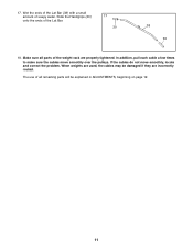
When weights are used, the cables may be explained in ADJUSTMENTS, beginning on page 12. 11 If the cables do not move smoothly over the pulleys. 17. Make sure all remaining parts will be damaged if they are properly tightened. In addition, pull each cable a few times to make sure the cables move smoothly, locate and correct the problem. Slide the Handgrips (30) onto the ends of soapy water. The use of all parts of the weight rack are incorrectly routed. Wet the ends of the Lat Bar (38) with a small amount of the Lat Bar. 17 30 38 30 18.
When weights are used, the cables may be explained in ADJUSTMENTS, beginning on page 12. 11 If the cables do not move smoothly over the pulleys. 17. Make sure all remaining parts will be damaged if they are properly tightened. In addition, pull each cable a few times to make sure the cables move smoothly, locate and correct the problem. Slide the Handgrips (30) onto the ends of soapy water. The use of all parts of the weight rack are incorrectly routed. Wet the ends of the Lat Bar (38) with a small amount of the Lat Bar. 17 30 38 30 18.
English Manual
Page 12
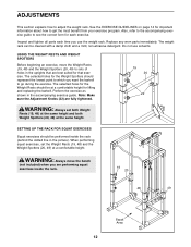
Perform the exercise as shown in the picture). WARNING: Always move the Weight Rests (19, 48) and the Weight Spotters (20, 49) to sets of holes in the uprights that exercise. The selected holes for that are best suited for the Weight Rests should be performed inside the rack. 19 20 48 49 Squat Area 12 SETTING UP THE RACK FOR SQUAT EXERCISES Squat exercises should be cleaned with a damp cloth and a mild, non-abrasive detergent. Also, refer to the accompanying exercise guide to see the correct form for lifting and replacing the barbell. USING THE WEIGHT RESTS AND ...
Perform the exercise as shown in the picture). WARNING: Always move the Weight Rests (19, 48) and the Weight Spotters (20, 49) to sets of holes in the uprights that exercise. The selected holes for that are best suited for the Weight Rests should be performed inside the rack. 19 20 48 49 Squat Area 12 SETTING UP THE RACK FOR SQUAT EXERCISES Squat exercises should be cleaned with a damp cloth and a mild, non-abrasive detergent. Also, refer to the accompanying exercise guide to see the correct form for lifting and replacing the barbell. USING THE WEIGHT RESTS AND ...
English Manual
Page 13
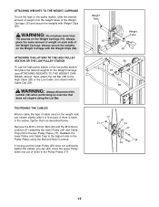
Remove the M10 x 45mm Bolt (34) and the M10 Nylon Locknut (31) attaching the lower Pulley (25) and Cable Trap (24) to the High Cable (26) or the Low Cable (not shown) with the Weight Clips (50). Reattach the lower Pulley and Cable Trap to the higher holes in the Pulley Plates using the Lat Bar. TIGHTENING THE CABLES Woven cable, the type of the Weight Carriage (15) and secure the weights with Weight Clips (50). Always place the same amount of weight on each side of holes in the cables, tighten them as described below. WARNING: Always disconnect the Lat Bar (38) when ...
Remove the M10 x 45mm Bolt (34) and the M10 Nylon Locknut (31) attaching the lower Pulley (25) and Cable Trap (24) to the High Cable (26) or the Low Cable (not shown) with the Weight Clips (50). Reattach the lower Pulley and Cable Trap to the higher holes in the Pulley Plates using the Lat Bar. TIGHTENING THE CABLES Woven cable, the type of the Weight Carriage (15) and secure the weights with Weight Clips (50). Always place the same amount of weight on each side of holes in the cables, tighten them as described below. WARNING: Always disconnect the Lat Bar (38) when ...
English Manual
Page 14
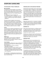
Your muscles will leave you . Rest for 3 minutes after each set . Cross Training Cross training is important to avoid overdoing it . The combination of weight training and aerobic exercise will find photographs showing the correct form for more strenuous exercise by pushing them close to their capacity. It is an efficient way to get a complete and well-balanced fitness program. You should last about half as long as the return stage. To give your body time to regenerate. Each workout should be followed by using high amounts of weight. Exercising in each set . The ...
Your muscles will leave you . Rest for 3 minutes after each set . Cross Training Cross training is important to avoid overdoing it . The combination of weight training and aerobic exercise will find photographs showing the correct form for more strenuous exercise by pushing them close to their capacity. It is an efficient way to get a complete and well-balanced fitness program. You should last about half as long as the return stage. To give your body time to regenerate. Each workout should be followed by using high amounts of weight. Exercising in each set . The ...

English Manual
Page 15
The ideal resting periods are: • Rest for three minutes after each set for a toning work- Include stretches for both your arms and legs. Move slowly as you stretch and do not bounce. STAYING MOTIVATED For motivation, keep a record of each set for a muscle building workout. • Rest for one minute after each workout. Pectoralis Major (chest) A C. Obliques (waist) E. Rhomboideus (upper back) P. Gluteus Maximus (buttocks) V. out. • Rest for 30 seconds after each workout with the equipment and learning the proper form for each stretch gradually and ...
The ideal resting periods are: • Rest for three minutes after each set for a toning work- Include stretches for both your arms and legs. Move slowly as you stretch and do not bounce. STAYING MOTIVATED For motivation, keep a record of each set for a muscle building workout. • Rest for one minute after each workout. Pectoralis Major (chest) A C. Obliques (waist) E. Rhomboideus (upper back) P. Gluteus Maximus (buttocks) V. out. • Rest for 30 seconds after each workout with the equipment and learning the proper form for each stretch gradually and ...
English Manual
Page 16
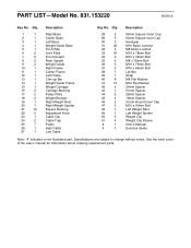
PART LIST-Model No. 831.153220 R0701A Key No. Qty. 28 5 29 5 30 2 31 46 32 4 33 36 34 3 35 4 36 3 37 2 38 1 39 1 40 8 41 12 42 2 43 1 44 2 45 4 46 2 47 2 48 1 49 1 50 2 51 4 # 1 # 1 Description 60mm Square Outer Cap 60mm Square Inner Cap Handgrip M10 Nylon Locknut M8 Nylon Locknut M10 x 78mm Bolt M10 x 45mm Bolt M8 x 72mm Bolt M10 x 75mm Bolt M10 x 66mm Bolt Lat Bar Strap M8 Flat Washer M10 Flat Washer 24mm Spacer 51mm Spacer 28mm Spacer 18mm Spacer 51mm Round Inner Cap M10 x 50mm Bolt Left Weight Rest Left Weight Spotter Weight Clip ...
PART LIST-Model No. 831.153220 R0701A Key No. Qty. 28 5 29 5 30 2 31 46 32 4 33 36 34 3 35 4 36 3 37 2 38 1 39 1 40 8 41 12 42 2 43 1 44 2 45 4 46 2 47 2 48 1 49 1 50 2 51 4 # 1 # 1 Description 60mm Square Outer Cap 60mm Square Inner Cap Handgrip M10 Nylon Locknut M8 Nylon Locknut M10 x 78mm Bolt M10 x 45mm Bolt M8 x 72mm Bolt M10 x 75mm Bolt M10 x 66mm Bolt Lat Bar Strap M8 Flat Washer M10 Flat Washer 24mm Spacer 51mm Spacer 28mm Spacer 18mm Spacer 51mm Round Inner Cap M10 x 50mm Bolt Left Weight Rest Left Weight Spotter Weight Clip ...
English Manual
Page 17
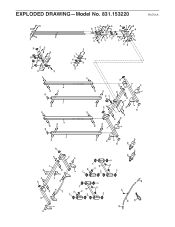
EXPLODED DRAWING-Model No. WEBE24410 10 31 29 31 33 33 11 31 6 41 33 31 29 33 31 13 33 7 21 12 19 21 22 20 21 6 31 21 48 22 21 21 21 22 21 49 30 23 22 21 21 31 31 6 28 38 50 50 39 30 51 51 29 33 33 8 31 33 7 29 33 31 8 25 25 29 31 31 41 14 31 45 47 45 41 36 26 32 40 9 40 35 17 25 31 24 17 31 31 33 33 33 33 1 28 31 31 25 27 33 2 34 6 33 33 33 5 33 6 28 6 31 28 3 31 25 24 34 31 41 42 46 31 26 16 42 41 37 41 15 16 18 43 46 41 37 27 32 31 41 44 40 28 4 31 44 41 35 36 R0701A EXPLODED DRAWING-Model No. 831.153220
EXPLODED DRAWING-Model No. WEBE24410 10 31 29 31 33 33 11 31 6 41 33 31 29 33 31 13 33 7 21 12 19 21 22 20 21 6 31 21 48 22 21 21 21 22 21 49 30 23 22 21 21 31 31 6 28 38 50 50 39 30 51 51 29 33 33 8 31 33 7 29 33 31 8 25 25 29 31 31 41 14 31 45 47 45 41 36 26 32 40 9 40 35 17 25 31 24 17 31 31 33 33 33 33 1 28 31 31 25 27 33 2 34 6 33 33 33 5 33 6 28 6 31 28 3 31 25 24 34 31 41 42 46 31 26 16 42 41 37 41 15 16 18 43 46 41 37 27 32 31 41 44 40 28 4 31 44 41 35 36 R0701A EXPLODED DRAWING-Model No. 831.153220
English Manual
Page 18
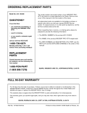
... your nearest SEARS Service Center. All replacement parts are listed on a decal attached to state. When requesting help assembling or operating the WEIDER® PRO XT75 • a part is used commercially or for immediate purchase or special order when you need help or service, or ordering parts,...be replaced, call the following information: • The MODEL NUMBER of the product (831.153220) • The NAME of the product (WEIDER® PRO XT75 weight rack) • The PART NUMBER and DESCRIPTION of the decal. This warranty does not apply when the WEIGHT RACK is missing •...
... your nearest SEARS Service Center. All replacement parts are listed on a decal attached to state. When requesting help assembling or operating the WEIDER® PRO XT75 • a part is used commercially or for immediate purchase or special order when you need help or service, or ordering parts,...be replaced, call the following information: • The MODEL NUMBER of the product (831.153220) • The NAME of the product (WEIDER® PRO XT75 weight rack) • The PART NUMBER and DESCRIPTION of the decal. This warranty does not apply when the WEIGHT RACK is missing •...