
English Manual
Page 2
... DAY WARRANTY 2 IMPORTANT PRECAUTIONS 3 BEFORE YOU BEGIN 4 ASSEMBLY 5 HOW TO USE THE HOME GYM SYSTEM 26 WEIGHT RESISTANCE CHART 28 TROUBLE-SHOOTING AND MAINTENANCE 29 CABLE DIAGRAMS 30 ORDERING REPLACEMENT PARTS Back Cover Note: A PART IDENTIFICATION CHART and a PART LIST/EXPLODED DRAWING are attached to the center of this SEARS WEIGHT...
... DAY WARRANTY 2 IMPORTANT PRECAUTIONS 3 BEFORE YOU BEGIN 4 ASSEMBLY 5 HOW TO USE THE HOME GYM SYSTEM 26 WEIGHT RESISTANCE CHART 28 TROUBLE-SHOOTING AND MAINTENANCE 29 CABLE DIAGRAMS 30 ORDERING REPLACEMENT PARTS Back Cover Note: A PART IDENTIFICATION CHART and a PART LIST/EXPLODED DRAWING are attached to the center of this SEARS WEIGHT...
English Manual
Page 3
... and in any worn parts immediately. When using the home gym system. 3. If you are on the rear seat frame (see page 27). 14. All cables should be replaced every two years. 5. Make sure that the lock pin is clipped in place on a level surface. The home gym system is intended... injury, read the following important precautions before using the leg press station, always be sure that the lock pin is fully inserted and that the cables remain on the adjustment tube (see page 27). 11. Never release the press arm, butterfly arms, leg lever, leg press plate, lat bar, row bar...
... and in any worn parts immediately. When using the home gym system. 3. If you are on the rear seat frame (see page 27). 14. All cables should be replaced every two years. 5. Make sure that the lock pin is clipped in place on a level surface. The home gym system is intended... injury, read the following important precautions before using the leg press station, always be sure that the lock pin is fully inserted and that the cables remain on the adjustment tube (see page 27). 11. Never release the press arm, butterfly arms, leg lever, leg press plate, lat bar, row bar...

English Manual
Page 5
... have read the following tools: A socket set, a set of ratchet wrenches. If a part is divided into four stages: 1) frame assembly, 2) press and butterfly arm assembly, 3) cable and pulley assembly and 4) seat and backrest assembly. Fully tighten the Nylon Locknuts. 1 58 55 58 14 49 57 58 49 13 20 40 49...
... have read the following tools: A socket set, a set of ratchet wrenches. If a part is divided into four stages: 1) frame assembly, 2) press and butterfly arm assembly, 3) cable and pulley assembly and 4) seat and backrest assembly. Fully tighten the Nylon Locknuts. 1 58 55 58 14 49 57 58 49 13 20 40 49...

English Manual
Page 13
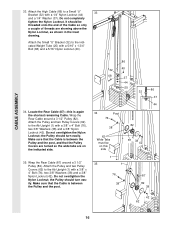
..." 87-148.75" 89-209.5" 88-243" 77 85 5 42 42 82 50 80 4 85 13 Find the Butterfly Cable (85)-this section, fully unwind the five Cables and identify the Cables by comparing the lengths and the ends. Before beginning this is listed after the key number in the groove of... each Cable, in inches, is the 24 shortest Cable. Slide one end of this manual to the CABLE DIAGRAMS on the Leg Press Upright (4) with a 3/8" x 2" Bolt (50) and a 3/8" Nylon Locknut (42). Wrap the...
..." 87-148.75" 89-209.5" 88-243" 77 85 5 42 42 82 50 80 4 85 13 Find the Butterfly Cable (85)-this section, fully unwind the five Cables and identify the Cables by comparing the lengths and the ends. Before beginning this is listed after the key number in the groove of... each Cable, in inches, is the 24 shortest Cable. Slide one end of this manual to the CABLE DIAGRAMS on the Leg Press Upright (4) with a 3/8" x 2" Bolt (50) and a 3/8" Nylon Locknut (42). Wrap the...

English Manual
Page 14
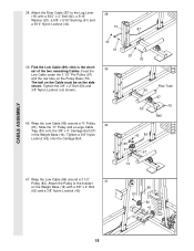
...downward. Leave just enough room for easier part identification. 26. Attach the Pulley and a 27 Cable Trap (80) to the other end of the Pulley. 80 50 42 82 85 4 CABLE ASSEMBLY 28. The Cable Trap must be positioned to pivot. 6 42 14 Insert the Bolt through the bracket on ...) under the indicated 3 1/2" Pulley (82). Be sure that the Cable is between the Cable Trap (80) and the Pulley, and that the Cable Trap is shown removed 28 for the Cable to hold the Cable in the groove of the Butterfly Cable (85) onto a 3/8" x 1" 77 Bolt (77). Note: The Left Arm (6) is ...
...downward. Leave just enough room for easier part identification. 26. Attach the Pulley and a 27 Cable Trap (80) to the other end of the Pulley. 80 50 42 82 85 4 CABLE ASSEMBLY 28. The Cable Trap must be positioned to pivot. 6 42 14 Insert the Bolt through the bracket on ...) under the indicated 3 1/2" Pulley (82). Be sure that the Cable is between the Cable Trap (80) and the Pulley, and that the Cable Trap is shown removed 28 for the Cable to hold the Cable in the groove of the Butterfly Cable (85) onto a 3/8" x 1" 77 Bolt (77). Note: The Left Arm (6) is ...

English Manual
Page 15
...(2). Tighten the 3/8" x 2" Bolt (50) and the 3/8" Nylon Locknut (not shown). 86 50 31 End with the 3/8" Washer (38). 30. It is the shortest remaining Cable. Tighten the 3/8" x 3 1/2" Bolt (66) and the 3/8" Nylon Locknut (42), with two holes should be routed from the direction shown. 42 2 50 82 86 15 Attach... the Pulley and a Cable Trap (80) to hold the Cable in place. 38 42 Post 86 2 82 66 66 38 2 80 82 43 86 31. The end of the Pulley Plates (31) ...
...(2). Tighten the 3/8" x 2" Bolt (50) and the 3/8" Nylon Locknut (not shown). 86 50 31 End with the 3/8" Washer (38). 30. It is the shortest remaining Cable. Tighten the 3/8" x 3 1/2" Bolt (66) and the 3/8" Nylon Locknut (42), with two holes should be routed from the direction shown. 42 2 50 82 86 15 Attach... the Pulley and a Cable Trap (80) to hold the Cable in place. 38 42 Post 86 2 82 66 66 38 2 80 82 43 86 31. The end of the Pulley Plates (31) ...
English Manual
Page 16
...above the Nylon Locknut, as shown in the inset drawing. Do not completely tighten the Nylon Locknut. the Pulley should turn easily. Attach the High Cable (86) to the Ab Upright (1) with a 1/4" Nylon Locknut (44) and a 1/4" Washer (37). Do not overtighten the Nylon Locknut; ...(1) with a 5/16" x 1 3/4" Bolt (68) and a 5/16" Nylon Locknut (40). 34. the Pulley should turn easily. Wrap the Rear Cable around a 3 1/2" Pulley (82). Wrap the Rear Cable (87) around a 3 1/2" Pulley (82). Attach the Pulley and two Pulley Covers (62) to the indicated Weight Tube (25) with a 3/8" x ...
...above the Nylon Locknut, as shown in the inset drawing. Do not completely tighten the Nylon Locknut. the Pulley should turn easily. Attach the High Cable (86) to the Ab Upright (1) with a 1/4" Nylon Locknut (44) and a 1/4" Washer (37). Do not overtighten the Nylon Locknut; ...(1) with a 5/16" x 1 3/4" Bolt (68) and a 5/16" Nylon Locknut (40). 34. the Pulley should turn easily. Wrap the Rear Cable around a 3 1/2" Pulley (82). Wrap the Rear Cable (87) around a 3 1/2" Pulley (82). Attach the Pulley and two Pulley Covers (62) to the indicated Weight Tube (25) with a 3/8" x ...

English Manual
Page 17
... (38) and a 3/8" Jam Nut (43). The Cable must be routed from the direction shown. ing. 36. Route the Press Cable (88) over the indicated 36 3 1/2" Pulley (82) attached to hold the Cable in place. 31 50 82 87 CABLE ASSEMBLY 80 87 37. Wrap the Rear Cable (87) around a 3 1/2" Pulley (82). Be ...sure that the Cable is between the Cable Trap (80) and the Pulley, ...
... (38) and a 3/8" Jam Nut (43). The Cable must be routed from the direction shown. ing. 36. Route the Press Cable (88) over the indicated 36 3 1/2" Pulley (82) attached to hold the Cable in place. 31 50 82 87 CABLE ASSEMBLY 80 87 37. Wrap the Rear Cable (87) around a 3 1/2" Pulley (82). Be ...sure that the Cable is between the Cable Trap (80) and the Pulley, ...
English Manual
Page 18
...) to the bracket 41 on the Pulley Base (79). Feed the Low Cable under the 3 1/2" Pro Pulley (97) and the row tube on the Weight Base (14) with a 5/16" x 3" Bolt (92), a 5/16" Washer (20), a 5/8" x 9/16" Bushing (61) and a 5/16" Nylon Locknut (... (15) with a 3/8" x 2" Bolt (50) and a 3/8" Nylon Locknut (42). 89 50 82 42 14 18 Wrap the Low Cable (89) around a 3 1/2" Pulley (82). Wrap the Low Cable (89) around a "V" Pulley (81). The ball on the Cable must be on the side shown. Tighten a 3/8" Nylon Locknut (42) onto the Carriage Bolt. 40 61 39 20...
...) to the bracket 41 on the Pulley Base (79). Feed the Low Cable under the 3 1/2" Pro Pulley (97) and the row tube on the Weight Base (14) with a 5/16" x 3" Bolt (92), a 5/16" Washer (20), a 5/8" x 9/16" Bushing (61) and a 5/16" Nylon Locknut (... (15) with a 3/8" x 2" Bolt (50) and a 3/8" Nylon Locknut (42). 89 50 82 42 14 18 Wrap the Low Cable (89) around a 3 1/2" Pulley (82). Wrap the Low Cable (89) around a "V" Pulley (81). The ball on the Cable must be on the side shown. Tighten a 3/8" Nylon Locknut (42) onto the Carriage Bolt. 40 61 39 20...

English Manual
Page 19
... from the direction shown. 42 2 50 82 89 19 Attach a 3 1/2" Pulley (82) and a Cable Trap (80) to the indicated bracket on the Top Frame (2) with a 3/8" x 2" Bolt (50) and a 3/8" Nylon Locknut (42). Wrap the Low Cable (89) around a 3 1/2" 42 Pulley (82). Attach the Pulley to the upper hole 43 in the... groove of 42 50 the Pulley and that the Cable Trap is inside the 89 Large "U" Bracket. The Cable must be routed from the direction shown. 2 42 50 82 89 CABLE ASSEMBLY 43. Note: This may come pre-assembled. 80 82 Route the Low...
... from the direction shown. 42 2 50 82 89 19 Attach a 3 1/2" Pulley (82) and a Cable Trap (80) to the indicated bracket on the Top Frame (2) with a 3/8" x 2" Bolt (50) and a 3/8" Nylon Locknut (42). Wrap the Low Cable (89) around a 3 1/2" 42 Pulley (82). Attach the Pulley to the upper hole 43 in the... groove of 42 50 the Pulley and that the Cable Trap is inside the 89 Large "U" Bracket. The Cable must be routed from the direction shown. 2 42 50 82 89 CABLE ASSEMBLY 43. Note: This may come pre-assembled. 80 82 Route the Low...

English Manual
Page 20
... (32) with a 5/16" x 1 3/4" Bolt (68) and a 5/16" Nylon Locknut (40). 46. Find the Press Cable (88). It should be threaded onto the end of the Cable so only a couple of threads are showing above the Nylon Locknut, as shown in place. Note: The 3 1/2" Pulley (82) in...32 cated Weight Tube (25) with a 1/4" Nylon Locknut (44) and a 1/4" Washer (37). Route the Press Cable (88) around the 3 1/2" Pulley (82) attached to hold the Cable in the inset drawing. Do not completely tighten the Nylon Locknut. Do not completely tighten the Nylon Locknut. Attach the Small...
... (32) with a 5/16" x 1 3/4" Bolt (68) and a 5/16" Nylon Locknut (40). 46. Find the Press Cable (88). It should be threaded onto the end of the Cable so only a couple of threads are showing above the Nylon Locknut, as shown in place. Note: The 3 1/2" Pulley (82) in...32 cated Weight Tube (25) with a 1/4" Nylon Locknut (44) and a 1/4" Washer (37). Route the Press Cable (88) around the 3 1/2" Pulley (82) attached to hold the Cable in the inset drawing. Do not completely tighten the Nylon Locknut. Do not completely tighten the Nylon Locknut. Attach the Small...

English Manual
Page 21
... (80) to the Pulley 49 Plates (31). It is positioned to hold the Cable 88 in place. 51. ing. Wrap the Press Cable (88) around a 3 1/2" Pulley (82). Be sure that the Cable Trap (80) is turned as shown to hold the Cable in the Press Frame (12) with a 3/8" x 3 1/2" Bolt (66),...the Leg Press Upright (4) with a 3/8" x 3 1/2" Bolt (66), a 3/8" Washer (38) and a 3/8" Nylon Locknut (42). Attach the Pulley and a Cable 51 Trap (80) to hold the Cable in this step is pre-assembled. Tighten the 3/8" x 2" Bolt (50) and the 3/8" Nylon Locknut (42). 48 50 88 82 80 42 13...
... (80) to the Pulley 49 Plates (31). It is positioned to hold the Cable 88 in place. 51. ing. Wrap the Press Cable (88) around a 3 1/2" Pulley (82). Be sure that the Cable Trap (80) is turned as shown to hold the Cable in the Press Frame (12) with a 3/8" x 3 1/2" Bolt (66),...the Leg Press Upright (4) with a 3/8" x 3 1/2" Bolt (66), a 3/8" Washer (38) and a 3/8" Nylon Locknut (42). Attach the Pulley and a Cable 51 Trap (80) to hold the Cable in this step is pre-assembled. Tighten the 3/8" x 2" Bolt (50) and the 3/8" Nylon Locknut (42). 48 50 88 82 80 42 13...

English Manual
Page 22
Attach the "V" Pulley to the upper bracket on the Press Frame. 42 80 12 66 38 82 Crossbar 54. Be sure that the Cable is turned to the lower 54 bracket on the Leg Press Upright (4) with a 3/8" x 2" Bolt (50) and a 3/8" Nylon Jam Nut (43). 4 81 88 43 50 55.... the Press Frame (12) with a 3/8" x 2" Bolt (50) and a 3/8" Nylon Jam Nut (43). 50 81 4 CABLE ASSEMBLY 88 43 53. Attach the Pulley and a Cable Trap (80) to the indicated hole in place and that the Cable Trap is between the Pulley and the cross- Slide another 3 1/2" Pulley (82) with the 3/8" x 4 1/2" Bolt (74)....
Attach the "V" Pulley to the upper bracket on the Press Frame. 42 80 12 66 38 82 Crossbar 54. Be sure that the Cable is turned to the lower 54 bracket on the Leg Press Upright (4) with a 3/8" x 2" Bolt (50) and a 3/8" Nylon Jam Nut (43). 4 81 88 43 50 55.... the Press Frame (12) with a 3/8" x 2" Bolt (50) and a 3/8" Nylon Jam Nut (43). 50 81 4 CABLE ASSEMBLY 88 43 53. Attach the Pulley and a Cable Trap (80) to the indicated hole in place and that the Cable Trap is between the Pulley and the cross- Slide another 3 1/2" Pulley (82) with the 3/8" x 4 1/2" Bolt (74)....

English Manual
Page 23
... (55). Locate and open the parts bag labeled "SEAT ASSEMBLY." Note: The 3 1/2" Pulley (82) used in this step was attached in place and that the Cable is turned to the bracket on the Front Seat Frame (8) with two 1/4" x 2 1/2" Machine Screws (64) and two 1/4" Washers (37). 55 59 88 8 91 20 ...4 64 19 37 SEAT ASSEMBLY 23 Slide the end of the Press Cable (88) onto the Bolt. Leave enough room between the two Jam Nuts for easier part identification. Insert the Bolt into the Front Seat Frame (8). Wrap...
... (55). Locate and open the parts bag labeled "SEAT ASSEMBLY." Note: The 3 1/2" Pulley (82) used in this step was attached in place and that the Cable is turned to the bracket on the Front Seat Frame (8) with two 1/4" x 2 1/2" Machine Screws (64) and two 1/4" Washers (37). 55 59 88 8 91 20 ...4 64 19 37 SEAT ASSEMBLY 23 Slide the end of the Press Cable (88) onto the Bolt. Leave enough room between the two Jam Nuts for easier part identification. Insert the Bolt into the Front Seat Frame (8). Wrap...

English Manual
Page 25
... and 31 of the remaining parts will need to remove the slack by tightening the cables. See TROUBLE-SHOOTING AND MAINTENANCE on page 26 of the cables does not move smoothly over the pulleys. IMPORTANT: If the cables are not properly installed, they may be damaged when heavy weight is any slack in... LEG EXTENSION/CURL ARM PRESS LEG PRESS SERIAL NUMBER DECAL LOW PULLEY/ROW 65. Make sure that the cables move smoothly, find and correct the problem. Before using the home gym system, pull each cable a few times to the home gym system in the locations shown in HOW TO USE THE HOME...
... and 31 of the remaining parts will need to remove the slack by tightening the cables. See TROUBLE-SHOOTING AND MAINTENANCE on page 26 of the cables does not move smoothly over the pulleys. IMPORTANT: If the cables are not properly installed, they may be damaged when heavy weight is any slack in... LEG EXTENSION/CURL ARM PRESS LEG PRESS SERIAL NUMBER DECAL LOW PULLEY/ROW 65. Make sure that the cables move smoothly, find and correct the problem. Before using the home gym system, pull each cable a few times to the home gym system in the locations shown in HOW TO USE THE HOME...
English Manual
Page 26
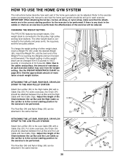
...the Lat Bar (36) to the High Cable (86) with two Cable Clips. HOW TO USE THE HOME GYM SYSTEM The instructions below describe how each part of the home gym system can be changed from the weight setting. CHANGING THE WEIGHT SETTING The PRO 9735 features two weight stacks. Refer to the ...exercise poster accompanying this manual to see how the home gym system should be attached between the Lat Bar and the Low Cable so the Lat Bar is in the correct starting position for...
...the Lat Bar (36) to the High Cable (86) with two Cable Clips. HOW TO USE THE HOME GYM SYSTEM The instructions below describe how each part of the home gym system can be changed from the weight setting. CHANGING THE WEIGHT SETTING The PRO 9735 features two weight stacks. Refer to the ...exercise poster accompanying this manual to see how the home gym system should be attached between the Lat Bar and the Low Cable so the Lat Bar is in the correct starting position for...

English Manual
Page 27
... Lever Frame. Be sure that the hook on the Lock Pin is at the highest position, you use the upper foam pads to the Rear Cable (87) at the desired height, align the holes in the Adjustment Tube (10). Reinsert the Lock Pin (73) through both the rear seat frame and... of the Leg Lever (15), remove the Large Lock Pin (96) from the Adjustment Tube (10). Align the holes in the Leg Press Arm (9) with a Cable Clip (33). 33 35 ADJUSTING THE LEG LEVER To change the height of holes in the Rear Seat Frame and Leg Lever Frame and re...
... Lever Frame. Be sure that the hook on the Lock Pin is at the highest position, you use the upper foam pads to the Rear Cable (87) at the desired height, align the holes in the Adjustment Tube (10). Reinsert the Lock Pin (73) through both the rear seat frame and... of the Leg Lever (15), remove the Large Lock Pin (96) from the Adjustment Tube (10). Align the holes in the Leg Press Arm (9) with a Cable Clip (33). 33 35 ADJUSTING THE LEG LEVER To change the height of holes in the Rear Seat Frame and Leg Lever Frame and re...

English Manual
Page 28
... chart shows the approximate weight resistance at each weight station may vary due to differences in individual weight plates, as well as friction between the cables, pulleys and weight guides. 28
... chart shows the approximate weight resistance at each weight station may vary due to differences in individual weight plates, as well as friction between the cables, pulleys and weight guides. 28
English Manual
Page 29
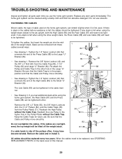
...Slack can be tightened. Remove the 3/8" x 2" Bolts (50), the 3/8" Nylon Locknuts (42), the 3 1/2" Pulleys (82), and the Cable Traps (80) from the Cable Trap (80), 3 1/2" Pulley (82) and Large "U" Bracket (84). Replace any slack is felt when using the home gym system, the... Nylon Locknut (42) and the 3/8" x 2" Bolt (50) from the Pulley Plates (31). All cables should be tightened. Reattach the High Pulley without the Cable Trap. When the cables need to be tightened. TROUBLE-SHOOTING AND MAINTENANCE Inspect and tighten all parts each time you feel additional slack...
...Slack can be tightened. Remove the 3/8" x 2" Bolts (50), the 3/8" Nylon Locknuts (42), the 3 1/2" Pulleys (82), and the Cable Traps (80) from the Cable Trap (80), 3 1/2" Pulley (82) and Large "U" Bracket (84). Replace any slack is felt when using the home gym system, the... Nylon Locknut (42) and the 3/8" x 2" Bolt (50) from the Pulley Plates (31). All cables should be tightened. Reattach the High Pulley without the Cable Trap. When the cables need to be tightened. TROUBLE-SHOOTING AND MAINTENANCE Inspect and tighten all parts each time you feel additional slack...
English Manual
Page 30
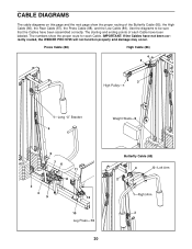
... 2 3 9 12 10 Leg Press-13 30 Butterfly Cable (85) 4 5-Left Arm 2 1-Right Arm 3 CABLE DIAGRAMS The cable diagrams on this page and the next page show the proper route for each Cable have not been correctly routed, the WEIDER PRO 9735 will not function properly and damage may occur. Use the... diagrams to be sure that the Cables have been assembled correctly...
... 2 3 9 12 10 Leg Press-13 30 Butterfly Cable (85) 4 5-Left Arm 2 1-Right Arm 3 CABLE DIAGRAMS The cable diagrams on this page and the next page show the proper route for each Cable have not been correctly routed, the WEIDER PRO 9735 will not function properly and damage may occur. Use the... diagrams to be sure that the Cables have been assembled correctly...


